Advertisement
SERVICE MANUAL
SPECIFICATIONS
TV standard
Color
system
Channel
coverage
Radio
frequency
range
Antenna
Picture size
Speaker
EXT ANT (TV)
VIDEO
IN
output
Power requirement
Power
consumption
Dimensions
M a s s
Supplied
accessory
Design and specifications are subject to change
without notice.
American TV standard
N T S C
VHF
channel
2-13
UHF
channel
14-69
VHF/UHF/FM:
telescopic
antenna
antenna
picture measured
diagonally
80mm (3 f/4 inches) dia.
minijack,
impedance
75 ohms (for TV)
jack,
1 Vp-p. 75 ohms,
unbalanced,
sync
negative
AUDIO:phono
jack,
-7.5 dBs, input impedance
more than 47 kilohms.
E A R P H O N E : e a r p h o n e
jack, impedance 8-300 ohms
DC, See "Power
sources". (page 4)
20W (135V. 1.48A)
AC
adaptor
use
(w/h/d)
(6
projecting parts
(5 lb 15 oz)
AC power adaptor (ACE55) (1)
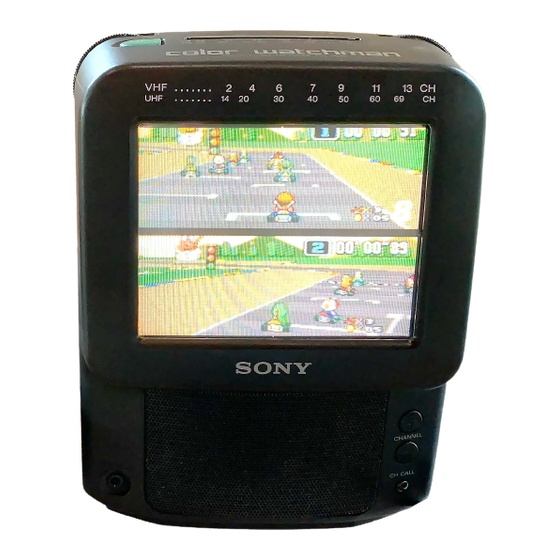
FEATURES
. Equipped with a 5-inch
CRT Color TV.
s o u n d .
monitor for video equipment.
. The voltage synthesizer tuning system allows
for easy tuning.
COLOR TV-AM/FM TUNER
US Model
Advertisement
Table of Contents

Related Manuals for Sony FDT-5BX5


Summary of Contents for Sony FDT-5BX5
- Page 1 SERVICE MANUAL US Model FEATURES SPECIFICATIONS . Equipped with a 5-inch CRT Color TV. American TV standard TV standard Color system N T S C channel 2-13 Channel coverage s o u n d . channel 14-69 Radio frequency monitor for video equipment. range .
-
Page 2: Table Of Contents
REMOVALOFANODECAP Ground using the slotted screwdriver properly when remov- ing the anode cap to prevent any electrical shocks from @When one Li d e of the rubber cap is @Turn up one side of the rubber cap in the @Using a thumb pull up the rubber cap separated from the anode button, the firmly in the direction indicated by the direction indicated by the arrow 0. - Page 3 SAFETY CHECK-OUT LEAKAGE TEST After correcting the original service problem, perform the following safety checks before releasing The AC leakage from any exposed metal part to the set to the customer: earth ground and from all exposed metal parts to any Check the area of your repair for unsoldered or exposed metal part having a return to chassis, must poorly-soldered connections.
-
Page 4: General
SECTION 1 GENERAL This section is extracted from instruction manual. VHF antenna UHF antenna de VHF de UHF Video camera recorder antenna cab,* antenna cable ( n o t s u p p l i e d ) Cable de antena to vidwlaudio a Las tamaS de salida... - Page 5 CONTR COLOR a EARPHONE H U E Listening to the Radio H...
-
Page 6: Disassembly
SECTION 2 DISASSEMBLY Note : Follow the disassembly procedure in the numerical order given. 2-1. REAR CABINET... -
Page 7: Dial Assy
2-3. DIAL ASSY (When removing, take care of catch by the band knobs.) @tapping screw washer he a d... -
Page 8: Dial Pointer Setting
2-5. DIAL POINTER SETTING the direction of arrow. -
Page 9: Safety Related Adjustments
SECTION 3 SAFETY RELATED ADJUSTMENTS CONFIRMATION FOR HOLD-DOWN CIRCUIT When replacing the components (marked with 0 on the When replacing the components (marked with a on the schematic diagram), perform the adjustment as follows : schematic diagram), perform the following confirmation. TP502 (FBT), L505 (DY : Supplied with Picture tube.), C555, C571, C556, L503, IC301, IC503, D503, D507, R562, R563, R573, Supply 13.5f0.5V DC to the DC IN jack. -
Page 10: Diagrams
SECTION 4 DIAGRAMS 4-1. SEMICONDUCTOR LEAD LAYOUTS 8 7 6 5 c a t h o d e a n o d e ( T O P V I E W ) ( M A R K I N G S I D E V I E W ) L A 7 8 3 0... -
Page 11: Exploded Views
SECTION 5 EXPLODED VIEWS NOTE: -XX and -X mean standardized parts, so Hardware (# mark) list is given The mechanical parts with no reference they may have some difference from the in the la& of this parts ii&. number in the exploded views are not original one. -
Page 12: Front Cabinet Section
FRONT CABINET SECTION 5-2. I II Remark Ref. No. Part No. Description Remark Ref. No. Part No. Description * 5 9 4-041-785-01 BRACKET E, SP ( BLAC A-3016-486-A R BOARD, COMPLETE 3-714-118-01 SCREW (1.7X4) 4-041-771-01 CABINET (FRONT) (BLACK) * 6 2 4-041-787-01 DRUM, TUNING CAPACITOR FILTER * 6 4... -
Page 13: Electrical Parts List
SECTION 6 ELECTRICAL PARTS LIST N O T E : The components identified by Due to standardization, replacements in Items marked “*‘I are not stocked since mark A or dotted line with mark the parts list may be different from the they are seldom required for routine service. - Page 14 Remark Ref. No. Part No. Description Remark Ref. No. Part No. Description C325 l-163-031-11 CERAMIC CHIP 0. OluF < DELAY LINE > C326 1-163-245-11 CERAMIC CHIP 56PF C327 l-163-038-00 CERAMIC CHIP l-406-920-11 DELAY LINE 0. 1uF 2 5 V C328 l-130-495-00 MYLAR 0.
- Page 15 Ref. No. Part No. Description Description Remark Remark Ref. No. Part No. TRANSISTOR DTC124XK R143 l-216-022-00 METAL CHIP R150 l-216-073-00 METAL CHIP Q315 8-729-230-49 TRANSISTOR 2SC2712-YG R151 l-216-073-00 METAL CHIP Q350 a-729-230-49 TRANSISTOR 2SC2712-YG l-216-073-00 METAL CHIP Q351 a-729-230-49 TRANSISTOR 2SC2712-YG l-216-073-00 METAL CHIP l-216-081-00 METAL CHIP 22K 5%...
- Page 16 Description Remark Ref. No. Part No. Description Remark Ref. No. Part No. R304 l-216-049-00 METAL CHIP R370 l-216-059-00 METAL CHIP l-216-083-00 METAL CHIP R371 l-216-069-00 METAL CHIP R305 27K 5% l-216-077-00 METAL CHIP 15K 5% l-216-033-00 METAL CHIP 2 2 0 R380 R307 l-216-033-00 METAL CHIP...
- Page 17 Remark Remark Ref. No. Part No. Description Ref. No. Part No. Description A-3016-483-A D BOARD, COMPLETE (INCLUDING C BOARD) < VIBRATOR > Xl01 1-567-818-21 VIBRATOR, CERAMIC (3.58MHz) 1-533-233-11 HOLDER, FUSE X301 l-567-505-11 VIBRATOR, CRYSTAL (3.58MHz) X302 l-577-706-11 VIBRATOR, CERAMIC (503.5kHz) <...
- Page 18 Ref. No. Part No. Description Remark Ref. No. Part No. Description Remark * CN504 1-764-265-11 PIN, CONNECTOR (PC BOARD) 4P < RESISTOR > * CN506 l-506-947-11 PIN, CONNECTOR 6P * CN603 l-506-947-11 PIN, CONNECTOR 6P 1-249-424-11 CARBON 1-249-421-11 CARBON 4 7 0 <...
- Page 19 Ref. No. Part No. Description Remark Ref. No. Part No. Description Remark < VARIABLE RESISTOR > < COIL > l-238-600-11 RES, ADJ, CARBON 10K l-238-601-11 RES, ADJ, CARBON 22K l-410-396-41 INDUCTOR l-238-601-11 RES, ADJ, CARBON 22K l-238-600-11 RES, ADJ, CARBON 10K 8-759-100-75 IC UPC1394C E-759-054-08 IC MC34063AM T501 1-423-862-11 TRANSFORMER, HORIZONTAL DRIVE...
- Page 20 Remark Ref. No. Part No. Description Remark Ref. No. Part No. Description < FILTER > < R E L A Y > 1-515-738-11 RELAY FL12 1-236-711-21 FILTER, BAND PASS < IC > < SWITCH > IC12 B-752-061-79 IC CX20111-T6 < TRANSFORMER > <...
- Page 21 FDT-5 BX5 Ref. No. Part No. Description Remark ACCESSORIES & PACKING MATERIALS 1-467-372-11 ADAPTOR, (AC-E55) 3-757-566-21 MANUAL, INSTRUCTION (ENGLISR, SPANISH) 4-041-757-01 INDIVIDUAL CARTON HARDWARE LIST 7-685-661-79 HEAD, WASHER, TAPPING SCREW 7-626-323-61 SPRING PIN 4X20 7-682-549-04 SCREW +B 3X10 7-685-648-79 SCREW +BVTP 3X12 TYPE2 N-S 7-685-903-21 SCREW +PTPWH The components identified by mark A or dotted line with mark.
Need help?
Do you have a question about the FDT-5BX5 and is the answer not in the manual?
Questions and answers