Pioneer DJM-909 Service Manual
Hide thumbs
Also See for DJM-909:
- Operating instructions manual (28 pages) ,
- Operating instructions manual (140 pages) ,
- Training manual (50 pages)
Table of Contents
Advertisement
Quick Links
DJ MIXER
DJM-909
THIS MANUAL IS APPLICABLE TO THE FOLLOWING MODEL(S) AND TYPE(S).
Model
Type
DJM-909
KUCXJ
DJM-909
WYXJ
DJM-909
TLTXJ
For details, refer to "Important symbols for good services" .
PIONEER CORPORATION
PIONEER ELECTRONICS (USA) INC. P.O. Box 1760, Long Beach, CA 90801-1760, U.S.A.
PIONEER EUROPE NV Haven 1087, Keetberglaan 1, 9120 Melsele, Belgium
PIONEER ELECTRONICS ASIACENTRE PTE. LTD. 253 Alexandra Road, #04-01, Singapore 159936
PIONEER CORPORATION 2003
Power Requirement
AC120V
AC220 - 240V
AC110 - 240V
4-1, Meguro 1-chome, Meguro-ku, Tokyo 153-8654, Japan
PHONO 1
PHONO 2
MIC
/LINE 1
CD 1
CH-1
/LINE 2
CD 2
BANK 1
BANK 1
MIC LEVEL
MASTER LEVEL
TRIM
TRIM
BANK 2
BANK 2
–
0
–
0
HI
BOOTH/SESSION OUT
BANK 3
BANK 3
–
+9
–
+9
HI
HI
-12
+12
FX ADJ.
FX ADJ.
–
0
LOW
PHONES
-26
+6
-26
+6
FADER
FADER
MID
CURVE
CURVE
MID
+12
–
0
-12
BANK
BANK
EDIT
EDIT
SELECT
MIC SEND
MASTER
PROFESSIONAL 2CHANNEL MIXER
TIME/SELECT
DJM-909
TIME/SELECT
-26
+6
-26
+6
EFFECT
LOW
LOW
CUE
EFFECT
EFFECT
SESSION IN
LOCK ON
CH-1
CH-2
MIX/DEPTH
OFF
MIX/DEPTH
-26
+6
-26
+6
ON
–
0
EQ
EQ
CH-1 SEND
CH-2 SEND
OFF
OFF
MIN
MAX
MIN
MAX
TAP
TAP
ON
ON
TRANSFORM
TRANSFORM
FADER START
FADER START
MASTER LEVEL
REVERSE
REVERSE
L
R
CH-1
14
14
CH-2
9
9
10
5
5
10
9
3
3
9
8
1
1
8
7
7
0
0
6
6
–
1
–
1
5
5
–
3
–
3
4
4
CH-1 FADER START
CH-2 FADER START
–
6
–
6
3
3
2
–
9
–
9
2
1
–
15
–
15
1
0
0
–
22
–
22
dB
dB
CH-1
CH-2
REVERSE
C.F.1 FADER START
C.F.2 FADER START
1
2
FEELING
ADJ.
PHONES
FOOT SW
POWER
DJM-909
ORDER NO.
RRV2871
Remarks
T-ZZY DEC. 2003 printed in Japan
Advertisement
Table of Contents

Related Manuals for Pioneer DJM-909


Summary of Contents for Pioneer DJM-909
- Page 1 PIONEER CORPORATION 4-1, Meguro 1-chome, Meguro-ku, Tokyo 153-8654, Japan PIONEER ELECTRONICS (USA) INC. P.O. Box 1760, Long Beach, CA 90801-1760, U.S.A. PIONEER EUROPE NV Haven 1087, Keetberglaan 1, 9120 Melsele, Belgium PIONEER ELECTRONICS ASIACENTRE PTE. LTD. 253 Alexandra Road, #04-01, Singapore 159936 PIONEER CORPORATION 2003 T-ZZY DEC.
-
Page 2: Safety Information
Leakage The use of a substitute replacement component which does 0.5mA current Device not have the same safety characteristics as the PIONEER tester under recommended replacement one, shown in the parts list in test this Service Manual, may create shock, fire, or other hazards. -
Page 3: Table Of Contents
3.9 DSP ASSY (1/2) ............................34 3.10 DSP ASSY (2/2) .............................36 3.11 C1EQ ASSY (1/2) ...........................38 3.12 C1EQ ASSY (2/2) ...........................40 3.13 C2EQ ASSY ............................42 3.14 C1BF ASSY ............................44 3.15 C2BF ASSY ............................46 3.16 MICB ASSY ............................48 3.17 HPBO ASSY ............................50 DJM-909... - Page 4 7.1.3 POWER ON SEQUENCE........................ 135 7.1.4 Table of the roles of the microcomputers ..................136 7.1.5 DISASSEMBLY..........................138 7.1.6 CONFIGURATION OF THE PC BOARD ..................144 7.2 PARTS..............................145 7.2.1 IC INFORMATION ........................... 145 8. PANEL FACILITIES AND SPECIFICATIONS ....................150 DJM-909...
-
Page 5: Specifications
LOW ..............+12 dB to –12 dB Accessories ÷ Hexagonal Allen driver ............. 1 ÷ These operating instructions............. 1 For improvement purposes, specifications and design may be subject to modification without notice. Accessories ¶ Operating instructions....x1 ¶ Hexagonal Allen driver..x1 (DEX1018) ¶ Warranty........x1 DJM-909... -
Page 6: Exploded Views And Parts List
Screws adjacent to mark on product are used for disassembly. For the applying amount of lubricants or glue, follow the instructions in this manual. (In the case of no amount instructions, apply as you think it appropriate.) 2.1 PACKING FRONT DJM-909... - Page 7 NSP 10 Label VRW1629 (0.03 x 230 x 340) Pad (A) DHA1586 (2) CONTRAST TABLE DJM-909/ KUCXJ, DJM-909/ WYXJ and DJM-909/ TLTXJ are constructed the same except for the following : DJM-909 DJM-909 DJM-909 Mark No. Symbol and Description KUCXJ...
-
Page 8: Exterior Section
2.2 EXTERIOR SECTION Refer to "2.4 CONTROL PANEL (UPPER) SECTION". Refer to "2.3 CONTROL PANEL (LOWER) SECTION". NON-CONTACT SIDE CONTACT SIDE Refer to "2.5 FRONT PANEL SECTION". DJM-909... - Page 9 DDD1241 Connector Assy (8P) DKP3660 Connector Assy PF08EE-D15 Connector Assy DKP3659 (2) CONTRAST TABLE DJM-909/ KUCXJ, DJM-909/ WYXJ and DJM-909/ TLTXJ are constructed the same except for the following : DJM-909 DJM-909 DJM-909 Mark No. Symbol and Description KUCXJ WYXJ TLTXJ >...
-
Page 10: Control Panel (Lower) Section
2.3 CONTROL PANEL (LOWER) SECTION NON-CONTACT SIDE CONTACT SIDE DSP ASSY (EXTERIOR SECTION: No.24) DSP ASSY (EXTERIOR SECTION: No.10) DJM-909... - Page 11 DXB1787 Guide Shaft DLA1966 Screw BPZ30P080FMC MG Plate Assy DXA1968 (2) CONTRAST TABLE DJM-909/ KUCXJ, DJM-909/ WYXJ and DJM-909/ TLTXJ are constructed the same except for the following : DJM-909 DJM-909 DJM-909 Mark No. Symbol and Description KUCXJ WYXJ TLTXJ...
-
Page 12: Control Panel (Upper) Section
2.4 CONTROL PANEL (UPPER) SECTION NON-CONTACT SIDE Types of the rotary Knobs (by color) No.6 No.7 No.8 CONTACT SIDE Gray Gray (No indicating line) No.9 No.10 Gray Wide Wide CIBF ASSY C2BF ASSY (EXTERIOR SECTION: No.12) (EXTERIOR SECTION: No.41) DJM-909... - Page 13 • • • • • Cue Fader Bracket DNF1690 Earth Plate DNH2577 (2) CONTRAST TABLE DJM-909/ KUCXJ, DJM-909/ WYXJ and DJM-909/ TLTXJ are constructed the same except for the following : DJM-909 DJM-909 DJM-909 Mark No. Symbol and Description KUCXJ...
-
Page 14: Front Panel Section
2.5 FRONT PANEL SECTION DSP ASSY (EXTERIOR SECTION: No.30) MAIN ASSY (EXTERIOR SECTION: No.39) NON-CONTACT SIDE CONTACT SIDE DJM-909... - Page 15 AMZ26P040FMC Slide SW Packing (A) DEC2589 Screw PMA30P060FMC Washer DBE1010 (2) CONTRAST TABLE DJM-909/ KUCXJ, DJM-909/ WYXJ and DJM-909/ TLTXJ are constructed the same except for the following : DJM-909 DJM-909 DJM-909 Mark No. Symbol and Description KUCXJ WYXJ TLTXJ...
-
Page 16: Block Diagram And Schematic Diagram
(1/2) Fader CUE_R_OUT TRIM IC1750 VR1754 VR1753 VR1752 IC1751 NJM4558MD (1/2) NJM5532MD (2/2) Buffer IC1748 IC1754 NJM4558MD NJM4580MD (1/2) (1/2) (1/2) (2/2) CUE_L1 CUE_R1 IC1755 IC1753 IC1752 CUE_L2 NJM4580MD NJM4580MD NJM4580MD CN1754 CUE_R2 C2EQ ASSY 3 Band Equalizer (7P) DJM-909... - Page 17 TC9215AF (1/2) Level BOOTH_OUT_R (1/2) IC1454 CN125 CN582 NJM2068M VR1453 RY1451 (6P) (6P) VR1451 JA581 HP_L Master (2/2) (1/2) Level PHONES HP_R IC1451 HP Level CN1452 CN119 NJM5532MD (20P) (20P) IC1455 TC9215AF FSSW ASSY HP Monitor SW HPBO ASSY DJM-909...
-
Page 18: Dsp/ Lcd Block Diagram
3.1.2 DSP/ LCD BLOCK DIAGRAM 9,10,11,12 SDT0,LRCK,MCLK,SCLK AIN L 3,5,10,12 1,7,8,14 V1-V4 DT0-DT15 AD0-AD19 SYSCLK VCA1-CONT VCA2-CONT EXTAL LCD ASSY 9,10,11,12 AIN L SDT0,LRCK,MCLK,SCLK DJM-909... - Page 19 DATA VOUT L DATA VOUT L DSP ASSY A0-A11 D0-14 TXD,RXD,SCK FPWM1 FPWM2 DATA VOUT L DATA VOUT L DJM-909...
-
Page 20: Overall Connection Diagram
CONNECTOR ASSY DKP3660 1/2 - XLR ASSY (DWX2322) 35P FFC DDD1241 1/6 - MAIN ASSY (DWX2337) 27P FFC DDD1242 15P FFC CH1 EQ Low ADJ. DDD1243 CH1 EQ Mid ADJ. CH1 EQ Hi ADJ. MICB ASSY (DWX2318) SDRT ASSY (DWX2321) DJM-909... - Page 21 ÷ The > mark found on some component parts indicates the importance of the safety factor POWER CORD KUCXJ : VDG1075 of the part. Therefore, when replacing, be sure to use parts of identical designation. WYXJ : VDG1077 TLTXJ : VDG1077 ÷ : The power supply is shown with the marked box. DJM-909...
-
Page 22: Main Assy (1/6)
3.3 MAIN ASSY (1/6) (CH1) (CH1) (CH1) (CH2) (CH2) (CH1_D) (CH2_D) (CH1_D) (MIC) EFFECT MIX ON/OFF (RET) (SES) (CH1_D) (CH1) (CH2) (CH1_D) (CH2_D) EFFECT MIX (CH2_D) (CH2_D) (MIC) ON/OFF DJM-909... - Page 23 : Channel_2 DSP Signal Route (MIC) : Microphone Signal Route (SEND) : Send Signal Route (RET) : Return Signal Route (SES) : Session Signal Route CN124 2/6, 4/6-6/6 • SEND MIX BLOCK (CH1) (CH1) (CH2) (CH2) (CH1_D) (CH1_D) (CH2_D) (CH2_D) (MIC) (MIC) (SEND) DJM-909...
-
Page 24: Main Assy (2/6)
3.4 MAIN ASSY (2/6) MAIN ASSY (DWX2337) (MA_2) 5/6, 6/6 DJM-909... - Page 25 (MA_2) : MASTER_2 Signal Route (BOOTH) : Booth Signal Route (MA_2) (MA_2) (MA_2) (MA_2) (BOOTH) (BOOTH) UPPER LOWER DJM-909...
-
Page 26: Main Assy (3/6)
3.5 MAIN ASSY (3/6) MAIN ASSY (DWX2337) CN1251 (CH1) (SES) (CH1) (CH1) (CH1_D) (MIC_TH) (CH1) CN1252 (CH2) (CH1) (CH2_D) CN1351 (CH2) (CH2) DJM-909... - Page 27 : Channel_1 DSP Signal Route (CH2_D) : Channel_2 DSP Signal Route (MIC_TH) : Microphone Through Signal Route (SES) : Session Signal Route (CH1) (CH1) (CH1) (CH1_D) (CH1_D) (CH1_D) 5/6, 6/6 5/6, 6/6 (CH2) (CH2) (CH2) (CH2) (CH2_D) (CH2_D) (CH2_D) 5/6, 6/6 5/6, 6/6 DJM-909...
-
Page 28: Main Assy (4/6)
3.6 MAIN ASSY (4/6) MAIN ASSY (DWX2337) (MIC_TH) (MIC_TH) (MIC_TH) (MIC) (MIC) (MIC) MIC MIX ON/OFF (MIC) (MIC) (MIC) (MIC) (RET) (RET) (SEND) (SEND) DJM-909... - Page 29 (MIC) : Microphone Signal Route (MIC_TH) : Microphone Through Signal Route (SEND) : Send Signal Route (RET) : Return Signal Route CONTROL (MIC_TH) (MIC) (MIC) (MIC) DJM-909...
-
Page 30: Main Assy (5/6)
3.7 MAIN ASSY (5/6) MAIN ASSY (DWX2337) 3/6, 6/6 (CH2_D) (CH2_D) (CH2_D) (CH2_D) 3/6, 6/6 (CH2_D) (CH2_D) (CH2_D) (CH1_D) (CH1_D) (CH1_D) (CH1_D) (CH1_D) 2/6, 6/6 (CH1_D) (CH1_D) 2/6, 6/6 3/6, 6/6 3/6, 6/6 DJM-909... - Page 31 (CH1_D) : Channel_1 DSP Signal Route (CH2_D) : Channel_2 DSP Signal Route (CH2_D) (CH2_D) CN705 (CH2_D) (CH1_D) (CH1_D) (CH1_D) 3/6, 6/6 3/6, 6/6 DJM-909...
-
Page 32: Main Assy (6/6)
3.8 MAIN ASSY (6/6) MAIN ASSY (DWX2337) (BOOTH) (BOOTH) (BOOTH) 3/6, 5/6 (CH1) (CH1) (CH1) (CH1) (CH2) (CH2) (CH2) DJM-909... - Page 33 RISK OF FIRE. REPLACE ONLY WITH SAME TYPE NO. ICP-N20, MFD BY ROHM CO., LTD. FOR IC134. CAUTION : FOR CONTINUED PROTECTION AGAINST RISK OF FIRE. REPLACE ONLY WITH SAME TYPE NO. AEK7004 MFD, BY LITTELFUSE INK. FOR IC136, IC140, IC142 and IC143. DJM-909...
-
Page 34: Dsp Assy (1/2)
3.9 DSP ASSY (1/2) DSP ASSY (DWX2316) POWER SUPPLY for LCD DJM-909... - Page 35 CH1 Offset ADJ. VCA CONTROL CH1 Gain ADJ. CH2 Offset ADJ. CH2 Gain ADJ. DJM-909...
-
Page 36: Dsp Assy (2/2)
(CH2_D) (CH2_D) (CH2_D) DAC for CH2 MIX CN1002 (CH2_D) (CH2_D) DAC for CH2 HP MONITOR (CH2) (CH1) (CH2_D) (CH1) CN117 (CH2_D) ADC for CH1 (CH1) (CH1_D) (CH1_D) (CH1_D) DAC for CH1 MIX (CH1_D) (CH1_D) DAC for CH1 HP MONITOR DJM-909... - Page 37 CAUTION : FOR CONTINUED PROTECTION AGAINST RISK OF FIRE. REPLACE ONLY WITH RISK OF FIRE. REPLACE ONLY WITH SAME TYPE NO. ICP-N20, MFD BY ROHM SAME TYPE NO. AEK7005 MFD, BY CO., LTD. FOR IC732. LITTELFUSE INK. FOR IC738 and IC739. DJM-909...
-
Page 38: C1Eq Assy (1/2)
C1EQ ASSY (1/2) 3.11 C1EQ ASSY (DWS1326) (CH1) (CH1) CH1 EQ Hi ADJ. (CH1) (CH1) (CH1) CN1254 (CH1) (CH1) CH1 EQ Hi ADJ. (SES) (SES) DJM-909... - Page 39 (CH1) : Channel_1 Main Signal Route (SES) : Session Signal Route (CH1) (CH1) CH1 EQ Mid ADJ. CH1 EQ Low ADJ. (CH1) (CH1) (CH1) (CH1) CN1253 CH1 EQ Mid ADJ. CH1 EQ Low ADJ. DJM-909...
-
Page 40: C1Eq Assy (2/2)
C1EQ ASSY (2/2) 3.12 C1EQ ASSY (DWS1326) (MIC) : Microphone Signal Route (SES) : Session Signal Route (MIC) (MIC) (MIC) (MIC) (MIC) (SES) (MIC) DJM-909... - Page 41 (SES) (SES) (SES) DJM-909...
-
Page 42: C2Eq Assy
C2EQ ASSY 3.13 C2EQ ASSY (DWS1327) (CH2) CH2 EQ Hi ADJ. CH2 EQ Mid ADJ. (CH2) (CH2) (CH2) CH2 EQ Hi ADJ. (CH2) CH2 EQ Mid ADJ. CN1354 CN1453 CN1355 DJM-909... - Page 43 (CH2) : Channel_2 Main Signal Route (CH2) CH2 EQ Low ADJ. (CH2) (CH2) (CH2) (CH2) (CH2) CH2 EQ Low ADJ. (CH2) CN1353 DJM-909...
-
Page 44: C1Bf Assy
C1BF ASSY 3.14 C1BF ASSY (DWS1328) (CD_1) (CD_1) (CD_1) (CD_1) (L/P_1) (L_1) (L_1) (P_1) (P_1) (P_1) (P_1) DJM-909... - Page 45 : Microphone Signal Route (SES) : Session Signal Route (CD_1) : CD_1 Signal Route (L/P_1) : Line/Phono_1 Signal Route (CH1) (CD_1) (CH1) (CH1) (CD/L/P_1) CN102 (MIC) (MIC) (MIC) (CH1) (CH1) (CH1) CN1601 (CH1) (CH1) (CH1) CN1602 (CH1) (SES) (SES) (SES) CN1603 DJM-909...
-
Page 46: C2Bf Assy
C2BF ASSY 3.15 C2BF ASSY (DWS1329) (CD_2) (CD_2) (CD_2) (CD_2) (CD_2) (L/P_2) (L/P_2) (L_2) (L_2) (L_2) (P_2) (P_2) (P_2) (P_2) DJM-909... - Page 47 (CH1) : Channel_1 Main Signal Route (CH2) : Channel_2 Main Signal Route (CD_2) : CD_2 Signal Route (L/P_2) : Line/Phono_2 Signal Route (CD_2) (CD/L/P_2) (CH1) (CH1) (CH2) (CH2) CN1752 (CH2) (CH2) (CH2) (L/P_2) CN1751 (CH2) (CH1) CN1753 DJM-909...
-
Page 48: Micb Assy
MICB ASSY 3.16 MICB ASSY (DWX2318) (MIC) (MIC) (MIC) (MIC) (MIC) (MIC) (MIC) (MIC) (MIC) (SES) (SES) (SES) (SES) (SES) DJM-909... - Page 49 (MIC) : Microphone Signal Route (MIC_TH) : Microphone Through Signal Route (SES) : Session Signal Route (MIC) (MIC) (MIC) (MIC) (MIC) (MIC) (SES) (MIC_TH) (MIC_TH) (MIC) (SES) (SES) DJM-909...
-
Page 50: Hpbo Assy
HPBO ASSY 3.17 (BOOTH) (BOOTH) HPBO ASSY (DWX2319) (MA_1) (HP) (BOOTH) (MA_2) (MA_2) (MA_2) (CH1_D) (CH1_D) (CH1) (CH2) HP MONIOTR (HP) (CH2_D) (CH1) (HP) (CH2) (CH2) (CH2_D) DJM-909... - Page 51 : Channel_1 Main Signal Route (CH2) : Channel_2 Main Signal Route (CH1_D) : Channel_1 DSP Signal Route (CH2_D) : Channel_2 DSP Signal Route (MA_1) : MASTER_1 Signal Route (MA_2) : MASTER_2 Signal Route (BOOTH) : Booth Signal Route (HP) : Phones Signal Route DJM-909...
-
Page 52: Fdvr Assy
FDVR ASSY 3.18 FDVR ASSY (DWX2320) DJM-909... - Page 53 CN405 DJM-909...
-
Page 54: Sdrt Assy
SDRT ASSY 3.19 SDRT ASSY (DWX2321) (RET) (RET) (RET) (RET) (SEND) (SEND) (SEND) (SEND) (SEND) DJM-909... - Page 55 (SEND) : Send Signal Route (RET) : Return Signal Route (RET) (RET) (RET) (SEND) CN116 (SEND) (SEND) (SEND) (SEND) DJM-909...
-
Page 56: Xlr Assy (1/2)
XLR ASSY (1/2) 3.20 XLR ASSY (DWX2322) CN123 DJM-909... - Page 57 : Main Signal Route DJM-909...
-
Page 58: A 3.21 Xlr Assy (2/2)
XLR ASSY (2/2) 3.21 XLR ASSY (DWX2322) DJM-909... - Page 59 : Main Signal Route MASTER 1 AMP DJM-909...
-
Page 60: Lvmr (1/2), C1Tr, C2Tr, Fva1 And Fva2 Assys
LVMR (1/2), C1TR, C2TR, FVA1 and FVA2 ASSYS 3.22 LVMR ASSY (DWS1330) CN708 CN707 CN301 DJM-909... - Page 61 C1TR ASSY C2TR ASSY (DWS1334) (DWS1335) FVA2 ASSY (DWS2324) FVA1 ASSY (DWS2323) M N O P DJM-909...
-
Page 62: Lvmr Assy (2/2)
LVMR ASSY (2/2) 3.23 LVMR ASSY (DWS1330) DJM-909... - Page 63 DJM-909...
-
Page 64: Cfvr, Rvsw And Fssw Assys
CFVR, RVSW and FSSW ASSYS 3.24 CFVR ASSY (DWS1331) CN709 DJM-909... - Page 65 RVSW ASSY (DWS1332) FSSW ASSY (DWS1333) CN125 DJM-909...
-
Page 66: Lcd Assy
LCD ASSY 3.25 LCD ASSY (DWX2317) LCD MODULE TOUCH PANEL DJM-909... - Page 67 CN704 DJM-909...
-
Page 68: Sw Power Supplay
3.26 SW POWER SUPPLAY CN703 CN121 AC IN LIVE NEUTRAL DJM-909... -
Page 69: Voltages
47.8mV IC133 1.3mV 3.4mV 1.3mV 1.8mV 5.9mV -6.9mV 3.4mV No. Voltage -7.4mV 4.97V -14.24V -6.3mV 2.02V -14.24V 2.04V 1.8mV 48.3mV -14.48V 3.2mV -4.6mV -14.48V 1.8mV 93.5mV -4.6mV 3.2mV 1.7mV 93.8mV -14.24V 3.2mV 14.11V 14.15V -4.4mV 14.14V -4.3mV -6.0mV 14.15V DJM-909... - Page 70 3.23V 3.1V 140 3.23V 3.28V 140 3.22V 2.68V 3.24V 141 14.4mV 475mV 141 15.8mV 3.2V 2.92V 142 3.23V 1.14V 142 3.22V 3.23V 15.8mV 143 3.24V 9.5mV 143 3.24V 1.56V 1.77V 144 0.94 - 2.66V 3.28V 144 1.2 - 2.9V DJM-909...
- Page 71 14.0mV 2.54V 136 3.11V 206 25.3mV -14.55V 15.3mV 137 15.3mV 207 2.53V 4.99V 12.7mV 14.0mV 15.4mV 138 1.64V 208 3.24V 12.6mV 4.99V 1.64V 139 15.3mV 12.3mV 14.0mV 70 141.6mV 140 3.23V 14.41V 4.99V 14.1mV 4.99V 14.1mV 18.9mV 4.98V 4.99V DJM-909...
- Page 72 14.13V 23.3mV IC1605 IC1752 11.2mV IC1255 11.1mV No. Voltage No. Voltage No. Voltage 11.0mV 6.3mV 7.9mV -13.5mV 4.98V 6.3mV 7.9mV 1.4mV 6.2mV 7.9mV 1.8mV -14.24V -14.23V -14.23V 6.2mV 7.9mV 1.4mV 6.4mV 7.9mV 1.4mV 6.4mV 7.9mV -13.3mV 14.12V 14.12V 14.14V DJM-909...
- Page 73 11.5V No. Voltage No. Voltage 27.6mV 1.98V 1.5mV 5.66V 3.93V 20.5mV 56.8mV 12.19V 1.5mV 460mV 1.6mV 11.48V 4.98V 795mV 1.4mV 11.48V 1.4mV 1.62V -14.25V 55.1mV 1.4mV 10 156.6mV 1.4mV 11.49V -7.0mV 27.9mV 20.6mV 5.9V 1.4mV 57.3mV 2.0mV 2.0mV 14.24V DJM-909...
- Page 74 2.05V 96 18.0mV 15.9mV 1.61V 15.8mV 2.15V 97 16.4mV 3.24V 1.61V 3.24V 1.2V 98 267.3mV 880mV 3.24V 3.24V 1.31V 99 17.1mV 1.63V 15.9mV 2.82V 100 3.23V 1.61V 15.3mV 3.24V 15.9mV 3.24V 15.9mV 2.56V 2.55V 15.9mV 3.24V 4.97V 16.0mV 3.24V DJM-909...
-
Page 75: Waveforms
MAIN ASSY C1BF ASSY C1EQ ASSY C1EQ ASSY MODE: EQ- ON (S1601) RY1251 2pin (LINE L) CN1601 1pin (CH1_IN_L) C197(NP) (+IN) TP1706 (THROUGH_L) V: 20mV/div. H: 200uS/div. V: 0.1/div. H: 200uS/div. V: 1V/div. H: 200uS/div. V: 1V/div. H: 200uS/div. DJM-909... - Page 76 V: 1V/div. H: 200uS/div. XLRASSY XLR ASSY MAIN ASSY HPBO ASSY MODE: SEND- OFF (S1603) CN122 8pin (MASTER_IN_L) L (+) pin IC104 1pin (SEND_OUT_L) C1459 (BOOTH_L) V: 1V/div. H: 200uS/div. V: 1V/div. H: 200uS/div. V: 1V/div. H: 200uS/div. V: 1V/div. H: 200uS/div. DJM-909...
- Page 77 HPBO ASSY MICB ASSY C1EQ ASSY C1EQ ASSY MODE: SELECT-CUE (S1752) IC1455 3pin (MASTER L) C1230 pin (MIC) CN1604 1pin (SE_IN_L) IC1610 1pin (MIC_OUT) V: 1V/div. H: 200uS/div. V: 0.1V/div. H: 200uS/div. V: 1V/div. H: 200uS/div. V: 5V/div. H: 200uS/div. DJM-909...
- Page 78 DSP ASSY MODE: SEND- ON (S1603) MODE: CH1 FADER MAX (VR593) CN1901 11pin (SEND_L) IC1004 66pin (CPUCLK) C719 pin (1ADL) IC718 95pin (VCA1_CONT) V: 1V/div. H: 200uS/div. V: 0.5V/div. H: 20nS/div. V: 1Vdiv. H: 200uS/div. V: 2V/div. H: 20uS/div. DJM-909...
- Page 79 V: 1V/div. H: 200uS/div. LVMR ASSY DSP ASSY MODE: MASTER LEVEL- OFF MODE: CH1 EFFECT- ON(S1008) (S401) CN705 28pin IC417 1pin (DSP 1CH OUT_L) V: 1V/div. H: 200uS/div. V: 1V/div. H: 200uS/div. LVMR ASSY C401 pin (CH1_L) V: 1V/div. H: 200uS/div. DJM-909...
-
Page 80: Pcb Connection Diagram
CN116 C196 R470 R468 C269 C322 C271 R222 R220 R362 R230 C321 C314 C319 C318 C261 CN117 CN118 11.MON_SW2 12.MON_SW1 13.MON_SEL2 14.MON_SEL1 15.HP_MUTE 16.MUTE 22.VCA1_GND 19.VCA2_CONT 25.CH1CT2 17.VCA22_GND 20.VCA12_GND 23.CH2CT2 26.CH1CT1 18.VCA2_GND 21.VCA1_CONT 24.CH2CT1 27.GNDD CN118 CN117 CN706 CN705 DJM-909... - Page 81 12.GNDA C307 C324 13.1 EF_R 14.GNDA MAIN 15.1 CUE_R 16.GNDA C342 1.2 EF_L 17.2 CUE_R C306 R448 R446 2.HPGND 18.GNDA 3.2 CUE_L 19.2 EF_R DWX2337- 4.GNDA 20.GNDA 5.1 CUE_L 21.MON_SEL1 6.GNDA 22.MON_SEL2 (DNP2072-C) CN116 CN121 CN127 CN1901 CN202 CN1351 DJM-909...
- Page 82 SIDE B IC140 IC142 IC116 IC117 IC143 IC134 Q106 Q118 IC135 Q116 IC136 Q114 Q112 MAIN ASSY C260 CN121 CN127 DJM-909...
- Page 83 SIDE B Q108 Q105 Q113 IC114 IC115 Q114 Q112 Q107 Q109 CN123 C260 (DNP2072-C) CN116 CN118 CN117 DJM-909...
-
Page 84: Dsp Assy
IC726 IC736 IC705 IC703 IC701 IC704 IC702 IC700 IC734 IC735 IC707 IC709 IC706 IC708 IC738 IC732 IC740 IC720 IC714 IC739 IC731 Q707 IC719 IC722 IC730 IC710 IC713 IC712 Q703 Q704 Q710 Q711 IC718 IC737 Q705 Q706 Q709 Q702 IC715 DJM-909... - Page 85 C736 C735 GNDA V5DA V3R3 C754 C751 VCA2 R892 R895 IC734 VCA2 GAIN IC738 IC732 IC739 C780 IC731 IC740 C770 C781 V+5D C960 C847 Q710 C955 C957 C959 Q709 GNDD (DNP2072-C) IC734 IC738 IC740 IC732 IC739 Q710 IC731 Q709 DJM-909...
-
Page 86: C1Eq Assy
15.SESS.OUTL GNDA2 17.SESSION_OUT_R (DNP2067-D) (DNP2067-D) VR1607 VR1601 VR1601 VR1607 VR1606 VR1608 VR1602 VR1602 VR1606 VR1611 VR1603 VR1603 VR1609 VR1604 VR1604 VR1605 VR1612 VR1613 Q1606 VR1605 VR1610 Q1602 IC1609 IC1611 IC1601 IC1602 Q1600 IC1610 IC1603 Q1605 IC1605 Q1601 IC1607 IC1604 DJM-909... -
Page 87: C2Eq Assy
C2EQ ASSY 1.CUE_L1 2.CUE_L_OUT 5.CUE_R1 3.CUE_L2 6.CUE_R_OUT 4.GNDA2 7.CUR_R2 VR1751 (DNP2067-D) (DNP2067-D) VR1752 VR1756 VR1753 VR1751 VR1759 VR1752 VR1757 VR1754 VR1753 VR1760 VR1758 VR1755 VR1754 IC1748 IC1751 IC1758 IC1749 Q1701 Q1704 IC1752 IC1759 IC1750 Q1705 IC1753 IC1755 Q1702 IC1754 Q1703 DJM-909... -
Page 88: C1Bf Assy
4.5 C1BF ASSY SIDE A SIDE B C1BF ASSY C1BF ASSY (DNP2068-C) (DNP2068-C) IC1251 IC1252 IC1253 Q1256 Q1252 Q1257 Q1254 Q1255 Q1253 Q1251 IC1254 IC1255 DJM-909... -
Page 89: C2Bf Assy
4.6 C2BF ASSY SIDE A SIDE B C2BF ASSY C2BF ASSY (DNP2068-C) (DNP2068-C) IC1351 IC1352 IC1353 Q1356 Q1357 Q1354 Q1355 Q1353 Q1352 IC1355 Q1351 DJM-909... -
Page 90: Micb Assy
4.7 MICB ASSY SIDE A SIDE B MICB ASSY MICB ASSY (DNP2068-C) (DNP2068-C) VR1201 VR1201 IC1203 IC1201 IC1204 IC1202 DJM-909... -
Page 91: Hpbo Assy
R1466 C1487 R1536 R1535 R1473 C1463 GNDA1 CN1453 IC1455 C1479 HPBO (DNP2068-C) (DNP2068-C) VR1451 VR1452 VR1451 VR1453 VR1452 IC1451 IC1458 VR1453 IC1452 Q1454 Q1452 IC1454 Q1452 Q1454 Q1458 Q1453 Q1451 Q1451 Q1453 Q1457 IC1456 IC1457 Q1456 IC1453 IC1455 Q1455 DJM-909... -
Page 92: Lvmr, C1Tr, C2Tr, Fva1, Fva2 And Fdvr Assys
FDVR ASSY C909 Q305 R923 MARK Q304 SIDE Q305 Q303 R911 Q304 R928 Q303 R910 Q302 R927 D305 Q301 R926 R908 R925 R907 R924 R929 FR4 P D312 D313 D301 CN301 FVA1 VR593 (DNP2068-C) (DNP2069-B) I L M O DJM-909... - Page 93 SIDE A C2TR ASSY FVA2 ASSY CN404 DWX2324 (DNP2069-B) FVA2 VR594 (DNP2069-B) DJM-909...
-
Page 94: Lvmr, C1Tr, C2Tr, Fva1, Fva2 And Fdvr Assys
LVMR, C1TR, C2TR, FVA1, FVA2 and FDVR ASSYS 4.10 SIDE B Q409 Q401 Q403 Q404 IC412 IC404 IC418 Q420 IC410 Q418 Q415 Q412 IC402 IC416 IC408 Q416 Q410 LVMR ASSY C2TR ASSY FVA2 ASSY CN404 (DNP2069-B) DJM-909... - Page 95 SIDE B Q405 Q408 IC411 Q415 Q419 IC409 Q402 IC413 IC403 Q410 IC407 Q417 IC417 IC401 Q413 Q411 C1TR ASSY FVA1 ASSY (DNP2069-B) CN403 CN405 FDVR ASSY D306 IC301 D302 D301 CN301 C902 C901 (DNP2068-C) (DNP2069-B) I L M O DJM-909...
-
Page 96: Sdrt Assys
SDRT ASSYS 4.11 SIDE A SIDE B SDRT ASSY SDRT ASSY (DNP2068-C) (DNP2068-C) CN1901 CN1901 CN116 Q1904 Q1903 IC1901 Q1905 Q1902 Q1901 IC1903 IC1902 DJM-909... -
Page 97: Xlr Assy
Q125 Q123 Q120 Q124 Q119 IC111 IC110 IC108 IC137 IC102 (DNP2068-C) SIDE B SIDE B XLR ASSY GNDA16 GNDA16 CN124 FIL_IN_R GNDB1 GNDA FIL_IN_L IC108 V+15 V-15 R428 CN122 MUTE R426 GNDA C134 R170 R(+) R(-) L(-) L(+) (DNP2068-C) DJM-909... -
Page 98: Cfvr, Rvsw And Fssw Assys
4.13 CFVR, RVSW and FSSW ASSYS SIDE A SIDE A CN125 RVSW ASSY FSSW ASSY CN582 RVSW CN571 DWS1332 (DNP2069-B) (DNP2069-B) CN571 CN709 CN551 CN552 CN553 CFVR ASSY (DNP2069-B) Q R S Q R S DJM-909... - Page 99 SIDE B SIDE B FSSW ASSY RVSW ASSY CN582 CONTACT DWS1332 SIDE RVSW PNE-1B1 (DNP2069-B) CN571 (DNP2069-B) CN571 CFVR ASSY CN552 CN551 CN553 (DNP2069-B) Q R S Q R S DJM-909...
-
Page 100: Lcd Assy
D1020 R1098 C1011 C1075 R1044 R1050 R1040 R1041 R1047 S1009 TIME S1006 TIME/SEARCH /SEARCH D1008 D1009 D1023 D1007 D1022 D1011 D1010 D1021 D1003 R1018 C1056 VR1001 VR1003 EFFECT S1007 EFFECT 103B D1004 MIX/DEPTH D1034 D1005 D1035 CN1002 (DNP2067-D) CN704 DJM-909... - Page 101 GLED GLED VD3D VR1001 GNDD R1093 15.GNDD VR1003 GNDD DTOL 10.SEL 5.CLK H8RESET LH8-CLK GLCD 11.LTOD D1004 R1120 LH8-TXD GLCD R1121 GLCD D1034 R1019 6.LH8-RXD 1.VLED VDLD R1054 S1015 S1005 R1087 R1086 R1020 R1008 D1005 D1035 R1119 CN1002 (DNP2067-D) DJM-909...
-
Page 102: Sw Power Supply
IC101 C402 R107 Q401 C115 C401 R402 PC101 D601 C404 L401 C501 IC401 D801 C504 D501 C801 L801 IC401 IC501 D201 R501 R801 D301 C201 IC501 R201 C504 C702 D202 C301 CN201 CN202 ZD601 L601 CN202 CN201 CN121 CN703 DJM-909... - Page 103 ZD101 Q102 Q102 R121 R117 C108 R109 R118 R113 C109 C112 R112 R119 R116 R120 C111 R405 R403 R504 D502 C403 C506 R501 Q501 R407 C503 Q502 R502 Q502 Q503 R506 C505 C803 C303 C603 CN201 CN202 CN201 CN202 DJM-909...
-
Page 104: Pcb Parts List
C325,C326 CKSRYB103K50 IC124,IC126 NJM4580MD C314,C315 CKSRYB104K25 IC101 NJM5532MD C101-C104,C254-C263 CKSRYB473K50 IC114-IC117 SSM2018TP IC105,IC106,IC119 TC9215AF C351,C352 CKSRYB473K50 Q128-Q130,Q132,Q133 2SA1037K C165,C166,C239,C240 CQMA152J50 C244,C247 CQMA473J50 Q136,Q137,Q140,Q145,Q150 2SA1037K Q101-Q118,Q141-Q144 2SC3326 RESISTORS Q153,Q154,Q157,Q158 2SC3326 R215,R216,R275,R276 RN1/16SE1000D Q160 DTA124EK R259,R260,R265,R266 RN1/16SE1001D Q131,Q135,Q139,Q149,Q152 DTC124EK R205-R208,R213,R214 RN1/16SE1003D DJM-909... - Page 105 C811,C830 CKSRYB153K50 IC726,IC729 NJM4558MD C818,C835 CKSRYB222K50 IC724,IC725,IC727,IC728,IC736 NJM4580MD C790,C791,C819,C836 CKSRYB682K50 > IC716 NJM78L05UA > IC717 NJM79L05UA IC702-IC705 PCM1742KE RESISTORS R841-R845,R851-R855 RAB4C0R0J IC718 PD3451B8 R734-R739 RAB4C223J IC722 TC74VHC08FT R697,R698,R849,R850 RN1/16SE1003D IC719 TC74VHC125FT R875,R876,R907,R908 RN1/16SE1003D IC720,IC735 TC74VHC14FT R707,R708,R723,R724 RN1/16SE7501D IC737 TC7SU04FU DJM-909...
- Page 106 CEHARR47M50 C1630 CFTLA104J50 C1769,C1770,C1797,C1798 CEJQ100M50 C1671,C1672 CFTNA473J50 C1757,C1758 CFTNA473J50 C1765,C1766 CFTNA563J50 C1681,C1682 CFTNA563J50 C1752-C1756,C1781-C1784,C1790 CKSRYB103K50 C1607,C1637,C1638,C1641,C1642 CKSRYB103K50 C1648-C1654,C1656-C1660 CKSRYB103K50 C1801-C1804,C1809-C1816 CKSRYB103K50 C1688,C1689 CKSRYB103K50 C1779,C1780 CKSRYB104K25 C1635,C1636 CKSRYB104K25 C1761,C1762,C1777,C1778 CKSRYB473K50 C1773,C1774 (5600pF/50V) DCE1009 C1687 CKSRYB272K50 C1601,C1602,C1605,C1606 CKSRYB473K50 C1677,C1678 (5600pF/50V) DCE1009 DJM-909...
- Page 107 RN1/16SE3302D C1273,C1274 CQMA681J50 Other Resistors RS1/16S###J RESISTORS OTHERS R1269,R1270 RN1/10SE4703D CN1355 11P FFC CONNECTOR 52045-1145 R1273-R1276 RN1/10SE7503D JA1351 4P PIN JACK AKB7048 R1251,R1252,R1259,R1260 RN1/16SE1000D CN1353,CN1354 DKN1279 R1267,R1268,R1293-R1298 RN1/16SE1001D B TO B CONNECTOR 6P R1255-R1258,R1263-R1266 RN1/16SE1003D SHIELD CASE S DNH2589 DJM-909...
- Page 108 IC1903 TC9215AF Q1901-Q1904 2SC3326 IC1455,IC1456 TC9215AF Q1905 DTA124EK Q1453,Q1454 2SB1238X D1901-D1904 NNCD6.2MF Q1455,Q1456 2SC3326 Q1451,Q1452 2SD1859X COILS AND FILTERS Q1457,Q1458 DTC124EUA > L1907-L1909 CHIP FERRITE BEAD ATL7002 > L1901-L1906 FERRITE BEAD VTH1020 D1451-D1461 1SS355 SWITCHES AND RELAYS RY1451 VSR1008 DJM-909...
- Page 109 CN402 19P FFC CONNECTOR 52044-1945 CN122 KR CONNECTOR B8B-PH-K CN405 FFC CONNECTOR 9P 52492-0920 CN124 KR CONNECTOR B9B-PH-K CN401 FFC CONNECTOR 23P 52492-2320 JA102,JA103 DKB1059 CN403,CN404 DKN1334 CANNON CONNECTOR B TO B CONNECTOR 3P SCREW PLATE VNE1948 J406,J407 CONNECTOR ASSY PG03KA-E07 DJM-909...
- Page 110 RS1/16S###J S1005,S1015 DSG1079 S1007,S1008 DSK1034 OTHERS S1006,S1009 DSX1054 CN551 17P FFC CONNECTOR 52044-1745 S1000-S1004,S1010-S1014 VSG1024 CN553 3P FFC CONNECTOR 52045-0345 CAPACITORS CN552 6P FFC CONNECTOR 52492-0620 JA551 JACK VKN1802 C1024 CCSRCH120J50 C1045,C1046,C1048-C1050,C1052 CCSRCH121J50 C1072-C1074 CCSRCH121J50 C1023 CCSRCH150J50 C1003-C1005,C1007,C1013 CEAL4R7M50 DJM-909...
- Page 111 R1059 RS1/16S1502F R1000 RS1/16S2201F R1009 RS1/16S3302F VR1001,VR1003 DCS1078 VR1000,VR1002 DCS1080 Other Resistors RS1/16S###J OTHERS CN1002 FFC CONNECTOR 21P 52492-2120 CN1000 CONNECTOR 52976-2492 CN1003 04P FFC CONNECTOR 9610S-04B X1000 CRYSTAL RESONATOR ASS7025 (24MHz) LCD HOLDER DNK4221 CN1001 KR CONNECTOR S6B-PH-K DJM-909...
-
Page 112: Adjustment
When fixing and part exchanging a Ch1 Lch (Rch) EQ (Low) circuit CH1 Lch (Rch) EQ Low Adjustment CH1 EQ Mid ADJ. CH1 EQ Low ADJ. CH1 EQ Hi ADJ. (CH1) (CH1) CH1 EQ Lch CH1 EQ Mid ADJ. CH1 EQ Low ADJ. CH1 EQ Hi ADJ. CH2 EQ Rch DJM-909... - Page 113 When fixing and part exchanging a Ch2 Lch (Rch) EQ (Low) circuit CH2 Lch (Rch) EQ Low Adjustment CH2 EQ Low ADJ. CH2 EQ Mid ADJ. CH2 EQ Hi ADJ. (CH2) (CH2) CH2 EQ Lch CH2 EQ Hi ADJ. CH2 EQ Mid ADJ. CH2 EQ Low ADJ. CH2 EQ Rch DJM-909...
-
Page 114: Ch1 Offset Adjustment
R857 D708 IC715 R856 R879 C899 R787 L700 IC718 R786 R889 IC731 ICP-N15 C964 IC732 ICP-N20 V+5D CAUTION MFD.BY ROHM CO.LTD. DE CHEZ ROHM CO.LTD. R848 REPLACE IC LINKS AS MARKED Voltmeter (or multimeter) Adjustment points / Connection diagram DJM-909... -
Page 115: Ch1 Gain Adjustment
D708 R856 R879 IC715 R787 C899 L700 IC718 R786 (VR701) R889 C964 IC731 ICP-N15 IC732 ICP-N20 V+5D CAUTION MFD.BY ROHM CO.LTD. DE CHEZ ROHM CO.LTD. R848 REPLACE IC LINKS AS MARKED Voltmeter (or multimeter) Adjustment points / Connection diagram DJM-909... -
Page 116: Ch2 Offset Adjustment
R857 D708 IC715 R856 R879 R787 C899 L700 IC718 R786 R889 IC731 ICP-N15 C964 IC732 ICP-N20 V+5D CAUTION MFD.BY ROHM CO.LTD. DE CHEZ ROHM CO.LTD. R848 REPLACE IC LINKS AS MARKED Voltmeter (or multimeter) Adjustment points / Connection diagram DJM-909... -
Page 117: Ch2 Gain Adjustment
D708 R856 R879 IC715 R787 C899 L700 IC718 R786 (VR703) R889 C964 IC731 ICP-N15 IC732 ICP-N20 V+5D CAUTION MFD.BY ROHM CO.LTD. R848 DE CHEZ ROHM CO.LTD. REPLACE IC LINKS AS MARKED Voltmeter (or multimeter) Adjustment points / Connection diagram DJM-909... -
Page 118: Ch1 Eq Low Adjustment
PHONES FADER FADER CURVE CURVE – BANK BANK VR1603 EDIT EDIT SELECT MIC SEND PROFESSIONAL 2CHANNEL MIXER MASTER TIME/SELECT DJM-909 TIME/SELECT EFFECT EFFECT EFFECT SESSION IN VR1604 LOCK ON CH-1 CH-2 MIX/DEPTH MIX/DEPTH – CH-1 SEND CH-2 SEND S1601 FADER START... -
Page 119: Ch1 Eq Mid Adjustment
PHONES FADER FADER CURVE CURVE – BANK BANK VR1603 EDIT EDIT SELECT MIC SEND PROFESSIONAL 2CHANNEL MIXER MASTER TIME/SELECT DJM-909 TIME/SELECT EFFECT Mid- L Mid- L VR1609 VR1609 EFFECT EFFECT SESSION IN VR1604 LOCK ON CH-1 CH-2 MIX/DEPTH MIX/DEPTH Mid- R... -
Page 120: Ch1 Eq Hi Adjustment
PHONES FADER FADER CURVE CURVE – BANK BANK VR1603 EDIT EDIT SELECT MIC SEND PROFESSIONAL 2CHANNEL MIXER MASTER TIME/SELECT DJM-909 TIME/SELECT EFFECT EFFECT EFFECT SESSION IN VR1604 VR1754 LOCK ON CH-1 CH-2 MIX/DEPTH MIX/DEPTH – CH-1 SEND CH-2 SEND S1601... -
Page 121: Ch2 Eq Low Adjustment
FADER FADER CURVE CURVE – BANK BANK VR1753 EDIT EDIT SELECT MIC SEND PROFESSIONAL 2CHANNEL MIXER MASTER TIME/SELECT DJM-909 TIME/SELECT EFFECT EFFECT EFFECT SESSION IN VR1754 LOCK ON CH-1 CH-2 MIX/DEPTH MIX/DEPTH – Low - R Low - R Hi - R... -
Page 122: Ch2 Eq Mid Adjustment
Low - L Hi - R Hi - R Mid - L VR1611 VR1758 VR1611 VR1757 MIC SEND PROFESSIONAL 2CHANNEL MIXER MASTER TIME/SELECT DJM-909 TIME/SELECT EFFECT EFFECT EFFECT SESSION IN VR1754 LOCK ON CH-1 CH-2 Low - R Mid - R... -
Page 123: Ch2 Eq Hi Adjustment
VR1752 FADER FADER CURVE CURVE – BANK BANK VR1753 EDIT EDIT SELECT MIC SEND PROFESSIONAL 2CHANNEL MIXER MASTER TIME/SELECT DJM-909 TIME/SELECT EFFECT EFFECT EFFECT SESSION IN VR1754 LOCK ON CH-1 CH-2 MIX/DEPTH MIX/DEPTH – CH-1 SEND CH-2 SEND S1754 TRANSFORM... -
Page 124: General Information
After replacement of the LCD Assy or the LCD microcomputer, it is necessary to calibrate the touch panel. 5 Factory-Preset Effect mode Mode for resetting the effect type and parameter values to factory-preset values. One of the modes selected from Setup mode. 6 Version Check mode You can check the software version of each microcomputer. DJM-909... - Page 125 The value of the CH1 BPM indication on the LCD increases as the CH1 MIX/DEPTH button is turned clockwise. CH2 MIX/DEPTH The value of the CH2 BPM indication on the LCD increases as the CH2 MIX/DEPTH button is turned clockwise. DJM-909...
- Page 126 CH1 FX ADJ. TO MENU • When Initial Setting mode for the noncontact fader is activated, "DJM-909 FADER SET MOVE CROSS FADER FROM A LEFT END TO A RIGHT END PUSHING CH1 FADER START KEY" is displayed on the LCD.
- Page 127 TO MENU / BANK EDIT • When Calibration mode for the touch panel is activated, "DJM-909 CALIBRATION" is displayed at the upper center of the LCD, and "TAP" and an arrow are displayed at the lower right. How to set up 1 Tap on the tip of the arrow at the lower left of the LCD with a pointed object.
-
Page 128: Rewriting Of The Software
SW (SWITCH) 10/50 GNDD B2B-PH B6B-PH 10/50 X: Short Connector 10/50 DTC124 (DJM-909: OPEN) Y: A side: TEST MODE B side: UP DATE 10/50 MAX1M XM2C-0192-111 MAX3232ECPE • Connection diagram of rewriting the program for the system control microcomputer Left Side... - Page 129 <How to rewrite software for the DJM-909> The DJM-909 has five types of program and data blocks that can be rewritten from the outside. A. Connector of rewriting the program for the system control microcomputer (DSP Assy: CN702) 1 Program for the system control microcomputer: mixer_sys_xxxx.mot (or PD3451x8.mot) B.
- Page 130 1. How to rewrite the program for the system control microcomputer 1 With the DJM-909's power off, connect the DJM-909 and a PC via the special device, by connecting it to the connector for rewriting the program for the system control microcomputer.
- Page 131 2. How to rewrite the Effect program (rewriting the program in the flash ROM) 1 With the DJM-909's power off, connect the DJM-909 and a PC via the special device by connecting it to the connector for rewriting the program for the LCD microcomputer.
- Page 132 3. How to rewrite the Display data 1 (rewriting the data in the flash ROM) 1 With the DJM-909's power off, connect the DJM-909 and a PC via the special device, by connecting it to the connector for rewriting the program for the LCD microcomputer.
- Page 133 4. How to rewrite the Display data 2 (rewriting the data in the flash ROM) 1 With the DJM-909's power off, connect the DJM-909 and a PC via the special device, by connecting it to the connector for rewriting the program for the LCD microcomputer.
- Page 134 5. How to rewrite the program for the LCD microcomputer 1 With the DJM-909's power off, connect the DJM-909 and a PC via the special device, by connecting it to the connector for rewriting the program for the LCD microcomputer.
-
Page 135: Power On Sequence
Calibration setting for the touch panel Canceling reset of DSP1 and ADC1 To Normal processing Canceling reset of DSP2 and ADC2 Canceling reset of LCD Control CPU (IC1004) Checking Service mode Reading the setup data for the noncontact fader To Normal processing DJM-909... -
Page 136: Table Of The Roles Of The Microcomputers
Send Jack Insertion Detection CH1 TRIM CH2 TRIM CH1 EQ (Hi, Mid , Lo) CH2 EQ (Hi, Mid , Lo) MIC VR Audio-signal operation MIC EQ (Hi, Lo) sections SESSION VR Master VR BOOTH /SESSION VR Phones VR Monitor Balance DJM-909... - Page 137 Mute Control DSP CONTROL CPU Fader Start Signal (IC718) Analog Switch Control Lighting All LED MIC SEND CH1 SEND CH2 SEND Operation Panel CH1 EQ ON Except LED microcomputer CH2 EQ ON operation CH1 TAP CH2 TAP Level Meter Change DJM-909...
-
Page 138: Disassembly
Slider knob (L) Bottom view About the load-adjuster screw (FEELING ADJ.) for the slider Loading (smoothness) of the slider can be adjusted according to the user's preference. For adjustment, use the supplied hexagonal driver. tighten loosen MAIN Assy Diagnosis DJM-909... - Page 139 Note: As the flexible cables are short, provide a stand with a height similar to the unit's below the plate, to make your work easier. LVMR Assy C2TR Assy C1TR Assy SW POWER SUPPLY Stand RVSW Assy DSP Assy CFVR Assy FSSW Assy Diagnosis DJM-909...
- Page 140 45°, according to the user's preference. Remove the earth lead by removing the one screw. Remove the Flexible Cable Remove the four screws. Remove the LCD Section. LCD Section (LCD Assy) (LCD module) Turn a direction. Reattatch the four screws. DJM-909...
- Page 141 Remove the two hexagonal nuts. Remove the two hexagonal nuts. Remove the panel stay (U9). ×4 ×4 Return the LCD block to its original position. ×3 ×3 Panel stay (U9) Diagnosis Insert the flexible-cable connector to the LCD block. LCD Section Flexible Cable DJM-909...
- Page 142 Note for attaching the LCD Assy to the panel stay When tightening the six screws , make sure that the positions of the two holes of the LCD Assy will not be shifted from the holes on the panel stay. DJM-909...
- Page 143 Tighten only the nut for the MIC LEVEL VR, and leave the other nuts untightened at this point. MIC LEVEL VR Tighten the three screws of the MIC JACK block. Remove the hexagonal nut. Tighten the screws , in that order. Tighten the 15 hexagonal nuts.. Ÿ ⁄ ‹ ‹ ¤ ¤ DJM-909...
-
Page 144: Configuration Of The Pc Board
C1EQ Assy MAIN Assy LCD Section (LCD Assy) (LCD module) C2BF Assy SDRT Assy C1BF Assy MICB Assy HPBO Assy XLR Assy LVMR Assy C2TR Assy C1TR Assy SW POWER SUPPLY RVSW Assy DSP Assy CFVR Assy FSSW Assy DJM-909... -
Page 145: Parts
• The information shown in the list is basic information and may not correspond exactly to that shown in the schematic diagrams. List of IC SSM2018TP, PD3451B8, PD3452B8 SSM2018TP (MAIN ASSY : IC114-IC117) • Voltage Controlled Amplifiers Pin Arrangement (Top view) COMP1 MODE COMP2 COMP3 Block Diagram 3 -I Gain Core 16 V 4 -I DJM-909... - Page 146 Fader select switch of CH 2 P11/A1 CH1_FD_R_SW Fader reverse switch of CH 1 P12/A2 CH1_FD_SEL_SW Fader select switch of CH 1 P13/A3 P14/A4 MON_SW2 P15/A5 MON_SW1 P16/A6 MON_SEL2 P17/A7 MON_SEL1 P20/A8 HP_MUTE Headphone MUTE P21/A9 MUTE Master MUTE P22/A10 XPROGRAM P23/A11 FPGARST DJM-909...
- Page 147 Cross fader response lag volume AVss Avss Ground for A/D converter P80/XIRQ0 P81/XIRQ1/XCS3 XSSDAC P82/XIRQ2/XCS2 P83/XIRQ3/XCS1/XADTRG DGP2DSP2 P84/XCS0 PA0/TP0/TCLKA RESETDSP2 PA1/TP1/TCLKB RESETDSP1 PA2/TP2/TIOCA0/TCLKC VCA1_CONT PA3/TP3/TIOCB0/TCLKD PA4/TP4/TIOCA1 VCA2_CNT PA5/TP5/TIOCB1 PA6/TP6/TIOCA2 DONE 100 PA7/TP7/TIOCB2 CH2_FD_ST_SW Fader start switch of CH 2 DJM-909...
- Page 148 Address bus 6 of flash ROM P17/A7 Address bus 7 of flash ROM P20/A8 Address bus 8 of flash ROM P21/A9 Address bus 9 of flash ROM P22/A10 AD10 Address bus 10 of flash ROM P23/A11 AD11 Address bus 11 of flash ROM DJM-909...
- Page 149 Voltage output for Y direction of touch panel PA2/TP2/TIOCA0/TCLKC PWM0 PWM output 0 for backlight control PA3/TP3/TIOCB0/TCLKD NC NC for PWM output PA4/TP4/TIOCA1 Not used (GND) PA5/TP5/TIOCB1 Voltage control of touch panel PA6/TP6/TIOCA2 LDATA1 For BANK2 LED 100 PA7/TP7/TIOCB2 LDATA0 For BANK1 LED DJM-909...
-
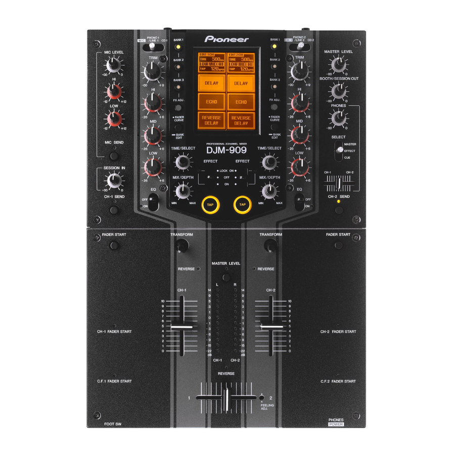
Page 150: Panel Facilities And Specifications
FADER FADER CURVE CURVE + 12 – BANK BANK EDIT EDIT SELECT MIC SEND PROFESSIONAL 2CHANNEL MIXER MASTER TIME/SELECT DJM-909 TIME/SELECT EFFECT EFFECT EFFECT SESSION IN LOCK ON CH-1 CH-2 MIX/DEPTH MIX/DEPTH – CH-1 SEND CH-2 SEND FADER START TRANSFORM... - Page 151 The lever’s setting angle can be changed in 45° increments (changing of the angle should be performed by an authorized 12 MASTER LEVEL dial Pioneer service technician). User to adjust the master output volume level (range of adjustment: 0 dB to –).
- Page 152 FADER CURVE CURVE + 12 – BANK BANK EDIT EDIT SELECT MIC SEND PROFESSIONAL 2CHANNEL MIXER MASTER TIME/SELECT TIME/SELECT DJM-909 EFFECT EFFECT EFFECT SESSION IN LOCK ON CH-1 CH-2 MIX/DEPTH MIX/DEPTH – CH-1 SEND CH-2 SEND TRANSFORM TRANSFORM FADER START...
- Page 153 Use to adjust the time parameters of effects applied to CH-1 (changing of the angle should be performed by an authorized (rotate clockwise to lengthen, counterclockwise to shorten). Pioneer service technician). When the effect select menu is displayed, causes the effects list to scroll.
- Page 154 FADER FADER CURVE CURVE + 12 – BANK BANK EDIT EDIT SELECT MIC SEND PROFESSIONAL 2CHANNEL MIXER MASTER TIME/SELECT DJM-909 TIME/SELECT EFFECT EFFECT EFFECT SESSION IN LOCK ON CH-1 CH-2 MIX/DEPTH MIX/DEPTH – CH-1 SEND CH-2 SEND FADER START TRANSFORM...
- Page 155 Front Panel FADER REVERSE FADER START PHONES CH-1 C.F. CH-2 C.F. 1 CH-1 C.F. 2 CH-2 PROFESSIONAL 2CHANNEL MIXER DJM-909 FADER CURVE POWER CH-1 CROSS FADER 1 CROSS FADER 2 CH-2 FOOT SW FADER CUT LAG CH-1 CH-2 52 FADER REVERSE switches...
- Page 156 69 CH-1 PLAYER CONTROL jack SEND) are set to On, these jacks output the MIC, CH-1, and CH-2 When a Pioneer DJ CD player is connected to the CH-1 CD jacks, signals to the external effector. a special control cord can be used to connect this jack to the When using an effector with a monaural input, connect it to the L player’s control jack, thus enabling the fader start function.
Need help?
Do you have a question about the DJM-909 and is the answer not in the manual?
Questions and answers