Table of Contents
Advertisement
Quick Links
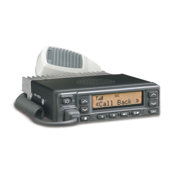
UHF FM TRANSCEIVER
TK-885
SERVICE MANUAL
Cabinet (Lower)
(A01-2166-13)
GENERAL ................................................................. 2
OPERATING FEATURES ......................................... 3
REALIGNMENT ........................................................ 4
INSTALLATION ........................................................ 6
CIRCUIT DESCRIPTION ......................................... 13
SEMICONDUCTOR DATA ..................................... 18
DESCRIPTION OF COMPONENTS ....................... 19
PARTS LIST ............................................................ 21
EXPLODED VIEW .................................................. 30
PACKING ................................................................ 31
Panel assy
Cabinet (Upper)
(A62-0642-03)
(A01-2165-13)
Modular jack
(E08-0877-05)
CONTENTS
© 2000-6 PRINTED IN JAPAN
B51-8535-00 ( N ) 388
ADJUSTMENT ....................................................... 32
PLL/VCO (X58-4722-70) ................................... 40
TX-RX UNIT (X57-6152-70) (A/2)..................... 41
TX-RX UNIT (X57-6152-70) (B/2) ..................... 47
SCHEMATIC DIAGRAM ........................................ 51
BLOCK DIAGRAM.................................................. 59
LEVEL DIAGRAM................................................... 62
TERMINAL FUNCTION ......................................... 64
SPECIFICATIONS................................................... 65
Key top
(K29-5422-02)
Advertisement
Table of Contents

Related Manuals for Kenwood TK-885


Summary of Contents for Kenwood TK-885
-
Page 1: Table Of Contents
UHF FM TRANSCEIVER TK-885 SERVICE MANUAL © 2000-6 PRINTED IN JAPAN B51-8535-00 ( N ) 388 Panel assy Cabinet (Upper) Key top (A62-0642-03) (A01-2165-13) (K29-5422-02) Cabinet (Lower) Modular jack (A01-2166-13) (E08-0877-05) CONTENTS GENERAL ..............2 ADJUSTMENT ............32 OPERATING FEATURES ......... 3 PC BOARD VIEWS REALIGNMENT ............ -
Page 2: General
TK-885 GENERAL 3. PLANNING THE INSTALLATION INTRODUCTION 3-1. General SCOPE OF THIS MANUAL Inspect the vehicle and determine how and where the This manual is intended for use by experienced techni- radio antenna and accessories will be mounted. cians familiar with similar types of commercial grade com- Plan cable runs for protection against pinching or crush- munications equipment. -
Page 3: Operating Features
Control station. The antenna system selection depends 1. Transceiver Controls and Indicators (Fig. 1) on many factors and is beyond the scope of this manual. Your KENWOOD dealer can help you select an antenna sys- 1-1. The Basics tem that will best serve your particular needs. -
Page 4: Realignment
TK-885 OPERATING FEATURES / REALIGNMENT C key (Default setting : None) REALIGNMENT Press to activate its auxiliary function below. Also press to scroll left while viewing stack entries. 1. Modes key (Default setting : None) Press to activate its auxiliary function below. Also press User mode to scroll right while viewing stack entries. - Page 5 6. Firmware Programming Mode model type, when it is written into the flash memory. 6-1. Preface • Change the TK-885 to PC mode, then attach the interface Flash memory is mounted on the TK-885. This allows the cable. TK-885 to be upgraded when new features are released in the future.
-
Page 6: Installation
TK-885 REALIGNMENT / INSTALLATION Notes : INSTALLATION • This mode cannot be entered if the Firmware program- ming mode is set to Disable in the Programming soft- 1. Accessory Connection Cable ware (KPG-62D). • When programming the firmware, it is recommend to... - Page 7 TK-885 INSTALLATION 1-2. KCT-19 Accessory Port Function 1-3. Data Equipment Connection The jumpers must be set to either one for each function. No. (A) No. (B,C,D,E) Name Function Note Otherwise, the radio will not work properly. No function. Microphone ground.
- Page 8 TK-885 INSTALLATION 2. Accessory Terminal (TX-RX Unit) 3. Optional Board Terminal 2-1. External Connector Accessory Terminal Method Terminal is for mounting the option board are provided at the control and TX-RX unit. The table below shows the cor- Connector Function respondence between the board and terminals.
- Page 9 TK-885 INSTALLATION DEO RD2 5C C4 C3 TD1 FW C2 C1 RSSI TX-RX unit (A/2) Foil side view KCT-19 Contact TXAI KCT-18 TXAO Fig. 5 Control unit (B/2) Foil side view 4-2. Modifying the Transceiver RXAI Modify the transceiver as follows to turn the power or...
- Page 10 KPG-62D to reconfigure the scrambler code. 5-2. Voice Scrambler Board Connection Control unit (B/2) • Modification Foil side view 1. Remove the upper half of the case of the TK-885. 2. Remove R529 and R571 on the Control unit (X57-615 B/ RXAI MPTT Scrambler board...
- Page 11 HR1 (Default) Enable 7. Fitting the Control Panel Upside Down The TK-885 control panel can be fitted upside down, so the transceiver can be mounted with its internal speaker (in the upper half of the case) facing down in your car.
-
Page 12: External Speaker
TK-885 INSTALLATION 2. Fold the flat cable ( ) in the opposite direction ( 8. External Speaker 3. Rotate the control section ( ) 180 degrees ( 8-1. KES-3 : Option 4. Insert the flat cable into the control section connector, The KES-3 is an external speaker for the 3.5-mm-diam-... -
Page 13: Circuit Description
TK-885 CIRCUIT DESCRIPTION The signal passes through a BPF and is down-converted Frequency Configuration with the first local signal by IC200, then converted to the The TX-RX unit incorporates a VCO, based on a fractional first IF signal of 44.85MHz. The first local signal passes... - Page 14 8T, and no signal is transmitted. VCO/PLL Circuit The TK-885 has a VCO for the transmitter and a VCO for the receiver in a sub-unit (A1). They are housed in a solid shielded case and connected to the TX-RX unit through CN101.
- Page 15 TK-885 CIRCUIT DESCRIPTION Power Amplifier Circuit LCD ASSY The transmit output signal from the VCO is amplified to a TX-RX UNIT specified level of the power module (IC400) by the drive block (Q202, Q204, Q205). The amplified signal passes IC508...
- Page 16 Fig. 12 Encode Key Matrix Circuit The TK-885 front panel has ten keys. Each of them is connected to a cross point of a matrix of the KEY1 to KEY7 Decode ports of the microprocessor. The KEY5 to KEY7 ports are The signal (DEO) detected by the TX-RX unit passes always high, while the KEY1 to KEY4 ports are always low.
- Page 17 TK-885 CIRCUIT DESCRIPTION D/A Converter Power Supply Circuit The D/A converter (IC5) is used to adjust TONE and MO When the POWER switch on the control unit is pressed, modulation, beep, AF volume, TV voltage, FC reference volt- the PSW signal goes low. This signal is inverted by Q26 and age, and PC POWER CONTROL voltage level.
-
Page 18: Semiconductor Data
TK-885 SEMICONDUCTOR DATA Microprocessor : 30620M8-394GP (TX-RX Unit IC511) Terminal function Pin No. Name Function Pin No. Name Function LSDOUT Low speed data output. PLL IC data strobe output. HSDOUT High speed data output. Flash memory chip enable. HSDIN High speed data input. -
Page 19: Description Of Components
TK-885 SEMICONDUCTOR DATA / DESCRIPTION OF COMPONENTS Terminal function (TX-RX unit IC8) DESCRIPTION OF COMPONENTS Pin No. Port Name Function Strobe TX-RX Unit (X57-6152-70) (A/2) DATA Ref. No. Use / Function Operation / Condition Clock DC amp FC, TCXO control Audio mute 1. - Page 20 TK-885 DESCRIPTION OF COMPONENTS Ref. No. Use / Function Operation / Condition Ref. No. Use / Function Operation / Condition SB switch Active while Q28 is on IC504 Audio processor Compander, MIC amplifier, ALC, SB SW control Active while Q30 is on, and Q31 is off...
-
Page 21: Parts List
TK-885 PARTS LIST CAPACITORS CC 45 TH 1H 220 J • Capacitor value Color* CC45 010 = 1pF 0 = 22pF 100 = 10pF 1 = Type … ceramic, electrolytic, etc. 4 = Voltage rating Multiplier 101 = 100pF 2 = Shape … round, square, ect. - Page 22 TK-885 PARTS LIST New Parts. indicates safety critical components. L : Scandinavia K : USA P : Canada Parts without Parts No. are not supplied. Y : PX (Far East, Hawaii) T : England E : Europe Les articles non mentionnes dans le Parts No. ne sont pas fournis.
- Page 23 TK-885 PARTS LIST TX-RX UNIT (X57-6152-70) Desti- Desti- Ref. No. Address Parts No. Description Ref. No. Address Parts No. Description parts nation parts nation CK73GB1E103K CHIP C 0.010UF C156,157 CK73GB1E103K CHIP C 0.010UF C92-0722-05 ELECTRO 470UF 25WV C158,159 CC73GCH1H050C CHIP C 5.0PF...
- Page 24 TK-885 PARTS LIST TX-RX UNIT (X57-6152-70) Desti- Desti- Ref. No. Address Parts No. Description Ref. No. Address Parts No. Description parts nation parts nation C275 CC73GCH1H040C CHIP C 4.0PF C525 CK73GB1H103K CHIP C 0.010UF C277 CC73GCH1H080D CHIP C 8.0PF C526...
- Page 25 TK-885 PARTS LIST TX-RX UNIT (X57-6152-70) Desti- Desti- Ref. No. Address Parts No. Description Ref. No. Address Parts No. Description parts nation parts nation C609,610 CK73GB1H103K CHIP C 0.010UF L218 L40-6871-34 SMALL FIXED INDUCTOR (68NH) C613 C92-0606-05 CHIP-TAN 4.7UF 10WV...
- Page 26 TK-885 PARTS LIST TX-RX UNIT (X57-6152-70) Desti- Desti- Ref. No. Address Parts No. Description Ref. No. Address Parts No. Description parts nation parts nation RK73GB1J102J CHIP R 1.0K 1/16W R138 RK73FB2A100J CHIP R 1/10W RK73GB1J103J CHIP R 1/16W R139 R92-0670-05...
- Page 27 TK-885 PARTS LIST TX-RX UNIT (X57-6152-70) Desti- Desti- Ref. No. Address Parts No. Description Ref. No. Address Parts No. Description parts nation parts nation R245 R92-0685-05 CHIP R 1/2W R524 RN73GH1J274D CHIP R 270K 1/16W R250 R92-1252-05 CHIP R 0 OHM...
- Page 28 TK-885 PARTS LIST TX-RX UNIT (X57-6152-70) Desti- Desti- Ref. No. Address Parts No. Description Ref. No. Address Parts No. Description parts nation parts nation R619 R92-1252-05 CHIP R 0 OHM D1-6 DA204U DIODE R620 RK73HB1J102J CHIP R 1.0K 1/16W D1-6...
- Page 29 TK-885 PARTS LIST TX-RX UNIT (X57-6152-70) PLL/VCO (X58-4722-70) Desti- Desti- Ref. No. Address Parts No. Description Ref. No. Address Parts No. Description parts nation parts nation IC503 TA75W558FU MOS IC PLL/VCO (X58-4722-70) IC504 TC35453F MOS IC IC506 BU4066BCFV MOS IC...
-
Page 30: Exploded View
TK-885 EXPLODED VIEW Parts with the exploded numbers larger than 700 are not supplied. -
Page 31: Packing
TK-885 PACKING 51 Microphone 39 Protection bag 12 DC cord (H25-0720-04) (T91-0621-05) 5 Cap (E30-3339-05) (B09-0235-05) 24 Fuse (F51-0016-05) 43 Bracket (J29-0627-23) 37 Inner packing case (H12-1391-03) 42 MIC hanger (J19-1584-05) 47 Screw set 36 Polystyrene foamed fixture (N99-0395-05) (H10-6619-12) -
Page 32: Adjustment
TK-885 ADJUSTMENT Frequency and Signalling Test Mode The set has been adjusted for the frequencies shown in Test Mode Operating Features the following table. When required, re-adjust them follow- This transceiver has a test mode. To enter test mode, ing the adjustment procedure to obtain the frequencies you press [B] key and turn power on. - Page 33 TK-885 ADJUSTMENT • Tuning flow Press [A], now in tuning mode. Use [ C] button to write tuning data through tuning modes, and [System Up/Down] to adjust tuning requirements (1 to 256 appears on LCD). FREQ xxx Use [D ] button to select the adjustment item through tuning modes.
- Page 34 TK-885 ADJUSTMENT Test Equipment Required for Alignment Test Equipment Major Specifications 1. Standard Signal Generator Frequency Range 400 to 470MHz (SSG) Modulation Frequency modulation and external modulation Output –127dBm/0.1µV to greater than –7dBm/100mV 2. Power Meter Input Impedance 50Ω Operation Frequency...
- Page 35 Repair Jig (Chassis) • EEPROM Use jig (Part No. : A10-4010-02) for repairing the TK-885. The tuning data (Deviation, Squelch, etc.) for the The jig facilitates the voltage check when the voltage on the EEPROM, is stored in memory. When parts are changed, component side TX-RX unit is checked during repairs.
- Page 36 TK-885 ADJUSTMENT Receiver Section Measurement Adjustment Item Condition Specifications/Remarks Test- Unit Terminal Unit Parts Method equipment 1. Discriminator 1) Set test mode Rear TX-RX L6 AF output voltage CH : CH1 - Sig1 panel (A/2) maximum. SSG output : –53dBm AF VTVM AF : 1.4V/4Ω...
- Page 37 TK-885 ADJUSTMENT Measurement Adjustment Item Condition Specifications/Remarks Test- Unit Terminal Unit Parts Method equipment 7. QT check 1) Set test mode Rear Check Squelch must be opened. CH : CH1 - Sig5 panel SSG freq’ : 455.050MHz AF VTVM SSG MOD Distortion (EXT.SP)
- Page 38 TK-885 ADJUSTMENT Measurement Adjustment Item Condition Specifications/Remarks Test- Unit Terminal Unit Parts Method equipment 5. Power check 1) Set test mode Power meter Check 25W±1W, 8A or less CH : CH1 - Sig1 CH2 - Sig1 Ammeter DC IN CH3 - Sig1 PTT : ON 6.
- Page 39 TK-885 ADJUSTMENT Measurement Adjustment Item Condition Specifications/Remarks Test- Unit Terminal Unit Parts Method equipment ±50Hz 10. DQT 1) Set test mode Power meter Rear 0.35kHz deviation Select “DQT” in tuning mode. Deviation panel “L DQT” meter Deviation meter filter Oscilloscope...
-
Page 40: Pc Board Views
TK-885 PC BOARD VIEWS PLL/VCO (X58-4722-70) Component side view J72-0733-02 C115 C119 CN101 L105 L109 L103 R104 C104 R119 C117 C122 L107 Q105 Q106 R109 R118 Q102 R111 R110 R115 C125 R114 R107 C126 R108 Q104 R103 C102 C129 L110... -
Page 41: Tx-Rx Unit (X57-6152-70) (A/2)
TK-885 PC BOARD VIEW TX-RX UNIT (X57-6152-70) (A/2) Component side view Ref. No. Address Ref. No. Address Ref. No. Address Ref. No. Address Ref. No. Address Q203 D205 IC10 Q300 D206 IC11 Q301 D211 IC14 Q302 D212 Component side IC400... - Page 42 TK-885 PC BOARD VIEW TX-RX UNIT (X57-6152-70) (A/2) Foil side view Ref. No. Address Ref. No. Address Ref. No. Address Ref. No. Address Ref. No. Address Ref. No. Address Ref. No. Address IC13 Q26 10C Q205 D17 13D IC15 IC200 12Q...
- Page 43 TK-885 Ref. No. Address Ref. No. Address Ref. No. Address Ref. No. Address Ref. No. Address Ref. No. Address Ref. No. Address Ref. No. Address PC BOARD VIEW IC14 Q203 D200 TX-RX UNIT (X57-6152-70) (A/2) Component side view + Foil side...
-
Page 44: Tx-Rx Unit (X57-6152-70) (B/2)
TK-885 PC BOARD VIEWS TX-RX UNIT (X57-6152-70) (B/2) Component side view J72-0725-12 B/2 D512 R514 D517 R710 C712 R517 R510 C527 C710 C518 C583 R526 R713 L507 IC710 R525 R682 IC502 C524 R572 D511 IC501 IC508 C592 R531 R714 R502... - Page 45 TK-885 PC BOARD VIEW TX-RX UNIT (X57-6152-70) (B/2) Component side view + Foil side J72-0725-12 B/2 D512 R520 R514 D517 R710 C607 C712 R517 MPTT C516 R518 R510 C515 C527 C710 C518 C583 R525 RXAO R680 R521 R526 R713 L507...
-
Page 46: Schematic Diagram
TK-885 SCHEMATIC DIAGRAM Note : Components marked with a dot (·) are parts of patterun 1. - Page 47 TK-885 Note : Components marked with a dot (·) are parts of patterun 1. SCHEMATIC DIAGRAM...
-
Page 48: Block Diagram
TK-885 TK-885 TK-885 BLOCK DIAGRAM... -
Page 49: Level Diagram
TK-885 TK-885 LEVEL DIAGRAM Receiver Section –88.0dBm –95.0dBm –118.0dBm –122.0dBm –116.0dBm –116.0dBm –108.0dBm –121.0dBm –109.0dBm 62mVrms 30mVrms 820mVrms 820mVrms 16mVrms 0.45Vrms SG input level for 12dB SINAD are obtained measured by AF VTVM connecting SG to each point via a 0.01µF capacitor. -
Page 50: Terminal Function
TK-885 TERMINAL FUNCTION CN7 (TX-RX Unit) ← → CN502 (Control Unit) CN101 (VCO) ← → TX-RX Unit Pin No. Name Function Pin No. Name Function No function. Switched transmit input. H : Transmit TX/RX switch. H : Receive RF output. -
Page 51: Specifications
TK-885 SPECIFICATIONS GENERAL Frequency Range ........ 450 to 470MHz Number of Channels ......Trunking mode : Maximum 1023 channels Conventional mode : Maximum 32 channels Channel Spacing ......... 12.5kHz Input Voltage ........13.6V negative ground Current Drain ........0.4A on standby 1.0A on receive... - Page 52 Mechelsesteenweg 418 B-1930 Zaventem, Belgium KENWOOD ELECTRONICS FRANCE S.A. 13, Boulevard Ney, 75018 Paris, France KENWOOD ELECTRONICS U.K. LIMITED KENWOOD House, Dwight Road, Watford, Herts., WD1 8EB United Kingdom KENWOOD ELECTRONICS EUROPE B.V. Amsterdamseweg 37, 1422 AC Uithoorn, The Netherlands KENWOOD ELECTRONICS ITALIA S.p.A.
Need help?
Do you have a question about the TK-885 and is the answer not in the manual?
Questions and answers