Advertisement
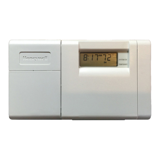
The T8132C Programmable Thermostat provides en-
ergy savings for heating and cooling applications. Separate
programs can be set for weekdays and weekends.
Check Table 1 to make sure the T8132C Thermostat is
compatible with the intended system.
TABLE 1—COMPATIBILITY CHART.
System Type
Gas—Standing Pilot
Gas—Electronic Ignition
Gas-Fired Boilers
Gas—Millivolt
Oil-Fired Boilers
Oil-Fired Furnace
Electric Furnace
Electric Air Conditioning
Baseboard Electric
(120/240 Line Volt)
Heat pumps/Multistage Equipment
Not compatible with any 120/240 volt circuit.
Not designed for steam or gravity systems.
a
Compatible with 2-wire Honeywell zone valves. Isolating
relay required for 3-wire thermostats for zone valves. Not
compatible with 2-wire White Rodgers no. 1361 Valves.
WHEN INSTALLING THIS PRODUCT...
1. Read these instructions carefully. Failure to fol-
low instructions can damage product or cause a hazardous
condition.
2. Check the ratings given in the instructions and on
the product to make sure the product is suitable for your
application.
3. Make sure installer is a trained, experienced service
technician.
4. After completing installation, use these instructions
to check out product operation.
CAUTION
Disconnect power supply before wiring to pre-
vent electrical shock or equipment damage.
Programmable Thermostats
Application
Compatible
With T8131C
Yes
Yes
a
Yes
No
a
Yes
Yes
Yes
Yes
No
No
Installation
G. S. • 1-95 • ©Honeywell Inc. 1995 • Form Number 69-0889
LOCATION
Locate the thermostat about 5 ft (1.5m) above the floor
in an area with good air circulation at average temperature.
Do not mount the thermostat where it may be affected by:
— drafts or dead spots behind doors and in corners.
— hot or cold air ducts.
— concealed pipes and chimneys.
— unheated (uncooled) areas such as an outside wall
behind the thermostat.
MOUNT THERMOSTAT MOUNTING PLATE
(FIG. 1)
Position mounting plate on wall. Use spirit level to make
sure mounting plate is level. Use a pencil to mark the two
mounting holes.
Level for appearance only; thermostat functions prop-
erly even when not level. Tighten mounting screws.
Remove mounting plate from wall, and drill 3/16 inch
holes in wall (if drywall) as marked. For firmer material
such as plaster or wood, drill 7/32 inch holes. Gently tap
anchors (provided) into drilled holes until flush with the
wall.
Reposition mounting plate over holes, pulling wires
through wiring opening. Loosely insert two mounting screws
into holes.
Fig. 1—Mounting thermostat mounting plate.
WIRES THROUGH
WALL OPENING
WALL
WIRING
All wiring must comply with all applicable electrical
codes, ordinances, and regulations. Follow instructions
provided with the controlled equipment.
Run the required number of wires to the thermostat
location (check the appropriate wiring diagram). Refer to
Fig. 3 through 6 for typical wiring diagrams.
In 5-wire installations only, be sure to remove the fac-
tory-installed jumper connecting terminals R and Rc.
1
T8132C
WALL
ANCHORS (2)
MOUNTING
PLATE
MOUNTING
SCREWS (2)
M1718
69-0889
Advertisement
Table of Contents

Related Manuals for Honeywell T8132C


Summary of Contents for Honeywell T8132C
-
Page 1: Programmable Thermostats
Fig. 3 through 6 for typical wiring diagrams. In 5-wire installations only, be sure to remove the fac- tory-installed jumper connecting terminals R and Rc. G. S. • 1-95 • ©Honeywell Inc. 1995 • Form Number 69-0889 69-0889... -
Page 2: Adjust Fan Operation Switch, As Required
Loosen the terminal screws and slip each wire beneath its matching terminal. See Fig. 2 for wiring insertion tech- Fig. 5—5-wire heat/cool application (jumper removed). niques. Tighten terminals securely. Plug the hole in the wall with insulation to help prevent 5-WIRE HEAT/COOL (JUMPER REMOVED) drafts from adversely affecting thermostat operation. -
Page 3: Install Batteries
NOTE: The T8132C Thermostat does not have a setting for TABLE 2—BURNER ON-TIME ADJUSTMENTS. steam/gravity air. Cycles would not be long enough for If you want a longer on-time, readjust the screws as accurate temperature control. follows (refer to the heating system table in Fig. 7):... -
Page 4: Checkout And Settings
Fig. 10—Mounting the thermostat on the subbase. ENGAGE TABS AT TOP OF PRESS LOWER EDGE NOTE: THERMOSTAT AND MOUNTING PLATE. OF CASE TO LATCH. FOR T8132C SWING OPEN COVER TO CHECK OPERATION. M7493 Checkout and Settings CHECKOUT After the thermostat is mounted on the subbase, check operation as follows:... -
Page 5: Troubleshooting
Press key until the setting is about 10°F Warmer (6°C) above room temperature. The cooling equipment and fan should stop. Cool Heat Move the system switch to OFF with the fan Auto switch remaining at AUTO. The system and fan should be off. SETTINGS AND ADJUSTMENTS Set the Fan and System Switches Auto... - Page 6 Remove batteries. Wait one hour. Install fresh alkaline batteries. fresh batteries have been installed Home and Building Control Home and Building Control Helping You Control Your World Honeywell Inc. Honeywell Limited—Honeywell Limitée 1985 Douglas Drive North 740 Ellesmere Road Golden Valley, MN 55422 Scarborough, Ontario M1P 2V9...
Need help?
Do you have a question about the T8132C and is the answer not in the manual?
Questions and answers