Chapters
Table of Contents

Related Manuals for HP msm4 series


Summary of Contents for HP msm4 series
- Page 1 HP MSM3xx / MSM4xx Access Points Installation and Getting Started Guide ProCurve 5400zl Switches HP MSM3xx / MSM4xx Access Points Installation and Getting Started Guide Installation and Getting Started Guide Power over Ethernet...
- Page 3 HP MSM3xx / MSM4xx Access Points Installation and Getting Started Guide...
- Page 4 Publication Number material. 5998-1234 The only warranties for HP products and services are set forth May 2011 in the express warranty statements accompanying such products and services. Nothing herein should be construed as Applicable Products constituting an additional warranty.
-
Page 5: Table Of Contents
Controlled mode and autonomous mode ............1-3 Controlled mode .....................1-3 Autonomous mode..................1-3 Important terms .....................1-3 Conventions ........................1-4 Management tool ....................1-4 Warnings and cautions ..................1-4 HP support ........................1-5 Before contacting support..................1-5 Online documentation ....................1-5 MSM410 Introduction ........................2-2 Package contents....................2-2 Hardware overview......................2-3 Status lights ......................2-4 Autonomous mode..................2-4... - Page 6 Contents Installation ........................2-7 Mounting on a wall ....................2-7 Mounting on a wall-mounted electrical box ............2-7 Mounting on a suspended ceiling ................2-8 Attaching the MSM410 to the mounting bracket ..........2-8 Installing in a plenum....................2-9 Powering the MSM410 ..................2-9 Initial configuration (autonomous mode)..............2-9 Step 1: Configure your computer ..............2-10 Step 2: Connect the cables and power on the MSM410 ........2-10 Step 3: Switch the MSM410 to autonomous mode ..........2-10...
- Page 7 Contents Safety........................3-8 Installation ........................3-9 Mounting on a wall ....................3-9 Mounting on a suspended ceiling ................3-9 Installing in a plenum..................3-10 Antenna position....................3-10 Powering the MSM422 ..................3-10 Initial configuration (autonomous mode)...............3-11 Step 1: Configure your computer ..............3-11 Step 2: Connect the cables and power-on the MSM422 ........3-11 Step 3: Switch the MSM422 to autonomous mode ..........3-12 Step 4: Log in ......................3-12 Step 5: Assign an IP address to the MSM422............3-13...
- Page 8 Contents Safety........................4-6 Installation ........................4-6 Installing in a plenum....................4-6 Powering the MSM310 ..................4-6 Initial configuration (autonomous mode)..............4-6 Step 1: Configure your computer ................4-7 Step 2: Connect the cables and power on the MSM310 ........4-7 Step 3: Switch the MSM310 to autonomous mode ..........4-8 Step 4: Log in ......................4-8 Step 5: Assign an IP address to the MSM310............4-9 Step 6: Test the wireless network................4-9...
- Page 9 Initial configuration (autonomous mode)...............5-10 Step 1: Configure your computer ..............5-11 Step 2: Connect the cables and power on the MSM310-R ......5-11 Step 3: Switch the MSM310-R to autonomous mode ........5-11 Step 4: Log in ......................5-12 Step 5: Assign an IP address to the MSM310-R..........5-12 Step 6: Test the wireless network..............5-13 Step 7: Perform additional configuration ............5-13 To enable access to other resources ............5-14...
- Page 10 Step 3: Switch the MSM320 to autonomous mode ..........6-8 Step 4: Log in ......................6-8 Step 5: Assign an IP address to the MSM320............6-9 Step 6: Test the wireless network................6-9 Step 7: Perform additional configuration ............6-10 To enable access to other resources ............6-10 MSM320-R Introduction ........................7-3 Package contents....................7-3...
- Page 11 To enable access to other resources ............7-14 MSM335 Introduction ........................8-2 Package contents....................8-2 Hardware overview......................8-3 Status lights ......................8-4 Autonomous mode..................8-4 Controlled mode .....................8-4 Radios and antennas .....................8-5 Ports ........................8-5 Reset button ......................8-5 Important information to read before installing ............8-6 For indoor installation only................8-6 PROFESSIONAL INSTALLATION REQUIRED...........8-6 Surge protection and grounding ................8-6 Cabling ........................8-6...
- Page 12 Regulatory information Notice for U.S.A.....................9-2 Manufacturer's FCC Declaration of Conformity Statement......9-2 FCC Class B statement...................9-2 FCC Class A statement...................9-3 Exposure to Radio Frequency Radiation.............9-3 Notice for Canada....................9-3 Notice for the European Community..............9-4 Disposal of Waste Equipment by Users in Private Household in the European Union ....................9-5 Supported External Antennas................9-5 Notice for Brazil, Aviso aos usuários no Brasil ..........9-6...
-
Page 13: Introduction
Chapter 1: Introduction Introduction Contents About this guide ......................1-2 Products covered....................1-2 Important terms .....................1-3 Conventions ........................1-4 HP support ........................1-5 Before contacting support..................1-5 Online documentation ....................1-5... -
Page 14: About This Guide
Introduction About this guide About this guide This guide provides the following information for MSM Access Points (APs): Hardware overview Safety and regulatory information Installation procedure For those using an AP in autonomous mode, an initial configuration procedure is also provided. -
Page 15: Controlled Mode And Autonomous Mode
The following terms are used in this guide. Term Description AP or MSM AP Refers to any HP MSM3xx or MSM4xx Access Point. Specific model references are used where appropriate. Controller Refers to any HP MSM7xx Controller, including both Access Controller... -
Page 16: Conventions
Introduction Conventions Conventions Management tool This guide uses specific syntax when directing you to interact with the management tool user interface. Refer to the following image for identification of key user-interface elements and then the table below for example directions: Main menu Sub-menu Example directions in this guide... -
Page 17: Hp Support
ProCurve. Additionally, your HP-authorized networking products reseller can provide you with assistance. Before contacting support To make the support process most efficient, before calling your networking dealer or HP Support, you first should collect the following information: Collect this information Where to find it Product identification. - Page 18 Introduction Online documentation...
- Page 19 Chapter 2: MSM410 MSM410 Contents Introduction ........................2-2 Package contents....................2-2 Hardware overview......................2-3 Status lights ......................2-4 Ports ........................2-5 Radio and antenna....................2-5 Reset button ......................2-5 Important information to read before installing ............2-6 Cabling ........................2-6 Plenum installation....................2-6 Country of use......................2-6 Safety........................2-6 Installation ........................2-7 Mounting on a wall ....................2-7 Mounting on a wall-mounted electrical box ............2-7 Mounting on a suspended ceiling ................2-8 Attaching the MSM410 to the mounting bracket ..........2-8...
-
Page 20: Msm410
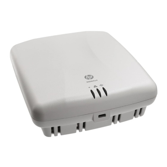
MSM410 Introduction Introduction This chapter shows you how to get started using the MSM410 (E-MSM410) Access Point. The MSM410 is a Wi-Fi Alliance authorized Wi-Fi CERTIFIED 802.11a/b/g and 802.11n product. The Wi-Fi CERTIFIED Logo is a certification mark of the Wi-Fi Alliance. -
Page 21: Hardware Overview
MSM410 Hardware overview Hardware overview MSM410 key components are identified as follows: ➀ ➁ Front view 1: Status Lights (left to right) Power, Ethernet, Radio 2: Cable lock hole ➀ ➁ ➁ Back view 1: Cable channel 2: Mounting bracket tab slot ➁... -
Page 22: Status Lights
The MSM410 is starting up. If the Power light continues to blink after several minutes, it indicates that the software failed to load. Reset or power cycle the MSM410. If this condition persists, contact HP Support. Ethernet The port is not connected or there is no activity. -
Page 23: Ports
MSM410 Hardware overview Once the discovery process is complete, and the MSM410 has established a secure management tunnel to a controller, the Power light remains on and the Ethernet and Radio lights blink to indicate the presence of traffic. Ports The MSM410 provides two ports. -
Page 24: Important Information To Read Before Installing
MSM410 Important information to read before installing Important information to read before installing For indoor installation only. PROFESSIONAL INSTALLATION REQUIRED Prior to installing or using the MSM410, consult with a professional installer trained in RF installation and knowledgeable in local regulations including building and wiring codes, safety, channel, power, indoor/outdoor restrictions, and license requirements for the intended country. -
Page 25: Installation
MSM410 Installation Handle exposed metal components of the network with caution. The MSM410 is powered-on when connected to a PoE power source. The MSM410 and all interconnected equipment must be installed indoors within the same building (except for outdoor models / antennas), including all PoE-powered network connections as described by Environment A of the IEEE 802.3af standard. -
Page 26: Mounting On A Suspended Ceiling
MSM410 Installation 1. Disconnect power and take any other needed security precautions. ➀ 2. Remove the electrical box cover and any contents. ➁ ➁ 3. Pull the Ethernet cable down into the box and then ➂ through the hole in the bracket. 4. -
Page 27: Installing In A Plenum
2-6. Powering the MSM410 The MSM410 can be powered by: A 10/100 or 10/100/1000 PoE-enabled switch. PoE-enabled switches are available from HP. An HP 1-Port Power Injector (J9407A). Caution If the MSM410 will be powered by a user-supplied PoE power injector, use only a gigabit- compatible power injector. -
Page 28: Step 1: Configure Your Computer
MSM410 Initial configuration (autonomous mode) Note Do not power-on the MSM410 until directed. Step 1: Configure your computer 1. Disconnect your computer LAN port and configure it to use a static IP address in the range 192.168.1.2 to 192.168.1.254, and a subnet mask of 255.255.255.0. Set the default gateway to 192.168.1.1, and DNS server to 192.168.1.1. -
Page 29: Step 4: Log In
MSM410 Initial configuration (autonomous mode) Note To avoid a delay after switching modes, clear the ARP (address resolution protocol) cache on your computer. In Windows for example, from the Windows Start menu, select Run and enter “arp -d” (without the quotes). Select OK. Step 4: Log in 1. -
Page 30: Step 6: Test The Wireless Network
For example, in Windows Vista from the Start menu, select Connect to, and then HP from the list of available wireless networks. You may have to wait a short time for this wireless network name to appear in the wireless networks list. -
Page 31: Step 7: Perform Additional Configuration
By default, the MSM410 only permits traffic that is addressed to the default gateway on the network (which enables you to connect to the Internet). To enable access to other resources: 1. Select VSC > Profiles and then select the HP profile. 2. On the Add/Edit Virtual Service Community page clear the Wireless security filters checkbox. - Page 32 MSM410 Initial configuration (autonomous mode) 2-14...
-
Page 33: Reset Button
Chapter 3: MSM422 MSM422 Contents Introduction ........................3-3 Package contents....................3-3 Hardware overview......................3-4 Status lights ......................3-5 Ports ........................3-6 Radios and antennas .....................3-6 Reset button ......................3-7 Important information to read before installing ............3-7 Surge protection and grounding ................3-7 Cabling ........................3-7 Plenum installation....................3-7 Country of use......................3-8 External antennas....................3-8 Power supply......................3-8 Safety........................3-8... -
Page 34: Msm422
MSM422 Step 6: Test the wireless network..............3-13 Step 7: Perform additional configuration ............3-14... -
Page 35: Introduction
MSM422 Introduction Introduction This chapter shows you how to get started using the MSM422 (E-MSM422) Access Point. The MSM422 is a Wi-Fi Alliance authorized Wi-Fi CERTIFIED 802.11a/b/g and 802.11n product. The Wi-Fi CERTIFIED Logo is a certification mark of the Wi-Fi Alliance. Package contents One MSM422 Access Point ... -
Page 36: Hardware Overview
MSM422 Hardware overview Hardware overview MSM422 key components are identified as follows: ➁ ➀ Flaps open ➂ ➃➄➅ ➆➇➈ ➉ Front view 1: Antenna B connector 5: Info light 9: Radio 2 - 802.11 a/b/g 2: Antenna D connector 6: Ethernet light 10: Radio 1 antenna flap 3: Radio 2 antenna flap 7: Radio 1 - 802.11n... -
Page 37: Status Lights
The MSM422 is starting up. If the Power light continues to blink after several minutes, it indicates that the software failed to load. Reset or power cycle the MSM422. If this condition persists, contact HP Support. Info The MSM422 is fully operational. -
Page 38: Ports
The MSM422 has two radios. The lower flap contains three antennas (MIMO) for Radio 1, which by default is set to 802.11n (5 GHz) mode. The upper flap contains two antennas for Radio 2, which by default is set to 802.11b/g mode. Optional external antennas are available from HP. Radio mode Antenna... -
Page 39: Reset Button
Failure to do so may result in personal injury, fire, equipment damage, or a voided warranty. The HP hardware warranty provides no protection against damage caused by static discharge or a lightning strike. -
Page 40: Country Of Use
The MSM422 is intended to have its power supplied by a Listed Information Technology Equipment AC Adapter, Wall Industries Inc., Model GPSU30A-8, rated output 33-50 Vdc, 0.91- 0.61 A, available as HP part number J9406A. As an alternative, the MSM422 may be connected to an external PoE source. -
Page 41: Installation
MSM422 Installation Installation This section describes the various installation options for the MSM422. Mounting on a wall 1. Using the supplied wall anchors and screws, attach the mounting bracket vertically to a wall with the flange at the bottom. Use at least two opposing screw holes. Leave enough space above the MSM422 for cable access and antenna flap extension. -
Page 42: Installing In A Plenum
For ceiling mount, close the flaps or point them toward the floor (90 Powering the MSM422 The MSM422 can be powered by: A 10/100 or 10/100/1000 PoE-enabled switch. PoE-enabled switches are available from HP. An HP 1-Port Power Injector (J9407A). An HP MSM422 Power Supply (J9406A). -
Page 43: Initial Configuration (Autonomous Mode)
MSM422 Initial configuration (autonomous mode) Initial configuration (autonomous mode) This procedure describes how to switch a factory-default MSM422 to autonomous mode and then perform its initial configuration that enables you to establish a wireless connection through the MSM422 to the Internet. In autonomous mode, the MSM422 is managed via its Web-based management tool as described in this section. -
Page 44: Step 4: Log In
MSM422 Initial configuration (autonomous mode) 2. Power on the MSM422: If using a PoE switch or injector, power it on. If using a power supply, connect it to the MSM422 then power on the supply. Initially, the MSM422 power light will blink once every two seconds. Wait approximately a minute until it begins blinking once per second before proceeding to the next step. -
Page 45: Step 5: Assign An Ip Address To The Msm320
MSM422 Initial configuration (autonomous mode) The management tool is organized with menus and sub-menus. Instructions for making menu selections, such as “select Wireless > Local mesh” instruct you to select the Wireless menu and then the Local mesh sub-menu, as follows: Main menu Sub-menu Step 5: Assign an IP address to the MSM422... -
Page 46: Step 7: Perform Additional Configuration
For example, in Windows Vista from the Start menu, select Connect to, and then HP from the list of available wireless networks. You may have to wait a short time for this wireless network name to appear in the wireless networks list. - Page 47 Chapter 4: MSM310 MSM310 Contents Introduction ........................4-2 Package contents....................4-2 Hardware overview......................4-2 Status lights ......................4-2 Ethernet ports ......................4-4 Reset button ......................4-4 Radios and antennas .....................4-4 Important information to read before installing ............4-4 Surge protection and grounding ................4-5 Cabling ........................4-5 Plenum installation....................4-5 Country of use......................4-5 External Antennas ....................4-5 Power supply......................4-5...
-
Page 48: Introduction
MSM310 Introduction Introduction This chapter shows you how to get started using the MSM310 (E-MSM310) Access Point. The MSM310 is a Wi-Fi Alliance authorized Wi-Fi CERTIFIED 802.11a/b/g product. The Wi-Fi CERTIFIED Logo is a certification mark of the Wi-Fi Alliance. The MSM310 is certified under the SpectraLink Voice Interoperability for Enterprise Wireless (VIEW) VIEW Certification Program when it operates in autonomous mode or in controlled mode in... -
Page 49: Autonomous Mode
The MSM310 is starting up. If the Power light continues to blink after several minutes, it indicates that the software failed to load. Reset or power cycle the MSM310. If this condition persists, contact HP Support. Ethernet The port is not connected or there is no activity. -
Page 50: Radios And Antennas
RP-SMA plugs. Antennas can be mounted directly on the MSM310. When a single antenna is used per radio, it is recommended to connect it to the Main antenna connector. Note Optional external antennas are available from HP. Important information to read before installing For indoor installation only. -
Page 51: Surge Protection And Grounding
The MSM310 is intended to have its power supplied by a Listed Information Technology Equipment AC Adaptor, Sparkle Co. Inc., Models FSP015-1AD201A or FSP015-DYAA1xx, rated output 5 Vdc, 3A (marked Class 2 or LPS) available as HP part number J9405A. As an alternative, the MSM310 may be connected to an external PoE source. -
Page 52: Safety
Plenum installation on page 4-5. Powering the MSM310 The MSM310 can be powered by: A PoE-enabled switch. PoE-enabled switches are available from HP. An HP 1-Port Power Injector (J9407A) An HP MSM32x Power Supply (J9405A). Initial configuration (autonomous mode) -
Page 53: Step 1: Configure Your Computer
MSM310 Initial configuration (autonomous mode) In autonomous mode, the MSM310 is managed via its Web-based management tool as described in this section. This requires at least Microsoft Internet Explorer 7/8 or Mozilla Firefox 3.x. For controlled mode configuration, see Working with controlled APs in the MSM7xx Controllers Management and Configuration Guide. -
Page 54: Step 4: Log In
MSM310 Initial configuration (autonomous mode) Step 3: Switch the MSM310 to autonomous mode Note A factory-default MSM310 is assumed. 1. In a Web browser, enter the address: https://192.168.1.1. 2. A security certificate warning is displayed the first time you connect to the management tool. -
Page 55: Step 5: Assign An Ip Address To The Msm320-R
MSM310 Initial configuration (autonomous mode) Step 5: Assign an IP address to the MSM310 By default the MSM310 operates as a DHCP client. This means that if the network has a DHCP server, the MSM310 will automatically receive a new IP address in place of its default address of 192.168.1.1 upon connecting to the network. -
Page 56: To Enable Access To Other Resources
For example, in Windows Vista from the Start menu, select Connect to, and then HP from the list of available wireless networks. You may have to wait a short time for this wireless network name to appear in the wireless networks list. - Page 57 Chapter 5: MSM310-R MSM310-R Contents Introduction ........................5-2 Package contents....................5-2 Protection equipment needed................5-2 Hardware overview......................5-3 Radios and antennas .....................5-4 Ethernet port......................5-4 Resetting to factory defaults ................5-4 Important information to read before installing ............5-4 Surge protection and grounding ................5-4 Cabling ........................5-5 Country of use......................5-5 External antennas....................5-5 Safety........................5-5 Installation ........................5-6...
-
Page 58: Introduction
In addition to the items supplied with the MSM310-R, protection equipment will be required according to your electrical code. For example: Antenna surge suppressor: HP Antenna Lightning Arrester, J8996A. Ethernet surge suppressor: Weatherproof PoE compatible 10/100 base-T CAT5... -
Page 59: Hardware Overview
MSM310-R Hardware overview Hardware overview MSM310-R key components are identified as follows: ➀ ➁ ➃ ➂ ➂ ➃ ➄ MSM310-R 1: Main antenna 2: Auxiliary antenna 3: Surge suppressors (not exactly as ➅ shown) 4: Gas tube cover 5: Weatherproof RJ-45 connector 6: Pole-mount bracket 7: Wall-mount bracket ➆... -
Page 60: Radios And Antennas
Make sure that proper lightning surge protection and grounding precautions are taken according to local electrical code. Failure to do so may result in personal injury, fire, equipment damage, or a voided warranty. The HP hardware warranty provides no protection against damage caused by static discharge or a lightning strike. -
Page 61: Cabling
For specific power limits for your country, consult the Antenna Power-Level Setting Guide (for MSM Products) available from www.hp.com/networking/support and for Product Brand, select ProCurve. To set the radio transmission power level, for controlled access points see Transmit power control in the MSM7xx Controllers Management and Configuration Guide. -
Page 62: Installation
MSM310-R Installation Installation Warning The MSM310-R must be installed with the antennas pointing straight up. Damage caused by water ingress through the RJ-45 connector as a result of the MSM310-R being improperly installed or the improper assembly or attachment of the weatherproof RJ-45 connector, is not covered by the warranty. -
Page 63: Step 2: Install Cabling
2. If your Ethernet cable already has an RJ-45 connector on the end that will connect to the HP equipment, remove the RJ-45 connector by cutting the cable at least 1.2 cm (.5 inch) before the RJ-45 connector. Be sure to make a clean cut with a pair of sharp angle cutters. -
Page 64: Step 4: Install The Msm310-R
MSM310-R Installation 7. Remove the white backing paper from one of the RJ-45 Gaskets (8) and press the glued side onto the Body (6) being very careful to align the gasket with the RJ-45 connector shape on the Body (6). 8. - Page 65 Attach the two supplied antennas. Note If installing an optional HP antenna, first attach the lightning arrester to the MSM310-R, attach the antenna adapter to the arrester, then attach the antenna connector to the adapter. See also the antenna documentation.
-
Page 66: Initial Configuration (Autonomous Mode)
Ethernet surge suppressor. Step 5: Power the MSM310-R The MSM310-R can be powered by: A PoE-enabled switch. PoE-enabled switches are available from HP. An HP 1-Port Power Injector (J9407A). Initial configuration (autonomous mode) This procedure describes how to switch a factory-default MSM310-R to autonomous mode and then perform its initial configuration that enables you to establish a wireless connection through the MSM310-R to the Internet. -
Page 67: Step 1: Configure Your Computer
MSM310-R Initial configuration (autonomous mode) Step 1: Configure your computer 1. Disconnect your computer LAN port and configure it to use a static IP address in the range 192.168.1.2 to 192.168.1.254, and a subnet mask of 255.255.255.0. Set the default gateway to 192.168.1.1, and DNS server to 192.168.1.1. For example to do this in Windows Vista, use Control Panel >... -
Page 68: Step 4: Log In
MSM310-R Initial configuration (autonomous mode) Step 4: Log in 1. Wait until the login page appears, then specify admin for both Username and Password. Select Login. 2. On the License Agreement page, read the agreement and select Accept License Agreement. 3. -
Page 69: Step 7: Perform Additional Configuration
For example, in Windows Vista from the Start menu, select Connect to, and then HP from the list of available wireless networks. You may have to wait a short time for this wireless network name to appear in the wireless networks list. -
Page 70: To Enable Access To Other Resources
By default, the MSM310-R only permits traffic that is addressed to the default gateway on the network (which enables you to connect to the Internet). To enable access to other resources: 1. Select VSC > Profiles and then select the HP profile. 2. On the Add/Edit Virtual Service Community page clear the Wireless security filters checkbox. - Page 71 Chapter 6: MSM320/MSM325 MSM320/MSM325 Contents Introduction ........................6-2 Package contents....................6-2 Hardware overview......................6-2 Status lights ......................6-2 Ethernet ports ......................6-4 Reset button ......................6-4 Radios and antennas .....................6-4 Important information to read before installing ............6-4 Surge protection and grounding ................6-5 Cabling ........................6-5 Plenum installation....................6-5 Country of use......................6-5 External Antennas ....................6-5 Power supply......................6-5...
-
Page 72: Introduction
MSM320/MSM325 Introduction Introduction This chapter shows you how to get started using the MSM320 (E-MSM320) Access Point. This chapter also applies to the MSM325 (E-MSM325) Access Point with integrated sensor. Only the term "MSM320" is used throughout the rest of this chapter. It equally applies to the MSM325. - Page 73 The MSM320 is starting up. If the Power light continues to blink after several minutes, it indicates that the software failed to load. Reset or power cycle the MSM320. If this condition persists, contact HP Support. Ethernet The port is not connected or there is no activity.
-
Page 74: Reset Button
RP-SMA plugs. Antennas can be mounted directly on the MSM320. When a single antenna is used per radio, it is recommended to connect it to the Main antenna connector. Note Optional external antennas are available from HP. Important information to read before installing For indoor installation only. -
Page 75: Cabling
The MSM320 is intended to have its power supplied by a Listed Information Technology Equipment AC Adaptor, Sparkle Co. Inc., Models FSP015-1AD201A or FSP015-DYAA1xx, rated output 5 Vdc, 3A (marked Class 2 or LPS) available as HP part number J9405A. As an alternative, the MSM320 may be connected to an external PoE source. -
Page 76: Installation
Plenum installation on page 6-5. Powering the MSM320 The MSM320 can be powered by: A PoE-enabled switch. PoE-enabled switches are available from HP. An HP 1-Port Power Injector (J9407A) An HP MSM32x Power Supply (J9405A). Initial configuration (autonomous mode) -
Page 77: Step 1: Configure Your Computer
MSM320/MSM325 Initial configuration (autonomous mode) In autonomous mode, the MSM320 is managed via its Web-based management tool as described in this section. This requires at least Microsoft Internet Explorer 7/8 or Mozilla Firefox 3.x. For controlled mode configuration, see Working with controlled APs in the MSM7xx Controllers Management and Configuration Guide. -
Page 78: Step 4: Log In
MSM320/MSM325 Initial configuration (autonomous mode) Step 3: Switch the MSM320 to autonomous mode Note A factory-default MSM320 is assumed. 1. In a Web browser, enter the address: https://192.168.1.1. 2. A security certificate warning is displayed the first time you connect to the management tool. -
Page 79: Step 6: Test The Wireless Network
MSM320/MSM325 Initial configuration (autonomous mode) Step 5: Assign an IP address to the MSM320 By default the MSM320 operates as a DHCP client. This means that if the network has a DHCP server, the MSM320 will automatically receive a new IP address in place of its default address of 192.168.1.1 upon connecting to the network. -
Page 80: Step 7: Perform Additional Configuration
For example, in Windows Vista from the Start menu, select Connect to, and then HP from the list of available wireless networks. You may have to wait a short time for this wireless network name to appear in the wireless networks list. - Page 81 Chapter 7: MSM320-R MSM320-R Contents Introduction ........................7-3 Package contents....................7-3 Protection equipment needed................7-3 Hardware overview......................7-4 Radios and antennas .....................7-5 Ethernet port......................7-5 Resetting to factory defaults ................7-5 Important information to read before installing ............7-5 Surge protection and grounding ................7-5 Cabling ........................7-6 Country of use......................7-6 External antennas....................7-6 Safety........................7-6 Surge protection and grounding ................7-5...
- Page 82 MSM320-R Initial configuration (autonomous mode)...............7-11 Step 1: Configure your computer ..............7-11 Step 2: Connect the cables and power on the MSM320-R ......7-12 Step 3: Switch the MSM320-R to autonomous mode ........7-12 Step 4: Log in ......................7-12 Step 5: Assign an IP address to the MSM320-R..........7-13 Step 6: Test the wireless network..............7-14 Step 7: Perform additional configuration ............7-14...
-
Page 83: Introduction
In addition to the items supplied with the MSM320-R, protection equipment will be required according to your electrical code. For example: Antenna surge suppressor: HP Antenna Lightning Arrester, J8996A. Ethernet surge suppressor: Weatherproof PoE compatible 10/100 base-T CAT5... -
Page 84: Hardware Overview
MSM320-R Hardware overview Hardware overview MSM320-R key components are identified as follows: ➀ ➁ ➃ ➂ ➂ ➃ ➄ MSM320-R 1: Radio 1 antenna 2: Radio 2 antenna 3: Surge suppressors (not exactly as ➅ shown) 4: Gas tube cover 5: Weatherproof RJ-45 connector 6: Pole-mount bracket 7: Wall-mount bracket... -
Page 85: Radios And Antennas
Make sure that proper lightning surge protection and grounding precautions are taken according to local electrical code. Failure to do so may result in personal injury, fire, equipment damage, or a voided warranty. The HP hardware warranty provides no protection against damage caused by static discharge or a lightning strike. -
Page 86: Cabling
For specific power limits for your country, consult the Antenna Power-Level Setting Guide (for MSM Products) available from www.hp.com/networking/support and for Product Brand, select ProCurve. To set the radio transmission power level, for controlled access points see Transmit power control in the MSM7xx Controllers Management and Configuration Guide. -
Page 87: Installation
MSM320-R Installation Installation Warning The MSM320-R must be installed with the antennas pointing straight up. Damage caused by water ingress through the RJ-45 connector as a result of the MSM320-R being improperly installed or the improper assembly or attachment of the weatherproof RJ-45 connector, is not covered by the warranty. -
Page 88: Step 2: Install Cabling
2. If your Ethernet cable already has an RJ-45 connector on the end that will connect to the HP equipment, remove the RJ-45 connector by cutting the cable at least 1.2 cm (.5 inch) before the RJ-45 connector. Be sure to make a clean cut with a pair of sharp angle cutters. -
Page 89: Step 4: Install The Msm320-R
MSM320-R Installation 7. Remove the white backing paper from one of the RJ-45 Gaskets (8) and press the glued side onto the Body (6) being very careful to align the gasket with the RJ-45 connector shape on the Body (6). 8. - Page 90 Attach the two supplied antennas. Note If installing an optional HP antenna, first attach the lightning arrester to the MSM320-R, attach the antenna adapter to the arrester, then attach the antenna connector to the adapter. See also the antenna documentation.
-
Page 91: Step 5: Power The Msm320-R
Ethernet surge suppressor. Step 5: Power the MSM320-R The MSM320-R can be powered by: A PoE-enabled switch. PoE-enabled switches are available from HP. An HP 1-Port Power Injector (J9407A). Initial configuration (autonomous mode) This procedure describes how to switch a factory-default MSM320-R to autonomous mode and then perform its initial configuration that enables you to establish a wireless connection through the MSM320-R to the Internet. -
Page 92: Step 2: Connect The Cables And Power On The Msm320-R
MSM320-R Initial configuration (autonomous mode) 2. Disable any wireless connection on your computer. Step 2: Connect the cables and power on the MSM320-R 1. Connect the cables: If using a PoE switch, use standard Ethernet cables to connect your computer and ... -
Page 93: Step 5: Assign An Ip Address To The Msm320-R
MSM320-R Initial configuration (autonomous mode) 4. If a Country prompt appears, select the country in which the MSM320-R will operate. The correct country must be selected. See Country of use on page 7-6. 5. At the password prompt it is recommended that you change the default password and select Save. -
Page 94: Step 6: Test The Wireless Network
For example, in Windows Vista from the Start menu, select Connect to, and then HP from the list of available wireless networks. You may have to wait a short time for this wireless network name to appear in the wireless networks list. - Page 95 Chapter 8: MSM335 MSM335 Contents Introduction ........................8-2 Package contents....................8-2 Hardware overview......................8-3 Status lights ......................8-4 Autonomous mode ....................8-4 Radios and antennas .....................8-5 Ports ........................8-5 Reset button ......................8-5 Important information to read before installing ............8-6 Surge protection and grounding ................8-6 Cabling ........................8-6 Plenum installation....................8-6 Country of use......................8-6 External antennas....................8-7...
-
Page 96: Introduction
MSM335 Introduction Introduction This chapter shows you how to get started using the MSM335 (E-MSM335) Access Point. The MSM335 is a Wi-Fi Alliance authorized Wi-Fi CERTIFIED product. The Wi-Fi CERTIFIED Logo is a certification mark of the Wi-Fi Alliance. Package contents ... - Page 97 MSM335 Hardware overview Hardware overview MSM335 key components are identified as follows: ➀ Flaps open ➁ ➂ ➃➄ ➅➆➇ ➁ ➈ ➉ Front view 1: Antenna B connector 6: Radio 1 light 2: Adjustable antenna flap 7: Radio 2 light 3: Power light 8: Radio 3 light 4: Info light...
-
Page 98: Autonomous Mode
The MSM335 is starting up. If the Power light continues to blink after several minutes, it indicates that the software failed to load. Reset or power cycle the MSM335. If this condition persists, contact HP Support. Ethernet The port is not connected or there is no activity. -
Page 99: Radios And Antennas
Each adjustable flap contains three antennas. The upper flap contains two antennas for Radio 2 and one for Radio 3, the lower flap contains two antennas for Radio 1 and one for Radio 3. Optional external antennas are available from HP and can be installed on antenna connectors A, B, and C. -
Page 100: Important Information To Read Before Installing
Failure to do so may result in personal injury, fire, equipment damage, or a voided warranty. The HP hardware warranty provides no protection against damage caused by static discharge or a lightning strike. -
Page 101: External Antennas
For specific power limits for your country, consult the Antenna Power-Level Setting Guide (for MSM Products) available from www.hp.com/networking/support and for Product Brand, select ProCurve. To set the radio transmission power level, for controlled access points see Transmit power control in the MSM7xx Controllers Management and Configuration Guide. -
Page 102: Installation
MSM335 Installation Installation This section describes the various installation options for the MSM335. Mounting on a wall 1. Using the supplied wall anchors and screws, attach the mounting bracket vertically to a wall with the flange at the bottom. Use at least two opposing screw holes. Leave enough space above the MSM335 for cable access and antenna flap extension. -
Page 103: Installing In A Plenum
A 10/100 or 10/100/1000 PoE-enabled switch. Various PoE-enabled switches are available from HP. An HP 1-Port Power Injector (J9407A) An HP MSM335 Power Supply (J9406A). Caution If the MSM335 will be powered by a user-supplied PoE power injector, use only a gigabit- compatible power injector. -
Page 104: Step 1: Configure Your Computer
MSM335 Initial configuration (autonomous mode) Caution Wireless security For initial configuration convenience, a factory-default MSM335 that has been switched to autonomous mode has all wireless security options disabled. It is strongly recommended that after performing this procedure, you enable a wireless security option to properly safeguard the wireless network from intruders. -
Page 105: Step 4: Log In
MSM335 Initial configuration (autonomous mode) 2. A security certificate warning is displayed the first time you connect to the management tool. This is normal. Select whatever option is needed in your Web browser to continue to the management tool. The security warning will not appear again unless you change the IP address of the MSM335. -
Page 106: Step 6: Test The Wireless Network
MSM335 Initial configuration (autonomous mode) Pre-configure the DHCP server to assign a specific IP address to the MSM335. To do this you need to specify the MSM335 Ethernet MAC address and a reserved IP address on the DHCP server. The MSM335 Ethernet MAC address is printed on the MSM335 label identified as Ethernet Base MAC, and listed on the management tool Home page as Ethernet base MAC address. -
Page 107: Step 7: Perform Additional Configuration
For example, in Windows Vista from the Start menu, select Connect to, and then HP from the list of available wireless networks. You may have to wait a short time for this wireless network name to appear in the wireless networks list. - Page 108 MSM335 Initial configuration (autonomous mode) 8-14...
- Page 109 Appendix A: Regulatory information Regulatory information Contents Notice for U.S.A......................9-2 Notice for Canada ......................9-3 Notice for the European Community ................9-4 Notice for Taiwan......................9-6 DOCs for the European Community................9-6...
-
Page 110: Notice For U.s.a
Regulatory information Notice for U.S.A. Manufacturer's FCC Declaration of Conformity Statement Manufacturer: Hewlett-Packard Company 3000 Hanover Street Palo Alto, CA 94304-1185 USA For questions regarding this declaration, contact the Product Regulations Manager at the above address or phone number. FCC Class B statement (Applies to: MSM310, MSM310-R, MSM320, MSM325, MSM320-R, MSM335, MSM422, E-MSM430, E-MSM460, and E-MSM466.) This FCC Class B device complies with Part 15 of the FCC rules. -
Page 111: Notice For Canada
Regulatory information FCC Class A statement (Applies to: MSM410) This is an FCC Class A device. In a domestic environment this product may cause radio interference in which case the user may be required to take adequate measures. This equipment has been tested and found to comply with the limits for a Class A digital device, pursuant to Part 15 of the FCC Rules. -
Page 112: Notice For The European Community
R&TTE Directive 1999/5/EC. Compliance with these directives implies conformity to harmonized European standards (European Norms) that are listed on the EU Declaration of Conformity that has been issued by HP for this device. See also DOCs for the European Community on page 9-6. -
Page 113: Disposal Of Waste Equipment By Users In Private Household In The European Union
Regulatory information This device employs a radar detection feature required for European Community and EFTA country operation in the 5 GHz band. This feature is automatically enabled when the country of operation is correctly configured for any European Community or EFTA country. -
Page 114: Notice For Taiwan
Notice for Taiwan DGT LPD (Low Power Device) Statement Notice for Vietnam HP Type Approval License: DOCs for the European Community The following DOCs (Declarations of Conformity) apply to the European Community. - Page 115 Supplier’s Name: Hewlett-Packard Company Manufacturer's Address: 8000 Foothills Blvd., Roseville, CA 95747 U.S.A. declares, that the product Product Name: HP E-MSM310,E-MSM313 Access Point Product Number(s): J9379B, J 9350B Regulatory Model No: MRLBB-0901 Product Options: J8441A, J 8444A, J8997A, J8999A, J9401A, J9405A/B,...
- Page 116 Hewlett-Packard Company Manufacturer's Address: 8000 Foothills Blvd., Roseville, CA 95747 U.S.A. declares, that the product Product Name: HP E-MSM320, E-MSM325 Access Point Product Number(s): J9364B, J 9373B Regulatory Model No: MRLBB-0902 Product Options: J8441A, J 8444A, J8997A, J8999A, J9401A, J9405A/B,...
- Page 117 Supplier’s Name: Hewlett-Packard Company Manufacturer's Address: 8000 Foothills Blvd., Roseville, CA 95747 U.S.A. declares, that the product Product Name: HP E-MSM310-R Access Point Product Number(s): J9383B Regulatory Model No: MRLBB-0904 conforms to the following Product Specifications: Safety: IEC 60950-1:2005 / EN 60950-1:2006...
- Page 118 Supplier’s Name: Hewlett-Packard Company Manufacturer's Address: 8000 Foothills Blvd., Roseville, CA 95747 U.S.A. declares, that the product Product Name: HP E-MSM320-R Access Point Product Number(s): J9368B Regulatory Model No: MRLBB-0903 conforms to the following Product Specifications: Safety: IEC 60950-1:2005 / EN 60950-1:2006...
- Page 119 Supplier’s Name: Hewlett-Packard Company Manufacturer's Address: 8000 Foothills Blvd., Roseville, CA 95747 U.S.A. declares, that the product Product Name: HP E-MSM335 Access Point Product Number(s): J9357B Regulatory Model No: MRLBB-0910 Product Options: J8441A, J 8444A, J8997A, J8999A, J9401A, J9406A, J9407A...
- Page 120 Supplier’s Name: Hewlett-Packard Company Manufacturer's Address: 200 Forest Street, Marlborough, MA 01752-3085 U.S.A. declares, that the product Product Name: HP E-MSM410 Access Point Product Number(s): J9427A, J 9427B, J9626A Regulatory Model No: MRLBB-0802 conforms to the following Product Specifications: Safety:...
- Page 121 Hewlett-Packard Company Manufacturer's Address: 8000 Foothills Blvd., Roseville, CA 95747 U.S.A. declares, that the product Product Name: HP E-MSM422 Access Point Product Number(s): J9359B, J 9617A Regulatory Model No: MRLBB-0909 Product Options: J8441A, J 8444A, J8997A, J8999A, J9401A, J9406A, J9407A...
- Page 122 Hewlett-Packard Company Manufacturer's Address: 8000 Foothills Blvd., Roseville, CA 95747 U.S.A. declares, that the product Product Name: HP E-MSM430 Dual Radio 802.11n AP HP E-MSM460 Dual Radio 802.11n AP Product Number(s): J9651A, J 9653A J9591A, J 9618A Regulatory Model No: MRLBB-1001...
- Page 123 Supplier’s Name: Hewlett-Packard Company Manufacturer's Address: 8000 Foothills Blvd., Roseville, CA 95747 U.S.A. declares, that the product Product Name: HP E-MSM466 Dual Radio 802.11n AP Product Number(s): J9622A, J 9619A Regulatory Model No: MRLBB-1002 Product Options: J9169A, J 9170A, J9171A, J9659A...
- Page 124 Regulatory information A-16...
- Page 125 Appendix B: Connecting external antennas Connecting external antennas Contents Introduction ........................10-2 802.11n MIMO antennas for the E-MSM466 .............10-2 802.11a/b/g antennas for MSM APs ..............10-3 Radio power-level setting example ................10-5...
-
Page 126: Introduction
Antenna Power-Level Setting Guide (for MSM Products) available from www.hp.com/networking/support. This appendix applies to you if you use any of the HP antennas discussed in this appendix with HP MSM access points. Guides for the antennas discussed in this appendix are available online from: www.hp.com/networking/support. -
Page 127: 802.11A/B/G Antennas For Msm Aps
HP offers a lightning arrestor as an accessory, HP product number J8996A. All HP devices are designed to be compliant with the rules and regulations in locations they are sold and will be labeled as required. Any changes or modifications to HP equipment, not expressly approved by HP, could void the user's authority to operate this device. -
Page 128: Optional 802.11A/B/G Antennas For Msm Aps
Connecting external antennas Introduction Optional 802.11a/b/g antennas for MSM APs These four optional 802.11a/b/g antennas are certified for use with these MSM APs: Antenna Freq. 4.4 dBi 7.4 dBi 3/4 dBi 6.9/7.7 dBi Band 2.4GHz 2.4GHz Dual Band Dual Band (J8441A) (J8444A) (J8997A) -
Page 129: Radio Power-Level Setting Example
Search for the part number of your antenna. In this example, an optional HP antenna J8997A is to be used on an autonomous MSM AP configured for 802.11g in the USA. Per the Maximum RF Power Setting chart screenshot below, the intersection of row UNITED STATES and column 802.11g Mode/J8997A,... - Page 130 For APs used in autonomous mode, see the MSM3xx / MSM4xx Access Points Management and Configuration Guide. For APs used in controlled mode, see Working with controlled APs in the MSM7xx Controllers Management and Configuration Guide. Documentation is available online from: www.hp.com/networking/support. For Product Brand, select ProCurve.
- Page 132 To learn more, visit www.hp.com/networking © Copyright 201 1 Hewlett-Packard Development Company, L.P. The information contained herein is subject to change without notice. The only warranties for HP products and services are set forth in the express warranty statements accompanying such products and services.
Need help?
Do you have a question about the msm4 series and is the answer not in the manual?
Questions and answers