Mitsubishi Electric SLZ-KA09NA Technical & Service Manual
Split-type, heat pump air conditioners
Hide thumbs
Also See for SLZ-KA09NA:
- Operation manual (24 pages) ,
- Technical & service manual (32 pages) ,
- Manual (92 pages)
Table of Contents
Advertisement
SPLIT-TYPE, HEAT PUMP AIR CONDITIONERS
TECHNICAL & SERVICE MANUAL
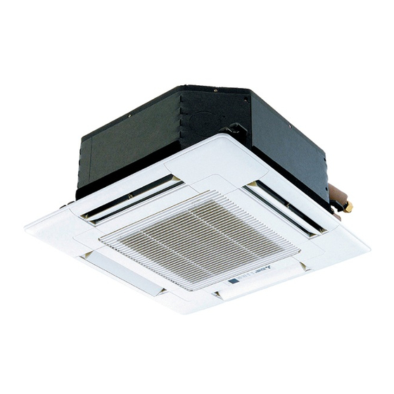
Indoor unit
[Model names]
SLZ-KA09NA
SLZ-KA12NA
SLZ-KA15NA
Model name
indication
INDOOR UNIT
REMOTE CONTROLLER
[Service Ref.]
SLZ-KA09NA.TH
SLZ-KA09NAR1.TH
SLZ-KA12NA.TH
SLZ-KA12NAR1.TH
SLZ-KA15NA.TH
SLZ-KA15NAR1.TH
TEMP.
ON/OFF
(Option)
CONTENTS
1. TECHNICAL CHANGES ...................... 2
2. PART NAMES AND FUNCTIONS ....... 2
3. SPECIFICATIONS ............................... 5
4. OUTLINES AND DIMENSIONS ........... 7
5. WIRING DIAGRAM .............................. 9
6. REFRIGERANT SYSTEM DIAGRAM ..... 10
7. TROUBLESHOOTING ....................... 11
8. SPECIAL FUNCTION ........................ 22
9. 4-WAY AIR FLOW SYSTEM .............. 23
10. DISASSEMBLY PROCEDURE ......... 25
PARTS CATALOG (OCB487)
9700058
December 2011
No. OCH487
REVISED EDITION-B
Revision:
• SLZ-KA09/12/15NAR1.TH
have been added in
REVISED EDITION-B.
• Some descriptions have
been modified.
• Please void OCH487
REVISED EDITION-A.
Note:
• This manual describes
only service data of the
indoor units.
• RoHS compliant products
have <G> mark on the
spec name plate.
• For servicing RoHS
compliant products, refer
to the RoHS Parts List.
Advertisement
Table of Contents

Related Manuals for Mitsubishi Electric SLZ-KA09NA


Summary of Contents for Mitsubishi Electric SLZ-KA09NA
-
Page 1: Table Of Contents
No. OCH487 REVISED EDITION-B TECHNICAL & SERVICE MANUAL Indoor unit Revision: [Model names] [Service Ref.] • SLZ-KA09/12/15NAR1.TH have been added in SLZ-KA09NA.TH REVISED EDITION-B. SLZ-KA09NA • Some descriptions have been modified. SLZ-KA09NAR1.TH • Please void OCH487 REVISED EDITION-A. SLZ-KA12NA.TH SLZ-KA12NA Note: •... -
Page 2: Technical Changes
Correct refrigerant is specifi ed in the manuals and on the spec labels provided with our products. We will not be held responsible for mechanical failure, system malfunction, unit breakdown or accidents caused by failure to follow the instructions. TECHNICAL CHANGES SLZ-KA09NA.TH SLZ-KA09NAR1.TH SLZ-KA12NA.TH SLZ-KA12NAR1.TH SLZ-KA15NA.TH... - Page 3 Radio frequency interface RF thermostat Wired remote controller TEMP. ON/OFF Wired remote controller (Option) Once the controllers are set, the same operation mode can be repeated by simply pressing the ON/OFF button. SLZ-KA09NA.TH SLZ-KA12NA.TH SLZ-KA15NA.TH SLZ-KA09NAR1.TH SLZ-KA12NAR1.TH SLZ-KA15NAR1.TH ON/OFF button...
- Page 4 Wired remote controller (Option) Display Section Day-of-Week “Sensor” indication For purposes of this explanation, Shows the current day of the week. Displays when the remote controller all parts of the display are shown. sensor is used. During actual operation, only the relevant items will be lit.
-
Page 5: Specifications
SPECIFICATIONS Indoor model SLZ-KA09NA SLZ-KA12NA SLZ-KA15NA Power supply V, phase, Hz 208/230, 1, 60 Max. fuse size (time delay)/Disconnect switch A Min. circuit ampacity Fan motor F.L.A 0.23 0.28 0.28 Airfl ow 280-320-350 280-320-390 280-320-390 (Low - Med. - High) -
Page 6: Noise Criterion Curves
NOISE CRITERION CURVES <60Hz> <60Hz> SLZ-KA12NA.TH SLZ-KA09NA.TH NOTCH SPL(dB) LINE NOTCH SPL(dB) LINE SLZ-KA12NAR1.TH SLZ-KA09NAR1.TH High High Medium Medium NC-70 NC-70 NC-60 NC-60 NC-50 NC-50 NC-40 NC-40 NC-30 NC-30 APPROXIMATE APPROXIMATE THRESHOLD OF THRESHOLD OF HEARING FOR HEARING FOR NC-20... -
Page 7: Outlines And Dimensions
OUTLINES AND DIMENSIONS SLZ-KA09NA.TH SLZ-KA12NA.TH SLZ-KA15NA.TH Unit : inch (mm) SLZ-KA09NAR1.TH SLZ-KA12NAR1.TH SLZ-KA15NAR1.TH Detail drawing of fresh air intake Fresh air intake 1(25) 3-15/16( 100) 2-7/8( 73.4) 3- 1/8( 2.8) 20-7/8(530) Cut out hole Burring hole Suspension bolt pitch 22-7/16(570) - Page 8 Unit : inch (mm) WIRED REMOTE CONTROLLER (Option) 5-1/8 (130) 3/4 (19) OCH487B...
-
Page 9: Wiring Diagram
WIRING DIAGRAM SLZ-KA09NA.TH SLZ-KA12NA.TH SLZ-KA15NA.TH SLZ-KA09NAR1.TH SLZ-KA12NAR1.TH SLZ-KA15NAR1.TH GRILLE OUTDOOR UNIT CNSK (RED) 1 3 5 7 9 (D·HEATER) (D·U·M) (POWER (POWER) (FAN) BOARD) DC13.1V CNDK (CONTROL) FUSE CN3C CN2S (WHT) X6 X5 X4 (POWER BOARD) CN2D LED3 LED2 LED1... -
Page 10: Refrigerant System Diagram
REFRIGERANT SYSTEM DIAGRAM SLZ-KA09NA.TH SLZ-KA12NA.TH SLZ-KA15NA.TH SLZ-KA09NAR1.TH SLZ-KA12NAR1.TH SLZ-KA15NAR1.TH Strainer Heat exchanger Refrigerant GAS pipe connection (Flare) Condenser/evaporator temperature thermistor (TH5) Refrigerant flow in cooling Refrigerant flow in heating Refrigerant LIQUID pipe connection (Flare) Pipe temperature thermistor/liquid Room temperature (TH2) -
Page 11: Troubleshooting
TROUBLESHOOTING 7-1. CAUTIONS ON TROUBLESHOOTING (1) Before troubleshooting, check the followings: 1 Check the power supply voltage. 2 Check that the indoor/outdoor connecting wire is correct. (2) Take care of the followings during servicing. 1 Before servicing the air conditioner, be sure to turn off the remote controller first to stop the main unit, and then turn off the breaker. - Page 12 • Refer to the following tables for details on the check codes. [Output pattern A] Beeper sounds Beep Beep Beep Beep Beep Beep Beep OPERATION · · · Repeated INDICATOR lamp blink pattern Approx. 2.5 sec. 0.5 sec. 0.5 sec. 0.5 sec.
- Page 13 • On IR wireless remote controller The continuous buzzer sounds from receiving section of indoor unit. Blink of operation lamp • On wired remote controller Check code displayed on the LCD. • If the unit cannot be operated properly after the test run, refer to the following table to find out the cause. Symptom Cause Wired remote controller...
- Page 14 Note: Refer to the manual of outdoor unit for the details of display 7-3. SELF-DIAGNOSIS ACTION TABLE such as F, U, and other E. Abnormal point and detection method Countermeasure Error Code Cause 1–3 Check resistance value of thermistor. Room temperature thermistor (TH1) 1 Defective thermistor 30°F ..
- Page 15 Abnormal point and detection method Countermeasure Error Code Cause Freezing/overheating protection is (Cooling or drying mode) (Cooling or drying mode) operating 1 Clogged filter (reduced airflow) 1 Check clogging of the filter. 1 Freezing protection (Cooling mode) 2 Short cycle of air path 2 Remove blockage.
- Page 16 Abnormal point and detection method Countermeasure Error Code Cause 1 Defective thermistor Pipe temperature thermistor / Condenser 1–3 Check resistance value of thermistor. / Evaporator (TH5) characteristics For characteristics, refer to (P1) above. 1 The unit is in 3-minute resume protection 2 Contact failure of connector 2 Check contact failure of connector (CN29) mode if short/open of thermistor is...
- Page 17 Abnormal point and detection method Countermeasure Error Code Cause 1 Contact failure, short circuit or, 1 Check disconnection or looseness of indoor/ Indoor/outdoor unit communication error (Signal receiving error) outdoor unit connecting wire of indoor unit or miswiring (converse wiring) of 1 Abnormal if indoor controller board indoor/outdoor unit connecting outdoor unit.
- Page 18 7-4. TEST POINT DIAGRAM 7-4-1. Indoor power board SLZ-KA09NA.TH SLZ-KA12NA.TH SLZ-KA15NA.TH SLZ-KA09NAR1.TH SLZ-KA12NAR1.TH SLZ-KA15NAR1.TH CN2S Connect to the indoor controller board (CN2D) between 1 to 3 12.6-13.7V DC (Pin1 (+)) CNSK Connect to the indoor controller board (CNDK) between 1 to 3 208/230V AC...
- Page 19 7-4-2. Indoor controller board SLZ-KA09NA.TH SLZ-KA12NA.TH SLZ-KA15NA.TH SLZ-KA09NAR1.TH SLZ-KA12NAR1.TH SLZ-KA15NAR1.TH LED3 LED2 CN2D LED1 Transmission Power supply Connector to the indoor power Power supply (Indoor/outdoor) (R.B) board (CN2S) (12.5~13.7V DC) (I.B) CN3C CN22 – Transmission Remote controller (Indoor/outdoor) connecting wire (0~24V DC) –...
- Page 20 7-5. TROUBLE CRITERION OF MAIN PARTS SLZ-KA09NA.TH SLZ-KA12NA.TH SLZ-KA15NA.TH SLZ-KA09NAR1.TH SLZ-KA12NAR1.TH SLZ-KA15NAR1.TH Part name Check method and criterion Room temperature Measure the resistance with a tester. thermistor (Part temperature 50°F ~ 86°F) (TH1) Normal Abnormal Pipe temperature 4.3k~9.6k Opened or short-circuited...
- Page 21 <Thermistor characteristic graph> < Thermistor for lower temperature > • Room temperature thermistor (TH1) Thermistor for • Pipe temperature thermistor/liquid (TH2) lower temperature • Condenser/evaporator temperature thermistor (TH5) Thermistor R =15k' ± 3% Fixed number of B=3480 ± 2% Rt=15exp { 3480( 273+(t-32)/1.8 30_F 15.8k'...
-
Page 22: Special Function
: Open) Jumper wire Setting by the dip switch and jumper wire Functions Remarks MODELS Setting 1 2 3 4 5 SLZ-KA09NA.TH Capacity 1 2 3 4 5 settings SLZ-KA12NA.TH 1 2 3 4 5 SLZ-KA15NA.TH <Initial setting> IR wireless remote controller: 0... -
Page 23: Way Air Flow System
Burring hole pitch 2-7/8 (Cut out hole) Ceiling surface Drain pipe Electrical Box Refrigerant pipe 9-2. FRESH AIR INTAKE AMOUNT & STATIC PRESSURE CHARACTERISTICS SLZ-KA09NA.TH SLZ-KA12NA.TH SLZ-KA15NA.TH SLZ-KA09NAR1.TH SLZ-KA12NAR1.TH SLZ-KA15NAR1.TH How to read curves Taking air into the unit Duct characteristics Q …... - Page 24 9-4. FIXING HORIZONTAL VANE Horizontal vane of each air outlet can be fixed according to the environment where it is installed. Setting procedure 1) Turn off a main power supply (Turn off a breaker). 2) Remove the vane motor connector in the direction of the arrow shown below with pressing the unlocking button as in the figure below.
-
Page 25: Disassembly Procedure
DISASSEMBLY PROCEDURE SLZ-KA09NA.TH SLZ-KA12NA.TH SLZ-KA15NA.TH SLZ-KA09NAR1.TH SLZ-KA12NAR1.TH SLZ-KA15NAR1.TH Be careful when removing heavy parts. OPERATING PROCEDURE PHOTOS & ILLUSTRATIONS 1. Removing the air intake grille Figure 1 (1) Slide the knob of air intake grille to the direction of the arrow 1 to open the air intake grille. - Page 26 OPERATING PROCEDURE PHOTOS & ILLUSTRATIONS 4. Removing the electrical parts Photo 3 Indoor power board (P.B) (1) Remove the 2 screws and the control box cover. <Electrical parts in the control box> • Indoor controller board (I.B) • Terminal block (TB4) •...
- Page 27 OPERATING PROCEDURE PHOTOS & ILLUSTRATIONS 8. Removing the fan motor (MF) Photo 6 Screw Flat plate (1) Remove the panel. (Refer to step 3) (2) Remove the drain pan. (Refer to step 6) Screws Fan motor (3) Remove the nut and the washer from the turbo fan, and (MF) remove the turbo fan.
- Page 28 Heat exchanger HEAD OFFICE : TOKYO BLDG., 2-7-3, MARUNOUCHI, CHIYODA-KU, TOKYO 100-8310, JAPAN CCopyright 2010 MITSUBISHI ELECTRIC CORPORATION Distributed in Dec. 2011 No.OCH487 REVISED EDITION-B New publication, effective Dec. 2011 Distributed in Jul. 2011 No.OCH487 REVISED EDITION-A Specifications are subject to change without notice.
Need help?
Do you have a question about the SLZ-KA09NA and is the answer not in the manual?
Questions and answers