
Related Manuals for Sony URX-S03D


Summary of Contents for Sony URX-S03D
- Page 1 4-590-341-11 (1) UHF Synthesized Diversity Tuner Operating Instructions URX-S03D © 2016 Sony Corporation...
-
Page 2: Table Of Contents
Table of Contents Features ............3 Parts Identification ........4 Preparation ..........5 Attaching to a Camcorder......5 Using Wireless Adapters ......5 Settings ............5 Setting the Receive Channel......5 Searching for Available Channels within a Group (Clear Channel Scan) ....6 Searching for Active Channels within a Group (Active Channel Scan) ...... -
Page 3: Features
The URX-S03D UHF Synthesized Diversity Tuner is a channel configurations quickly. two-channel slot-in wireless tuner that can be used in... -
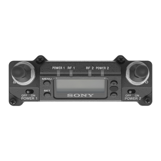
Page 4: Parts Identification
h SET button Parts Identification Changes the item to be set or enters the selected function or parameter value. i + or – button Use to select a function or value. j Infrared transmission port Transmits the frequency and compander mode settings configured on the unit to the transmitter. -
Page 5: Preparation
Setting the Receive Channel This receiver can be inserted into a slot provided on For details about the channel groups and channels that can compatible Sony camcorders. be selected, refer to the “Frequency List” on the CD-ROM. Remove the cover from the slot for the wireless... -
Page 6: Searching For Available Channels Within A Group (Clear Channel Scan)
Searching for Active Channels Notes within a Group (Active Channel • If there is no user input within 10 seconds after the channel group display or channel number display starts Scan) flashing, the displayed setting that is flashing is saved. The same applies when setting other parameters. -
Page 7: Using The Squelch Function
Be sure to lower the volume on all connected devices UWP-D: Select this when operating in conjunction before performing squelch function operations. If you with Sony UWP-D series transmitters. disable the squelch function while waiting for UWP: Select this when operating in conjunction with transmissions or receiving low-level RF inputs, for Sony UWP series transmitters. - Page 8 Use the + or – button to select “YES,” then press the Note SET button on the transmitter. This function cannot be used when operating in This sets the transmit channel and compander mode. conjunction with UWP or WRT series transmitters. Notes Searching for available channels and •...
-
Page 9: Menu Displays And Detailed Settings
ACT SCAN adapter. The function does not operate even when used SQUELCH with a compatible Sony slot-in type camcorder. To UTILITY menu Selecting output 1 (ANALOG OUT1) Select the output signal for when a camcorder with only one channel of analog input (e.g., HDCAM) is connected. -
Page 10: Rx (Tuner) 1/2 Menu
the signal to be used as the OUTPUT 1 connector’s sub Note output. When the receiver is turned off, the termination is Notes released. • OUTPUT 2 settings cannot be configured. Displaying the accumulated running time • Adjust the volume for each channel using the attenuator function on the transmitter. -
Page 11: Error Messages
Message Meaning Solution communication (AUTO SET)” (page 8). EEP ERROR An error has Contact your Sony occurred in the service representative. Selecting the frequency band (BAND) backup memory data. Select the receive frequency band. -
Page 12: Troubleshooting
Troubleshooting If you have any problem, use the following checklist before asking for repairs. If the problem persists, contact your Sony service representative. Symptom Cause Solution The unit does not turn The unit is not correctly inserted into the slot of the Insert the unit until it is firmly and completely in, camcorder or the wireless adapter. -
Page 13: Important Notes On Use
Important Notes on Use Specifications Antenna connector Usage and Storage BNC-R, 50 Ω (2) RF squelch level • Operating the UWP-D series devices near electrical 15 dBµ / OFF (0 dBµ = 1 µV) equipment (motors, transformers, or dimmers) may Audio output level cause interference due to electromagnetic induction. - Page 14 DURING THE WARRANTY PERIOD OR AFTER EXPIRATION OF THE WARRANTY, OR FOR ANY OTHER REASON WHATSOEVER. • SONY WILL NOT BE LIABLE FOR CLAIMS OF ANY KIND MADE BY USERS OF THIS UNIT OR MADE BY THIRD PARTIES. • SONY WILL NOT BE LIABLE FOR THE...
- Page 15 Sony Corporation...
Need help?
Do you have a question about the URX-S03D and is the answer not in the manual?
Questions and answers