
Related Manuals for Sony TA-FA777ES


Summary of Contents for Sony TA-FA777ES
-
Page 1: Service Manual
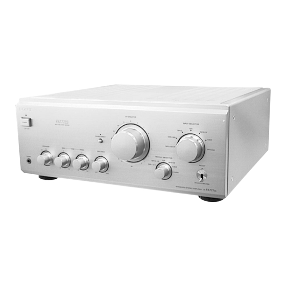
TA-FA777ES SERVICE MANUAL AEP Model SPECIFICATIONS INTEGRATED STEREO AMPLIFIER MICROFILM... -
Page 2: Table Of Contents
LINE WITH MARK 0 ON THE SCHEMATIC DIAGRAMS AND IN THE PARTS LIST ARE CRITICAL TO SAFE OPERATION. REPLACE THESE COMPONENTS WITH SONY PARTS WHOSE PART NUMBERS APPEAR AS SHOWN IN THIS MANUAL OR IN SUPPLEMENTS PUB- LISHED BY SONY. -
Page 3: General
SECTION 1 This section is extracted from instruction manual. GENERAL LOCATION OF CONTROLS... -
Page 4: Disassembly
SECTION 2 DISASSEMBLY Note: Follow the disassembly procedure in the numerical order given. FRONT PANEL, TOP board, BOTTOM board 1 four screws 1 four screws (FLAT HEAD) (FLAT HEAD) 2 top board 7 two screws (BV 3 × 8) 9 front panel qd bottom board qa two foots qs five screws... - Page 5 HEAT SINK (L) / (R) ASSY 2 two screws 3 heat sink (L) assy (4 × 8) 4 three connectors 5 heat sink (R) assy 2 two screws (CN501, 502, 503) (4 × 8) 6 three connectors (CN551, 552, 553) 1 two screws (4 ×...
-
Page 6: Electrical Adjustment
SECTION 3 ELECTRICAL ADJUSTMENT Note: Adjustment should be performed 5 minutes later, after the power switch is on. Bias Adjustment Setting: ATTENUATOR (Volume) control: minimum Input signal: No signal input Procedure: Adjust RT501 (L-CH) and RT551 (R-CH) for 70 mV reading on the VTVM. -
Page 7: Diagrams
SECTION 4 DIAGRAMS 4-1. NOTE FOR PRINTED WIRING BOARDS AND SCHEMATIC DIAGRAMS • Circuit Boards Location (In addition to this, the necessary note is printed in each block.) Note on Schematic Diagram: Note on Printed Wiring Boards: • All capacitors are in µF unless otherwise noted. pF: µµF •... -
Page 8: Printed Wiring Boards - Input/Main-B(L)/Main-B(R) Boards
TA-FA777ES (Page 10) (Page 12) (Page 10) 4-2. PRINTED WIRING BOARDS – INPUT/MAIN-B (L) /MAIN-B (R) Boards – • See page 7 for Circuit Boards Location. (Page 10) (Page (Page 10) (Page • Semiconductor Location – MAIN-B (L) Board –... -
Page 9: Schematic Diagram - Input(1/2)/Main-B(L)/Main-B(R) Boards
TA-FA777ES 4-3. SCHEMATIC DIAGRAM – INPUT (1/2) /MAIN-B (L) /MAIN-B (R) Boards – (Page 13) (Page 13) (Page 13) (Page 11) (Page 11) (Page 13) (Page 13) (Page 13) (Page 13) (Page 11) (Page 11) (Page 13) (Page 11) The components identified by mark 0 or dotted line with mark 0 are critical for safety. -
Page 10: Printed Wiring Boards - Balance/Function Sw/Sp Tm/Hp/Tone Control/Pro.led Boards
TA-FA777ES 4-4. PRINTED WIRING BOARDS – BALANCE/FUNCTION SW/SP TM/HP/TONE CONTROL/PRO.LED Boards – • See page 7 for Circuit Boards Location. (Page 8) • Semiconductor • Semiconductor Location Location – BALANCE Board – – FUNCTION SW Board – SP TM BOARD Ref. -
Page 11: Schematic Diagram - Balance/Function Sw/ Sp Tm/Input(2/2)/Hp/Tone Control(2/2)/ Pro.led Boards
TA-FA777ES 4-5. SCHEMATIC DIAGRAM – BALANCE/FUNCTION SW/SP TM/INPUT (2/2) /HP/TONE CONTROL (2/2) /PRO.LED Boards – (Page 9) (Page 13) (Page 13) (Page 13) (Page 9) (Page 9) (Page 9) (Page 9) (Page 13) (Page 13) • IC Block Diagram IC601 µPC1237HA... -
Page 12: Printed Wiring Boards - Main-A/Rv/Rec Out/Ps Pre/Ps/Outlet Boards
TA-FA777ES 4-6. PRINTED WIRING BOARDS – MAIN-A/RV/REC OUT/PS PRE/PS/OUTLET Boards – • See page 7 for Circuit Boards Location. PS PRE MAIN-A BOARD (Page 8) BOARD (Page 8) (Page 8) BOARD (Page 10) MAIN-A BOARD (Page 8) PS BOARD RV BOARD •... -
Page 13: Schematic Diagram - Main-A/Tone Control (1/2)/Rv/Rec Out/Ps Pre/Ps/Outlet Boards
TA-FA777ES 4-7. SCHEMATIC DIAGRAM – MAIN-A/TONE CONTROL (1/2)/RV/REC OUT/PS PRE/PS/OUTLET Boards – (Page 9) (Page 9) (Page 9) (Page 9) (Page 9) (Page 9) (Page 9) (Page 9) (Page 11) (Page 11) (Page 11) (Page 11) (Page 11) The components identified by mark 0 or dotted line with mark 0 are critical for safety. -
Page 14: Exploded Views
SECTION 5 EXPLODED VIEWS NOTE: (2) FRONT CHASSIS SECTION • -XX and -X mean standardized parts, so they • Items marked “*” are not stocked since they The components identified by mark 0 or dotted line with mark may have some difference from the original are seldom required for routine service. - Page 15 (3) MAIN CHASSIS SECTION C702 C701 103 102 supplied supplied supplied supplied supplied supplied supplied The components identified by mark 0 or dotted line with mark 0 are critical for safety. Replace only with part number specified. Ref. No. Part No. Description Remark Ref.
- Page 16 (4) BACK PANEL SECTION TM601 supplied TM602 supplied not supplied supplied The components identified by mark 0 or dotted not supplied line with mark 0 are critical for safety. Replace only with part number specified. Ref. No. Part No. Description Remark Ref.
-
Page 17: Electrical Parts List
2SC1815BL-TPE2 S901 1-762-920-11 SWITCH, ROTARY (INPUT SELECTOR) Q208 8-729-202-67 FET 2SK246GR3-TPE2 ************************************************************** Q209 8-729-018-60 TRANSISTOR 2SD2012-LC Q256 8-729-018-59 TRANSISTOR 2SB1375 (LB-SONY) 1-664-367-21 HP BOARD ********* Q257 8-729-201-53 TRANSISTOR 2SA1015TP-GR Q258 8-729-202-67 FET 2SK246GR3-TPE2 < CONNECTOR > Q259 8-729-018-59 TRANSISTOR 2SB1375 (LB-SONY) - Page 18 INPUT MAIN-A Ref. No. Part No. Description Remark Ref. No. Part No. Description Remark A-4392-509-A INPUT BOARD, COMPLETE R155 1-259-239-11 CARBON 1/4W ********************** R156 1-249-923-11 CARBON 1/4W 1-535-730-21 LEAD, JUMPER (OFC) R157 1-259-239-11 CARBON 1/4W 1-537-738-21 TERMINAL, EARTH R158 1-249-923-11 CARBON 1/4W R159 1-259-239-11 CARBON...
- Page 19 MAIN-A Ref. No. Part No. Description Remark Ref. No. Part No. Description Remark Q253 8-729-203-45 TRANSISTOR 2SC3423-Y C409 1-110-512-11 ELECT Q254 8-729-202-67 FET 2SK246GR3-TPE2 C410 1-125-845-21 FILM 47PF Q255 8-729-281-54 TRANSISTOR 2SC1815BL-TPE2 C411 1-119-830-11 ELECT 330uF C412 1-119-830-11 ELECT 330uF Q401 8-729-203-21 FET 2SK389-BL...
- Page 20 MAIN-A MAIN-B (L) MAIN-B (R) Ref. No. Part No. Description Remark Ref. No. Part No. Description Remark R263 1-259-151-21 CARBON 1/4W C517 1-137-163-11 FILM 0.33uF C520 1-119-835-31 ELECT 33uF R264 1-259-239-11 CARBON 1/4W C521 1-162-286-31 CERAMIC 220PF R265 1-249-844-11 CARBON 1/2W C522 1-119-834-11 ELECT...
- Page 21 MAIN-B (R) OUTLET PRO.LED Ref. No. Part No. Description Remark Ref. No. Part No. Description Remark C571 1-162-286-31 CERAMIC 220PF CN52 1-580-629-11 PIN, CONNECTOR 2P C572 1-119-834-11 ELECT 22uF * CN53 1-564-321-21 PIN, CONNECTOR 2P < CONNECTOR > < FUSE > * CN551 1-564-506-11 PLUG, CONNECTOR 3P 0 F51...
- Page 22 PS PRE REC OUT SP TM Ref. No. Part No. Description Remark Ref. No. Part No. Description Remark R703 1-249-576-11 CARBON 1/4W < SWITCH > ************************************************************** A-4426-971-A PS PRE BOARD, COMPLETE S302 1-762-186-11 SWITCH, TOGGLE (RECOUT) *********************** ************************************************************** 2-259-121-01 SCREW, TR 1-664-365-21 RV BOARD 4-880-403-11 HEAT SINK *********...
-
Page 23: Tone Control
SP TM TONE CONTROL Ref. No. Part No. Description Remark Ref. No. Part No. Description Remark * EPT606 4-843-416-11 PLATE, FIXED, CAP A-4426-973-A TONE CONTROL BOARD, COMPLETE * EPT607 4-843-416-11 PLATE, FIXED, CAP ***************************** * EPT608 4-843-416-11 PLATE, FIXED, CAP <... - Page 24 TA-FA777ES TONE CONTROL Ref. No. Part No. Description Remark Ref. No. Part No. Description Remark S801 1-762-184-11 SWITCH, ROTARY (SPEAKERS) ************************************************************** MISCELLANEOUS ************** 1-506-113-00 SHORT PLUG * 162 1-535-691-31 TERMINAL 0 170 1-580-375-41 INLET 3P C701 1-131-864-11 CAP, ELECT C702...
Need help?
Do you have a question about the TA-FA777ES and is the answer not in the manual?
Questions and answers