Philips DVP642/37 Service Manual
Hide thumbs
Also See for DVP642/37:
- User manual (39 pages) ,
- Manual (7 pages) ,
- Quick use manual (2 pages)
Table of Contents
Advertisement
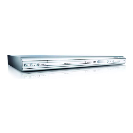
DVD Player
Service
Service
Service
Service
Service
Service Manual
This service manual is for DVP642/37 Second
Generation model, which is different from the
previous generation DVP642/37 model.
For Second Generation model, the serial number
should begin with KN03xxxxxxxxxx.
Refer to the rating label illustration on the right.
©
Copyright 2006 Philips Consumer Electronics B.V. Eindhoven, The Netherlands
All rights reserved. No part of this publication may be reproduced, stored in a retrieval system or
transmitted, in any form or by any means, electronic, mechanical, photocopying, or otherwise
without the prior permission of Philips.
Published by HY-ET0622 Service Audio Printed in The Netherlands
Version 1.0
Subject to modification
DVP642/
Second Generation
GB
3139 785 32180
37
Advertisement
Table of Contents

Related Manuals for Philips DVP642/37


Summary of Contents for Philips DVP642/37
- Page 1 Refer to the rating label illustration on the right. © Copyright 2006 Philips Consumer Electronics B.V. Eindhoven, The Netherlands All rights reserved. No part of this publication may be reproduced, stored in a retrieval system or transmitted, in any form or by any means, electronic, mechanical, photocopying, or otherwise without the prior permission of Philips.
-
Page 2: Location Of Pc Boards
LOCATION OF PC BOARDS LED PCB MAIN PCB POWER PCB CONTROL PCB VERSION VARIATION: Type/Versions DVP642 Features & Board in used DivX 6.0 function P-scan (SW control) RGB Out Power PCB (120V/60Hz) -
Page 3: Specifications
SPECIFICATIONS AUDIO PERFORMANCE TV STANDARD (PAL/50Hz) (NTSC/60Hz) 24 bit Number of lines DA Converter fs 96 kHz 4Hz- 44kHz Playback Multistandard (PAL/NTSC) fs 48 kHz 4Hz- 22kHz SVCD fs 48 kHz 4Hz- 22kHz VIDEO PERFORMANCE fs 44.1kHz 4Hz- 20kHz CD/VCD fs 44.1kHz 4Hz- 20kHz CVBS... -
Page 4: Aux Section
Measurement Setup AC MILLIVOL TME TER LOAD 4 OHM AUTO DISTORTION METER AC MILLIVOL TME TER LOAD 4 OHM AUTO DISTORTION METER OSCIL LOSCOPE OSCIL LOSCOPE ..........INPUT INPUT ......R L C SRSLSW R L C SRSLSW SIGNAL GENERATORAC DVD TEST DISC... -
Page 5: Service Aids
SERVICE AIDS Service Tools: Universal Torx driver holder .........4822 395 91019 Torx bit T10 150mm ...........4822 395 50456 Torx driver set T6-T20 .........4822 395 50145 Torx driver T10 extended ........4822 395 50423 Compact Disc: SBC426/426A Test disc 5 + 5A ......4822 397 30096 SBC442 Audio Burn-in test disc 1kHz ....4822 397 30155 SBC429 Audio Signals disc .........4822 397 30184 Dolby Pro-logic Test Disc ........4822 395 10216... -
Page 6: Class 1 Laser Product
WAARSCHUWING WARNING Alle IC’s en vele andere halfgeleiders zijn All ICs and many other semi-conductors are gevoelig voor electrostatische ontladingen susceptible to electrostatic discharges (ESD). (ESD). Careless handling during repair can reduce life Onzorgvuldig behandelen tijdens reparatie kan drastically. de levensduur drastisch doen verminderen. When repairing, make sure that you are Zorg ervoor dat u tijdens reparatie via een connected with the same potential as the mass... - Page 7 You will find this and more technical information • Use only lead-free solder alloy Philips SAC305 with within the “magazine”, chapter “workshop news”. order code 0622 149 00106. If lead-free solder-paste is required, please contact the manufacturer of your For additional questions please contact your local solder-equipment.
- Page 8 Select the menu using the " " and " " button on R/C After replacement / repair of the MPEG board, the customer c) Go picture setup page select Video out item. For DVP642/37 (US) : setting and the region code may lost. Changing the Region <789> <OK> <01> <PLAY>...
-
Page 9: Repair Instructions
REPAIR INSTRUCTIONS MAIN UNIT REPAIR CHART 1/2 POWER SUPPLY AUDIO LINE DIGITAL LINE ALL FUNCTION VFD DISPLAY NO SHOW DVD NO NO WORKING NO OUTPUT NO OUTPUT NO WORKING ANY KEY FUNCTION VIDEO VFD display no show All function any key fuction no working Check all system Re-insert and... - Page 10 REPAIR INSTRUCTIONS MAIN UNIT REPAIR CHART 2/2 Audio line Digital line No output No output No video Check JK100 Change JK100 Check JK201 is good Change JK201 is good Change Check JK102 JK102 good At DVD mode Check 5V Check between Repair between check Q116 C=5V supply circuit...
-
Page 11: Disassembly Instructions
DISASSEMBLY INSTRUCTIONS Dismantling of the Key Board Assembly Dismantling of the MAIN Board 1) Open the DVD Tray by using the Open/Close Button 2) Return the set to its upright position and remove the Tray 1) Loosen 4 screws A at the back panel as shown in figure 4. while the Set is ON and disconnect the mains supply after Cover as shown in Figure 3 and close the tray manually 1) Loosen 2 screws B at the Main Board as shown in figure 5. -
Page 12: Service Positions
SERVICE POSITIONS Dismantling of the POWER BOARD 1) Loosen 3 screws D at the power board as shown in figure 7. 2) Remove 2 catchs from power board as shown in figure 8. Service position A Figure 7 Note: In some service positions the components or copper patterns of one board may risk touching its neighbouring pc boards or metallic parts. -
Page 13: Block Diagram
BLOCK DIAGRAM... -
Page 14: Wiring Diagram
WIRING DIAGRAM... -
Page 15: Ftd Display Pin Assignment
FTD DISPLAY PIN ASSIGNMENT CONTROL / LED BOARD ( 1G - 7G ) j, p j, p j, p j, p j, p j, p j, p TABLE OF CONTENTS FTD Display Pin Assignment & Pin Voltage ....5-1 Circuit Diagram ..............5-2 PCB Layout Top View ............ - Page 16 CIRCUIT DIAGRAM - CONTROL & LED BOARD C2501 C2507 C2513 C2519 D2507 R2501 R2509 R2515 R2521 R2528 R2535 R2541 TA2504 C2502 C2508 C2514 C2520 DP251 R2502 R2510 R2516 R2522 R2529 R2536 RB2502 B4 XL2501 C2503 C2509 C2515 CN104B B1 IC2500 R2504 R2511 R2517...
- Page 17 PCB LAYOUT TOP VIEW - CONTROL & LED BOARD C2503 C2505 C2516 CN104B A2 LD2500 A1 RB2502 A1 TA2500 TA2502 XL2501 C2504 C2513 C2520 DP251 R2502 SN251 TA2501 TA2504 PCB LAYOUT BOTTOM VIEW - CONTROL & LED BOARD C2501 C2509 C2515 D2503 Q2502...
-
Page 18: Main Board
EN29LV800BB INTERNAL IC DIAGRAM WRITE CONTROL PROGRAM/ERASE STATE INPUT HIGH VOLTAGE MACHINE LOGIC RESET# (WSM) STATE MAIN BOARD REGISTER MX29LV800BT/BB ADDRESS FLASH LATCH ARRAY ARRAY A0-A18 SOURCE COMMAND DATA BUFFER Y-PASS GATE DECODER SENSE DATA COMMAND AMPLIFIER DATA LATCH TABLE OF CONTENTS PROGRAM DATA LATCH Internal IC Diagram ............ - Page 19 CIRCUIT DIAGRAM -MAIN BOARD (TOP LEFT) C100 B1 C108 D1 C117 A6 C125 A6 C134 A5 C142 A3 C152 C1 C163 A4 C172 A3 C180 C6 C189 B5 C197 B4 C207 D4 C216 C5 C228 D5 C236 C5 C252 C5 C260 D6 C268 D2 D102 B6...
- Page 20 CIRCUIT DIAGRAM -MAIN BOARD (TOP RIGHT) L114 L125 D6 Q104 A5 Q112 C6 R107 D1 R116 A4 R125 B6 R136 B1 R154 D1 R163 D3 R173 B6 R184 A6 R194 D3 R203 C4 R211 D5 R220 D5 R228 D5 R237 B6 R246 D2 R255 A3 R265 A3...
- Page 21 CIRCUIT DIAGRAM - MAIN BOARD (BOTTOM LEFT)
- Page 22 CIRCUIT DIAGRAM - MAIN BOARD (BOTTOM RIGHT) C271 01UF/50V L103 R0603-1K L101 L102...
- Page 23 PCB LAYOUT - MAIN BOARD (TOP VIEW) C102 C177 C209 C222 C264 FB123 L124 Q106 R120 R153 R190 R218 U103 C103 C178 C210 C223 C265 FB124 L125 Q107 R123 R159 R195 R219 U104 C104 C179 C211 C227 CN100 JK100 L129 Q108 R124 R168...
- Page 24 PCB LAYOUT - MAIN BOARD (BOTTOM VIEW) C106 C138 C110 L116 C228 R209 C129 C119 C137 L117 C238 R233 R116 C182 U100 R113 C257 R264 C128 C156 C121 L118 C230 R210 C132 C120 C145 Q112 C240 R234 R145 C193 C100 R114 C258 R265...
- Page 25 VOLTAGE U104(MX29LV800CBTC) IC100(AZ809NSTR-E1) Pin NO Pin NO Voltage 0.00 3.3. 3.30 Voltage 0.00 2.33 0.09 1.73 2.59 1.03 1.72 2.08 3.29 3.30 3.30 3.27 3.30 3.30 1.31 0.00 0.08 0.39 1.87 1.67 Pin NO U100(TU24C02CS2BF) Voltage 1.30 1.66 1.65 1.67 1.66 0.00 0.00 0.00...
-
Page 26: Power Board
Voltage Pin NO Voltage Pin NO Voltage POWER BOARD Pin NO Voltage Pin NO Voltage Pin NO Voltage 0.00 TABLE OF CONTENTS Pin NO Voltage ................8-1 Voltage 0.00 Circuit Diagram ..............8-2 PCB Layout Top & Bottom View ........8-3... - Page 27 CIRCUIT DIAGRAM - POWER BOARD C903 C909 C923 CN903 D905 D910 IC902 J904 J909 L908 R903 R909 R922 R927 C904 C918 C927 D901 D906 D911 IC903 J905 L901 Q901 R905 R910 R923 R928 C905 C919 C929 D902 D907 D912 J901 J906 L902 Q902...
- Page 28 PCB LAYOUT - POWER BOARD C903 C909 C923 CN903 D905 D910 IC902 J904 J909 L908 R903 R909 R922 R927 C904 C918 C927 D901 D906 D911 IC903 J905 L901 Q901 R905 R910 R923 R928 C905 C919 C929 D902 D907 D912 J901 J906 L902 Q902...
- Page 29 EXPLODED DRAWING- MAIN UNIT...
- Page 30 MAIN ENCASING & ACCESSORIES PARTS LIST DVP642/37 KN03XXXXXXXXXX=BOM 2 9965 000 38596 DVD LOADER ASS‘Y M04S-5 ASL261603-1112 9965 000 38597 MAIN PCB ASS’Y LEAD FREE APE106460-0001 9965 000 38598 $ POWER PCB ASS’Y APE303790-0004 9965 000 38599 CONTROL LED PCB ASS’Y...
Need help?
Do you have a question about the DVP642/37 and is the answer not in the manual?
Questions and answers