Acer TRAVELMATE 8172 Service Manual
Acer laptop user manual
Hide thumbs
Also See for TRAVELMATE 8172:
- User manual (62 pages) ,
- Quick manual (314 pages) ,
- Service manual (107 pages)

Related Manuals for Acer TRAVELMATE 8172


Summary of Contents for Acer TRAVELMATE 8172
- Page 1 TravelMate 8172/8172Z Series Service Guide Service guide files and updates are available on the ACER/CSD web; for more information, please refer to http://csd.acer.com.tw PRINTED IN TAIWAN...
-
Page 2: Revision History
Revision History Please refer to the table below for the updates made on TravelMate 8172/8172Z service guide. Date Chapter Updates... - Page 3 Copyright Copyright © 2010 by Acer Incorporated. All rights reserved. No part of this publication may be reproduced, transmitted, transcribed, stored in a retrieval system, or translated into any language or computer language, in any form or by any means, electronic, mechanical, magnetic, optical, chemical, manual or otherwise, without the prior written permission of Acer Incorporated.
- Page 4 Conventions The following conventions are used in this manual: SCREEN MESSAGES NOTE WARNING CAUTION IMPORTANT Denotes actual messages that appear on screen. Gives bits and pieces of additional information related to the current topic. Alerts you to any damage that might result from doing or not doing specific actions.
- Page 5 DIFFERENT part number code to those given in the FRU list of this printed Service Guide. You MUST use the list provided by your regional Acer office to order FRU parts for repair and service of customer machines.
-
Page 7: Table Of Contents
Acer eRecovery Management ........21... - Page 8 TravelMate 8172/8172Z FRU List ........
-
Page 9: System Specifications
System Specifications Features Below is a brief summary of the computer’s many features: Operating system ® Genuine Windows 7 Professional 32-bit ® Genuine Windows 7 Home Premium 64-bit CPU and chipset ® Intel Core™ i5-430UM/i5-520UM/i5-540UM processor (3 MB L3 cache, 1.20/1.06/1.20 GHz with Turbo Boost up to 1.73/1.86/2 GHz, DDR3 800 MHz, 18 W), supporting Intel Cache ®... -
Page 10: Dimensions And Weight
Built-in microphone Webcam Acer Video Conference, featuring: Acer Crystal Eye webcam with 1280 x 1024 resolution Acer Video Conference Manager software, featuring Video Quality Enhancement (VQE) technology, supporting 640 x 480 resolution online video calls Wireless and networking WLAN: Acer InviLink™ Nplify™ 802.11b/g/n Wi-Fi CERTIFIED™... -
Page 11: Input And Output
External display (VGA) port Headphone/speaker/line-out jack Microphone-in jack Ethernet (RJ-45) port DC-in jack for AC adapter Security Acer Bio-Protection fingerprint solution, featuring Pre-Boot Authentication (PBA), computer protection, Acer FingerLaunch BIOS user, supervisor, HDD passwords Kensington lock slot Software Productivity Acer ePower Management Acer eRecovery Management ®... -
Page 12: Options And Accessories
Web links and utilities Acer Accessory Store (Belgium, France, Germany, Italy, Netherlands, Spain, Sweden, UK only) Acer Identity Card Acer Registration Acer Updater ® eBay shortcut 2009 (Canada, France, Germany, Italy, Mexico, Spain, UK, US only) Netflix shortcut (US only) -
Page 13: System Block Diagram
System Block Diagram Chapter 1... -
Page 14: Board Layout
Board Layout Top View TravelMate 8172/8172Z M/B layout and connector location Name CN10 CN11 CN31 8 11 TOP view Description LCM connector Power Keyboard connector Microphone connector Touch pad connector Audio cable connector 1 Audio cable connector 2 Card reader slot... -
Page 15: Bottom View
Bottom View TravelMate 8172/8172Z M/B layout and connector location Name CN12 CN13 CN14 CN15 CN16 CN17 CN18 CN18 CN20 CN21 CN22 CN23 CN24 CN25 CN26 Chapter 1 Bottom view LAN slot Battery connector DC-in jack EZ-Docking slot SIM Card slot... - Page 16 TravelMate 8172/8172Z M/B layout and connector location Name CN27 Bottom view Earphone connector South bridge CPU+ North bridge Description Chapter 1...
-
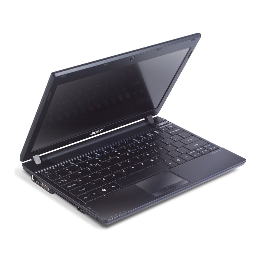
Page 17: Your Acer Notebook Tour
For entering data into your computer. Touch-sensitive pointing device which functions like a computer mouse. The center button serves as the Acer Bio-Protection fingerprint reader, supporting Pre-Boot Authentication (PBA) computer protection, Acer FingerLaunch. The left and right buttons function like the left and right mouse buttons. -
Page 18: Closed Front View
Icon Power switch Acer Crystal Eye webcam Closed Front View Icon Power indicator Battery indicator Communication indicator HDD indicator Rear view Icon Battery Item Turns the computer on and off. Web camera for video communication. Item Indicates the computer's power status. -
Page 19: Left View
Insert the lock into the notch and turn the key to secure the lock. Some keyless models are also available. network. Connects to Acer EasyPort. Enable the computer to stay cool,even after prolonged use. Connect to USB 2.0 devices (e.g., USB mouse, USB camera). -
Page 20: Base View
USB 2.0 port External display (VGA) port DC-in jack Base view Icon Battery bay Battery lock Hard disk bay Acer DASP (Disk Anti-Shock Protection) Memory compartment Battery release latch Environment Item Connects to USB 2.0 devices (e.g., USB mouse, USB camera). -
Page 21: Touchpad Basics (With Fingerprint Reader)
Touchpad Basics (with fingerprint reader) The following items show you how to use the touchpad with Acer Bio-Protection fingerprint reader. Move your finger across the touchpad (1) to move the cursor. Press the left (2) and right (4) buttons located beneath the touchpad to perform selection and execution functions. -
Page 22: Touchpad Basics (With Two-Click Buttons)
Touchpad basics (with two-click buttons) The following items show you how to use the touchpad with two-click buttons. Move your finger across the touchpad to move the cursor. Press the left and right buttons located beneath the touchpad to perform selection and execution functions. -
Page 23: Using The Keyboard
Using the Keyboard The keyboard has full-sized keys and an embedded numeric keypad*, separate cursor, lock, Windows, function and special keys. Lock Keys and embedded numeric keypad* The keyboard has three lock keys which you can toggle on and off. Caps Lock Lock key Caps Lock... -
Page 24: Windows Keys
Windows Keys The keyboard has two keys that perform Windows-specific functions. Windows Pressed alone, this key has the same effect as clicking on the Windows Start button; it launches the Start menu. It can also be used with other keys to provide a variety of functions: <... -
Page 25: Hot Keys
Hot Keys The computer employs hotkeys or key combinations to access most of the computer's controls like screen brightness and volume output. To activate hot keys, press and hold the <Fn> key before pressing the other key in the hotkey combination. Hotkey Icon <Fn>... -
Page 26: Using The System Utilities
* Acer ProfileLaunch, MusicLaunch, MyLaunch and FingerNav are only available on select models. ** In models without Acer ProfileLaunch, Acer FingerLaunch can be used to open applications in the Acer ProfileLaunch icons area; a single finger swipe will launch only one application at a time. - Page 27 Acer GridVista is a handy utility that offers four pre-defined display settings so you can view multiple windows on the same screen. To access this function, please go to Start, All Programs and click on Acer GridVista. You may choose any one of the four display settings indicated below: Double (vertical), Triple (primary at left), Triple (primary at right), or Quad.
-
Page 28: Acer Backup Manager
Once you have finished these three steps, backups will be created according to the schedule. You can also create backups manually by pressing the Acer Backup Manager key. If you wish to change your settings at any time, run Acer Backup Manager from the Start menu and go through the steps outlined above. -
Page 29: Power Management
When you press the Acer PowerSmart key, the screen brightness is reduced and the graphics chip switched to a lower speed; PCI and WLAN switch to power-saving modes. Press the Acer PowerSmart key again to return to your previous settings. -
Page 30: Burn Backup Discs
Burn backup discs From the Backup page of Acer eRecovery Management, you can burn the factory default image or back up drivers and applications. 1. Click on Start > All Programs > Acer > Acer eRecovery Management. 2. Acer eRecovery Management opens to the Backup page. -
Page 31: Restore Windows Vista From Backup Discs
1. Turn on your computer and insert the first system recovery disc into the optical disc drive. Restart your computer. 2. During startup when the Acer logo shows, press the F2 key to enter BIOS Setup, where you can set system parameters. -
Page 32: Hardware Specifications And Configurations
Hardware Specifications and Configurations Processor Item Type Description L3 Cache TDP (Thermal) Socket type Second Level Cache Item North Bridge South Bridge System Memory Item Technology Base memory Expansion memory Maximum memory size Lan Interface Item Controller (AVAP) SPEED Wireless LAN Item Module Interface... - Page 33 Bluetooth Interface Item Module Antenna controller Bluetooth module Hard Disk Drive Interface Item HDD form factor Media I/F IDE Controller Audio Interface Item Sound Codec (AVAP) Internal Speakers Internal Microphone Sound Volume LCD panel Item Vendor and model name Screen Diagonal [mm] Active Area [mm] Pixels H x V Pixel Pitch [mm]...
- Page 34 Item Physical Size Include bracket [mm] Electrical Interface Glass Thickness [mm] Surface Treatment Support Color Temperature Range Operating[ Storage (Non-Operating)[ RoHS Compliance Viewing Angle [degree] Brightness Card Slot Item 5 in 1 card reader (SD/MMC/MS/ MSPro/xD) WebCAM Item Module Interface Min.
- Page 35 BIOS Power Management Item Controller Interface AC adapter (AVAP) 1st Battery (AVAP) Chapter 1 Specification Acer NT1T Specification Full mini card (3G) x 1 & Half mini card (SP WLAN) x 1 Specification 1 (mechanical, Blue) None None None None...
- Page 36 LED Status Indicator Item Power Status 1st Battery Status Caps Lock Num Lock Wireless LAN Bluetooth Security Features Item Kensington Lock Hole(7.5 mm diameter) Fingerprint Item Not Noise Number Physical Characteristics Item Dimensions Thickness (maximum) Weight (incl 1st Battery & super multi ODD) Specification 1 (Blue / Orange)
-
Page 37: Bios Setup Utility
System Utilities BIOS Setup Utility The BIOS Setup Utility is a hardware configuration program built into your computer’s BIOS (Basic Input / Output System). Your computer is already properly configured and optimized, and you do not need to run this utility. However, if you encounter configuration problems, you may need to run Setup.Please also refer to Chapter 4 Troubleshooting when problem arises. -
Page 38: Invoking Bios Setup
Invoking BIOS Setup The setup function can only be invoked by pressing F2 when Press <F2> to enter Setup message is prompted on the bottom of screen during POST. The setup uses a menu driven interface to allow the user to configure their system. The features are divided into 5 parts as follows: Information Display the system informations. -
Page 39: Main
Parameter IDE0 Serial Number ATAPI Model Name System BIOS version VGA BIOS Version Serial Number Asset Tag Number Product Name UUID Number Main The Main screen displays a summary of your computer hardware information, and also includes basic setup parameters. It allows the user to specify standard IBM PC AT system parameters. Information System Time: System Date:... - Page 40 NOTE: The sub-items under each device will not be shown if the device control is set to disable or auto. This is because the user is not allowed to control the settings in these cases. NOTE: Please refer to Acer’s VGA TAG table.For Intel switchable graphic platforms, Video memory refers to the dedicated VRAM size of discrete graphics.
-
Page 41: Security
Security The Security screen contains parameters that help safeguard and protect your computer from unauthorized use. Information. Supervisor Password Is User Password Is HDD Password Set Supervisor Password Set User Password Set HDD Password Password on Boot: Help ↑↓ ←→ Exit Chapter 2 InsydeH2O Setup Utility... -
Page 42: Set Supervisor Password
The table below describes the parameters in this screen. Settings in boldface are the default and suggested parameter settings. Parameter Supervisor Password User Password is HDD Password is Set Supervisor Password Set User Password Set Hdd Passwor Password on Boot NOTE: When you are prompted to enter a password, you have three tries before the system halts. - Page 43 User can now type password in field “ Enter New Password“, and re-enter password in field “Confirm New Password“ for verification. Enter current password Enter New Password Confirm New Password If the verification is OK: The password setting is complete after user presses enter. If the new password and confirm new password strings do not match: The format of the password is as follows: Password Max Length : 8 characters.
-
Page 44: Boot
Boot This menu allows the user to decide the order of boot devices to load the operating system. Bootable devices includes the distette drive in module bay, the onboard hard disk drive and the CD-ROM in module bay. Information Boot priority order: 1. -
Page 45: Exit Saving Changes
The table below describes the parameters in this screen. Parameter Exit Saving Changes Exit Discarding Changes Load Setup Default Discard Changes Save Changes Exit Saving Changes Allows the user to save changes and reboot the system. The following message is shown when user presses System will reboot if Yes is selected and will stay in Setup if No is selected.. -
Page 46: Discard Changes
Discard Changes Allows the user to discard previous changes in Setup. The following message is shown when user presses Save Changes Allows the user to save current changes in Setup. The following message is shown when user presses “ ” Enter on this item: Setup Confirmation... -
Page 47: Bios Flash Utility
BIOS Flash Utility The BIOS flash memory update is required for the following conditions: New versions of system programs New features or options Restore a BIOS when it becomes corrupted. Use the Phlash utility to update the system BIOS flash ROM. NOTE: If you do not have a crisis recovery diskette at hand, then you should create a Crisis Recovery Diskette before you use the Phlash utility. -
Page 48: Dos Flash Bios Sop
DOS flash BIOS SOP 1. Please prepare a bootable flash disk. 2. Unzip the “BIOS” and leave the DOS file in the bootable flash disk. Chapter 2... - Page 49 3. Insert the flash disk with the unzip file. 4. Connect the adapter. Chapter 2...
- Page 50 5. Log in the DOS by bootable flash disk and type the name of “exe file”and press Enter. The system will flash BIOS automatically. NOTE: The version of BIOS must be newer than original version. NOTE: Adapter have to be connected. Chapter 2...
-
Page 51: Clean Bios Password Sop
Clean BIOS Password SOP 1. Please prepare a bootable flash disk. 2. Unzip the “CleanBIOSPassword” and leave it in the bootable flash disk. Chapter 2... - Page 52 3. Insert the flash disk with the unzip file. 4. Connect the adapter. Chapter 2...
- Page 53 5. Set the supervisor BIOS and enable Power on Password. 6. Please insert bootable USB device, and press “alt gr+backspace+Esc” and press power button. Chapter 2...
- Page 54 7. The system will automatically ignore the power on password and log in the bootable flash disk. 8. Insert “clearbpw” . Chapter 2...
- Page 55 9. When the screen show “Clear the SU PWs completely” means the BIOS password removed completely. Chapter 2...
-
Page 56: Clean Hdd Password Sop
Clean HDD Password SOP 1. Please prepare a bootable flash disk. 2. Unzip the “CleanHDDPassword” and leave it in the bootable flash disk. Chapter 2... - Page 57 3. Insert the flash disk with the unzip file. 4. Connect the adapter. Chapter 2...
- Page 58 5. After inserting the wrong HDD password three times. The system will show select item screen. 6. Memorize the error code behind the “Enter Unlock Password” . NOTE: the number will be created by system in disorder. Chapter 2...
- Page 59 7. Remove the disk and insert it in other system. 8. Log in DOS mode in other system. Execute the “Unlockhd” in the bootable flash disk by insert the keyword: “unlockhd+ space + error code” . Chapter 2...
- Page 60 9. The program will create a password. Please memorize it. 10. Remove the bootable flash disk and re-install in the original system. Chapter 2...
- Page 61 11. Enter the password and the HDD lock will be released. Chapter 2...
-
Page 62: Crisis Disk Sop
Crisis Disk SOP 1. Please prepare a bootable flash disk. 2. Unzip the “Crisis disk” and leave it in the bootable flash disk. Chapter 2... - Page 63 3. Insert the flash disk with the unzip file. 4. Connect the adapter. Chapter 2...
- Page 64 5. Press “Fn+ESC+Power” to power on the system. 6. The system will automatically power on after several minutes. 7. Please use normal BIOS flash procedure to flash BIOS again when the machine be rescued. Chapter 2...
-
Page 65: Dmi Utility Sop
DMI Utility SOP 1. Please prepare a bootable flash disk. 2. Unzip the “dmi174” and leave it in the bootable flash disk. Chapter 2... - Page 66 3. Insert the flash disk with the unzip file. 4. Connect the adapter. Chapter 2...
- Page 67 5. Log in dos mode and type “dmi174r” to execute the program. 6. Activate the program. Chapter 2...
- Page 68 7. Type “DMI174 /?” can check all of the function of DMI. Chapter 2...
-
Page 69: Lan Eeprom Utility Sop
LAN EEPROM Utility SOP 1. Please prepare a bootable flash disk. 2. Unzip the MAC.zip and leave it in the bootable flash disk. Chapter 2... - Page 70 3. Insert the flash disk with the unzip file. 4. Connect the adapter. Chapter 2...
- Page 71 5. Power on the system and press F2 to log in the BIOS. Select the USB HDD to the first priority. 6. Save the BIOS setting, the system will reboot automatically and log in DOS. Chapter 2...
- Page 72 7. Go in to the file of MAC. Insert the “ßmacin.bat” . 8. Input the MAC address. Chapter 2...
-
Page 73: Winflash Sop
Winflash SOP 1. Please prepare a bootable flash disk. 2. Unzip the file and leave it in the flash disk. Chapter 2... - Page 74 3. Insert the flash disk with the unzip file. 4. Connect the adapter. Chapter 2...
- Page 75 5. Double click the Winflash tool and begin to flash BIOS. NOTE: The version of BIOS must be newer than original version. NOTE: Adapter have to be connected. Chapter 2...
- Page 76 Chapter 2...
-
Page 77: Disassembly Requirements
Machine Disassembly and Replacement Disassembly Requirements To disassemble the computer, you need the following tools: Wrist grounding strap and conductive mat for preventing electrostatic discharge Flat screwdriver Philips screwdriver Plastic flat screwdriver Plastic tweezers NOTE: The screws for the different components vary in size. During the disassembly process, group the screws with the corresponding components to avoid mismatch when putting back the components Related Information The product previews seen in the disassembly procedures may not represent the final product color or... -
Page 78: Pre-Disassembly Instructions
Pre-disassembly Instructions Before proceeding with the disassembly procedure, make sure that you do the following: 1. Turn off the power to the system and all peripherals. 2. Unplug the AC adapter and all power and signal cables from the system. 3. -
Page 79: Disassemble Process
M2*2.5 External Module Disassembly Process NOTE: The product previews seen in the disassembly procedures may not represent the final product color or configuration. Screw List Step Wireless Module Disassembly Chapter 3 Quantity Screw Quantity M2.5*4L Acer part no part no... -
Page 80: Removing The Battery Pack
Removing the Battery Pack 1. Turn the computer over. 2. Slide the battery lock/unlock latch to the unlock position. Chapter 3... - Page 81 3. Slide and hold the battery to the release position (1) and remove the battery from the main unit (2). Chapter 3...
-
Page 82: Removing The Hdd
Removing the HDD 1. Remove two (2) screws on the HDD cover. Chapter 3... - Page 83 2. Remove the HDD cover. 3. Grasp the pull tab on the top of HDD. Chapter 3...
- Page 84 4. Lift the HDD out of lower case. 5. Remove the HDD connector. Chapter 3...
- Page 85 6. Remove the HDD bracket. 7. Remove the HDD pocket. Chapter 3...
-
Page 86: Removing The Dimm Module
Removing the DIMM module 1. Remove two screws on the RAM cover. Chapter 3... - Page 87 2. Remove the RAM cover.Remove the RAM cover. 3. Remove the first RAM from RAM slot. Chapter 3...
- Page 88 4. Remove the second RAM from RAM slot. Chapter 3...
-
Page 89: Remove The Wireless Module
Remove the Wireless module 1. Notice the antenna color on the wireless card. 2. Release the cable of the wireless module. Chapter 3... - Page 90 3. Release two screws on the wireless module. Type Number M2.5*4 4. Remove wireless module. Chapter 3...
-
Page 91: Lcd Module Disassembly Process
LCD Module Disassembly Process IMPORTANT: Cable paths and positioning may not represent the actual model. During the removal and replacement of components, ensure all available cable channels and clips are used and that the cables are replaced in the same position. NOTE: The product previews seen in the disassembly procedures may not represent the final product color or configuration. -
Page 92: Removing The Keyboard
Removing the keyboard 1. Use tool to disconnect four latches which hold the keyboard. 2. Gently pry up the keyboard. Chapter 3... - Page 93 3. Carefully flip the keyboard over. 4. Unlock the keyboard FFC. Chapter 3...
- Page 94 5. Disconnect the keyboard FFC. Chapter 3...
-
Page 95: Removing The Upper Case
Removing the Upper Case 1. Unlock the touch pad FFC. 2. Disconnect the Touch Pad FFC. Chapter 3... - Page 96 3. Unlock the power board FFC. 4. Disconnect the power board FFC. Chapter 3...
- Page 97 5. Remove two screws on the topper case. Type Number M2*6 Chapter 3...
- Page 98 6. Remove all of the screws on the back of the notebook. Type Number M2*6 7. Remove the upper case. Chapter 3...
-
Page 99: Removing The Lcd Module
Removing the LCD Module 1. Use the pull tab and Grab the LVDS cable. 2. Disconnect the LVDS cable. Chapter 3... - Page 100 3. Grab the tape on the WLAN cable. 4. Remove the tape on the WLAN cable. Chapter 3...
- Page 101 5. Release WLAN cable. 6. Remove 3G tape with the same method. Chapter 3...
- Page 102 7. Release the 3G cable. 8. Grab the CCD connector. Chapter 3...
- Page 103 9. Disconnect the CCD connector. 10. Grab the MIC cable. Chapter 3...
- Page 104 11. Disconnect the MIC cable. 12. Remove the screw from left hinge. Chapter 3...
- Page 105 13. Remove the screws from right hinge. Type Number M2.5*4 14. Remove the LCD module from the chassis CAUTION: Make sure all cables are pulled back and away from the device to avoid damage during removal. Chapter 3...
-
Page 106: Removing The Bluetooth Module
Removing the Bluetooth Module IMPORTANT: Bluetooth Module may not represent the actual model. During the removal and replacement of components, ensure all available cable channels and clips are used and that the cables are replaced in the same position. 1. Grab the Bluetooth cable. 2. - Page 107 3. Remove the Bluetooth module. Chapter 3...
-
Page 108: Removing The Mainboard
Removing the Mainboard 1. Disconnect the Audio cable. 2. Disconnect another side of Audio cable. Chapter 3... - Page 109 3. Remove the audio cable. 4. Remove the screws on the power bracket. Type Number M2*3 Chapter 3...
- Page 110 5. Lift the power bracket from the mainboard. 6. Grab the speaker connector. Chapter 3...
- Page 111 7. Remove the speaker connector. 8. Remove four screws on the mainboard. Type Number M2*3 Chapter 3...
- Page 112 9. Remove the Mainboard from button case. Chapter 3...
- Page 113 10. Remove speaker module. 11. Grab the speaker module and remove it carefully. Chapter 3...
- Page 114 12. Disassemble the power connection. 13. Disassemble fan connector. Chapter 3...
- Page 115 14. Release four screws on the thermal module. 15. Remove thermal module. Chapter 3...
- Page 116 16. Release the connector of LED board. 17. Release one screw on the LED board. Type Number M2.5*4 Chapter 3...
- Page 117 18. Remove the LED board. 19. Release the connector of power board. Chapter 3...
- Page 118 20. Release the screw on the power board. Type Number M2.5*4 21. Remove the power board. Chapter 3...
- Page 119 22. Release the connector of touch pad board and release the FFC on it. 23. Remove two screws on the touch pad board. Type Number M2.5*4 Chapter 3...
- Page 120 24. Remove the touch pad board. Chapter 3...
-
Page 121: Lcd Module Disassembly Process
LCD Module Disassembly Process IMPORTANT: Cable paths and positioning may not represent the actual model. During the removal andreplacement of components, ensure all available cable channels and clips are used and that the cables are replaced in the same position. NOTE: The product previews seen in the disassembly procedures may not represent the final product color or configuration. -
Page 122: Removing The Mainboard
Removing the Mainboard 1. Use the tweezers to remove the gasket on the bazel. Type Number M2.5*4 2. Remove two screws under the gaskets. Chapter 3... - Page 123 3. Pry the bezel away from the top-center and then work around until the entire bezel is detached. 4. Remove the bezel from LCD module. Chapter 3...
- Page 124 5. Remove four screws on the corner of LCM. Type M2.5*4 M2*3 Number Chapter 3...
- Page 125 6. Lift the panel out. Chapter 3...
-
Page 126: Removing The Camera Board
Removing the Camera Board 1. Disconnect the webcam. 2. Remove webcam module. Chapter 3... -
Page 127: Remove The Antennas
Remove the Antennas 1. Release four screws from the LCD bracket. Chapter 3... - Page 128 2. Remove the LCD bracket. Type Number M2*2.5 3. Remove the two tapes on the microphone cable. Chapter 3...
- Page 129 4. Remove the microphone. 5. Remove the three tapes on the antenna cable. Chapter 3...
- Page 130 6. Remove the microphone cable. Remove the LAN black antenna aluminum foil. NOTE: The aluminum foil only use one time. Please prepare new replacement for assemble. Chapter 3...
- Page 131 8. Remove the LAN white antenna. 9. Remove the LAN white antenna aluminum foil. Chapter 3...
-
Page 132: Lcd Reassembly
LCD Reassembly Replacing the Antenna 1. Replace the LAN white antenna aluminum foil. 2. Replace the LAN white antenna. Chapter 3... - Page 133 3. Replace the LAN black antenna aluminum foil. 4. Replace the LAN black antenna. Chapter 3...
- Page 134 5. Replace the microphone cable. 6. Replace the three tapes on the antenna cable. Chapter 3...
- Page 135 7. Lay the microphone cable in the LCD cover. 8. Replace the microphone. Chapter 3...
-
Page 136: Replacing The Camera Board
Replacing the Camera Board 1. Replace the webcam connector. 2. Place the webcam in the slot. Chapter 3... -
Page 137: Replace The Wireless Lan Module
Replace the Wireless LAN Module 1. Insert the wireless LAN module into the connector. 2. Fasten two screws on the wireless LAN module and connect black and white antenna line to the wireless LAN module. Chapter 3... -
Page 138: Replacing Lcm Module
Replacing LCM Module 1. Replace the bracket to the panel. 2. Replace four screws on the bracket of the panel. Chapter 3... - Page 139 3. Replace the panel on the top case. Chapter 3...
- Page 140 4. Fasten four screws on the panel. 5. Place the bezel hinge covers over the hinges.Ensure the cables are correctly exiting the hinges. Chapter 3...
- Page 141 6. Press down on the top middle edge of the bezel to engage the locking clips. 7. Press down on the bezel edge working simultaneously around the edges to the bottom. Chapter 3...
- Page 142 8. Replace the two screws on the panel. 9. Replace two gaskets on the screws of panel. Chapter 3...
-
Page 143: Replacing The Mainboard
Replacing the Mainboard 1. Assemble the touch pad board. 2. Fasten the touch pad. Chapter 3... - Page 144 3. Install the three FFCs on the Touch pad board and stable it. 4. Install the power board on the slot. Chapter 3...
- Page 145 5. Fasten the screw of the power board. 6. Install the FFC to the power board. Chapter 3...
- Page 146 7. Install the LED board. 8. Fasten the screw of the LED board. Chapter 3...
- Page 147 9. Install the FFC on the LED board and stable it.. 10. Install the thermal module. Chapter 3...
- Page 148 11. Fasten four screws on the thermal module. 12. Replace the fan connector. Chapter 3...
- Page 149 13. Replace the power connection. 14. Insert the speaker module in the slot. Chapter 3...
- Page 150 15. Assemble the mainboard to the bottom case. 16. Assemble the mainboard to the left side of bottom case. Chapter 3...
- Page 151 17. Fasten four screws on the mainboard. 18. Insert the power bracket. Chapter 3...
-
Page 152: Replacing The Panel
19. Fasten one screw on the power bracket. Replacing the Panel 1. Assemble the panel to the mainboard. Chapter 3... - Page 153 2. Fasten two screws on the left and right hinge. 3. Replace the CCD connector. Chapter 3...
- Page 154 4. Let the antenna cable along the red line and put in the hole beside the thermal module. 5. Stick the tape on the cable in order to stable it. Chapter 3...
- Page 155 6. Replace the LVDS cable. 7. Replace the MIC cable. Chapter 3...
- Page 156 8. Let the 3G cable along the red line. 9. Put the 3G cable into the hole in the side of mainboard. Chapter 3...
- Page 157 10. Add two tapes on the 3G cable. 11. Assemble the speaker connector. Chapter 3...
- Page 158 12. Replace the connection of audio board. 13. Replace another side connection of Audio board. Chapter 3...
-
Page 159: Replacing The Bluetooth Module
Replacing the Bluetooth Module IMPORTANT: Bluetooth Module may not represent the actual model. During the removal and replacement of components, ensure all available cable channels and clips are used and that the cables are replaced in the same position. 1. Assemble the Bluetooth device into the main. 2. -
Page 160: Replacing The Upper Case
Replacing the Upper Case 1. Assemble the upper case. Chapter 3... - Page 161 2. Fasten two screws on the upper case. Chapter 3...
- Page 162 3. Turn the computer over and fasten nine screws on the button cover. 4. Release the lock of speaker connector. Chapter 3...
- Page 163 5. Replace the speaker connection. 6. Release the lock of the touch pad connection. Chapter 3...
-
Page 164: Replacing The Keyboard
7. Connect the touch pad connection.. Replacing the keyboard 1. Release the lock of keyboard connection. Chapter 3... - Page 165 2. Connect the lock of keyboard connection. 3. Turn the keyboard over and insert the bottom edge in first then push to down ensure the five latches across the top are fully secured. Chapter 3...
-
Page 166: Replace The Wireless Lan Module
Replace the Wireless LAN Module 1. Insert the wireless LAN module into the connector. 2. Fasten two screws on the wireless LAN module and connect black and white antenna line to the wireless LAN module. Chapter 3... -
Page 167: Replace The Dimm Module
Replace the DIMM module 1. Slide the DIMM module into the connector. 2. Press down until the locking springs click into place. Chapter 3... - Page 168 3. Insert another DIMM with the same method. 4. Insert the RAM door. Chapter 3...
- Page 169 5. Press down the RAM door. 6. Fasten two screws on the RAM door. Chapter 3...
-
Page 170: Replacing Hdd Module
Replacing HDD module 1. Insert HDD connector. 2. Insert the HDD into the HDD slot. Chapter 3... - Page 171 3. Press down the HDD and make sure it stable. 4. Replace the HDD cover and fasten two screws on it. Chapter 3...
-
Page 172: Replacing The Battery
Replacing the battery 1. Insert the battery carefully. 2. Lock the battery lock. Chapter 3... -
Page 173: Troubleshooting
Troubleshooting Use the following procedure as a guide for computer problems. NOTE: The diagnostic tests are intended to test only Acer products. Non-Acer products, prototype cards, or modified options can give false errors and invalid system responses. 1. Obtain the failing symptoms in as much detail as possible. -
Page 174: System Check Procedures
System Check Procedures External Diskette Drive Check Do the following to isolate the problem to a controller, driver, or diskette. A write-enabled, diagnostic diskette is required. NOTE: Make sure that the diskette does not have more than one label attached to it. Multiple labels can cause damage to the drive or cause the drive to fail. -
Page 175: Memory Check
Memory check Memory errors might stop system operations, show error messages on the screen, or hang the system. 1. Boot from the diagnostics diskette and start the doagmpstotics program (please refer to main board.) 2. Go to the diagnostic memory in the test items. 3. -
Page 176: Touchpad Check
From Hardware: 1. Power off the computer. 2. Remove the battery pack and measure the voltage between battery terminals 1(+) and 6(ground). See the following figure. 3. If the voltage is still less than 7.5 Vdc after recharging, replace the battery. To check the battery charge operation, use a discharged battery pack or a battery pack that has less than 50% of the total power remaining when installed in the computer. -
Page 177: Power-On Self-Test (Post) Error Message
Power-On Self-Test (POST) Error Message The POST error message index lists the error message and their possible causes. The most likely cause is listed first. NOTE: Perform the FRU replacement or actions in the sequence shown in FRU/Action column, if the FRU replacement does not solve the problem, put the original part back in the computer. -
Page 178: Index Of Error Messages
Index of Error Messages Error Code List Error Codes <No error code> <No error code> Error Message List Error Messages Failure Fixed Disk Stuck Key Keyboard error Keyboard Controller Failed Keyboard locked - Unlock key switch Monitor type does not match CMOS - Run Setup Shadow RAM Failed at offset: nnnn System RAM Failed at offset: nnnn... - Page 179 Error Messages System battery is dead - Replace and run Setup System CMOS checksum bad - Default configuration used System timer error Real time clock error Previous boot incomplete - Default configuration used Memory size found by POST differed from CMOS Diskette drive A error Incorrect Drive A type - run SETUP...
- Page 180 Error Messages Invalid System Configuration Data I/O device IRQ conflict Operating system not found Error Message List No beep Error Messages No beep, power-on indicator turns off and LCD is blank. No beep, power-on indicator turns on and LCD is blank. No beep, power-on indicator turns on and LCD is blank.
-
Page 181: Insydeh2O Bios Beep Codes
InsydeH2O BIOS Beep Codes Code Chapter 4 Beeps POST Routine Description Verify Real Mode Disable Non-Maskable Interrupt (NMI) Get CPU type Initialize system hardware Initialize chipset with initial POST values Set IN POST flag Initialize CPU registers Enable CPU cache Initialize caches to initial POST values Initialize I/O component Initialize the local bus IDE... - Page 182 Code Beeps POST Routine Description POST device initialization 2-1-2-3 Check ROM copyright notice Check video configuration against CMOS Initialize PCI bus and devices Initialize all video adapters in system QuietBoot start (optional) Shadow video BIOS ROM Display BIOS copyright notice Display CPU type and speed Initialize EISA board Test keyboard...
- Page 183 Code Chapter 4 Beeps POST Routine Description Initialize Extended BIOS Data Area Test and initialize PS/2 mouse Initialize floppy controller Determine number of ATA drives (optional) Initialize hard-disk controllers Initialize local-bus hard-disk controllers Jump to UserPatch2 Build MPTABLE for multi-processor boards Install CD ROM for boot Clear huge ES segment register Fixup Multi Processor table...
- Page 184 Code Beeps POST Routine Description PnPnd dual CMOS (optional) Initialize notebook docking (optional) Initialize notebook docking late Force check (optional) Extended checksum (optional) Unknown interrupt Initialize the chipset Initialize the bridge Initialize the CPU Initialize the system timer Initialize system I/O Check force recovery boot Checksum BIOS ROM Go to BIOS...
-
Page 185: Index Of Symptom-To-Fru Error Message
Index of Symptom-to-FRU Error Message LCD-Related Symptoms Symptom / Error LCD backlight doesn't work LCD is too dark LCD brightness cannot be adjusted LCD contrast cannot be adjusted Unreadable LCD screen Missing pels in characters Abnormal screen Wrong color displayed LCD has extra horizontal or vertical lines displayed. - Page 186 Symptom / Error The system doesn’t power-off. Battery can’t be charged. PCMCIA-Related Symptoms Symptom / Error System cannot detect the PC Card (PCMCIA). PCMCIA slot pin is damaged. Memory-Related Symptoms Symptom / Error Memory count (size) appears different from actual size. Speaker-Related Symptoms Symptom / Error In Windows, multimedia programs, no sound...
- Page 187 Symptom / Error The system doesn't resume from hibernation mode. The system doesn't resume from standby mode after opening the LCD. Battery fuel gauge in Windows doesn’t go higher than 90%. System hangs intermittently. Chapter 4 Action in Sequence Hard disk connection board Hard disk drive System board LCD cover switch...
- Page 188 Peripheral-Related Symptoms Symptom / Error System configuration does not match the installed devices. External display does not work correctly. USB does not work correctly. Print problems. Serial or parallel port device problems. Keyboard/Touchpad-Related Symptoms Symptom / Error Keyboard (one or more keys) does not work. Touchpad does not work.
-
Page 189: Intermittent Problems
Intermittent Problems Intermittent system hang problems can be caused by a variety of reasons that have nothing to do with a hardware defect, such as: cosmic radiation, electrostatic discharge, or software errors. FRU replacement should be considered only when a recurring problem exists. When analyzing an intermittent problem, do the following: 1. -
Page 190: Undetermined Problems
1. Power-off the computer. 2. Visually check them for damage. If any problems are found, replace the FRU. 3. Remove or disconnect all of the following devices: Non-Acer devices Printer, mouse, and other external devices Battery pack Hard disk drive... -
Page 191: Jumper And Connector Locations
Jumper and Connector Locations Top View TravelMate 8172/8172Z M/B layout and connector location Name CN10 CN11 Chapter 5 8 11 TOP view Description LCM connector Power Keyboard connector Microphone connector Touch pad connector Audio cable connector 1 Audio cable connector 2... -
Page 192: Bottom View
Bottom View TravelMate 8172/8172Z M/B layout and connector location Name CN12 CN13 CN14 CN15 CN16 CN17 CN18 CN18 CN20 CN21 CN22 CN23 CN24 CN25 CN26 Bottom view LAN slot Battery connector DC-in jack EZ-Docking slot SIM Card slot VGA port... - Page 193 TravelMate 8172/8172Z M/B layout and connector location Name CN27 Chapter 5 Bottom view Earphone connector South bridge CPU+ North bridge Description...
- Page 194 Chapter 5...
-
Page 195: Fru (Field Replaceable Unit) List
DIFFERENT part number code from those given in the FRU list of this printed Service Guide. You MUST use the local FRU list provided by your regional Acer office to order FRU parts for repair and service of customer machines. -
Page 196: Travelmate 8172/8172Z Exploded Diagram
TravelMate 8172/8172Z Exploded Diagram PART NUMBER 1510B0928401 6053B0630801 1510B0929601 1510B0929701 1510B0929101 1510B0930101 1510B0931701 1700B0271001 1510B0925301 1510B0931901 1510B0932001 1397B0093201 1510B0934101 6017A0034801 DESCRIPTION ASSEMBLY, BASE ASSEMBLY, Nameplate ASSEMBLY, DISPLAY ASSEMBLY, CAMERA ASSEMBLY, MEMORY ASSEMBLY, HDD ASSEMBLY, BATTERY AC Adapter ASSEMBLY, KEYBOARD ASSEMBLY, WIFI... - Page 197 PART NUMBER 1510B0922401 1510B0935401 1510B0922501 Chapter 6 DESCRIPTION ASSEMBLY, CASE, REAR, DISPLAY, OFFLINE HINGE Set ASSEMBLY, CASE, FRONT, DISPLAY, OFFLINE...
- Page 198 PART NUMBER 1510B0928701 1397B0092701 1510B0922001 1510B0922301 1510B0935201 DESCRIPTION ASSEMBLY, CASE, TOP ASSEMBLY, MODULE, MAIN, OFFLINE ASSEMBLY, CASE, BOTTOM OFFLINE ASSEMBLY, CASE, HDD COVER ASSEMBLY, CASE, DDR COVER Chapter 6...
-
Page 199: Travelmate 8172/8172Z Fru List
TravelMate 8172/8172Z FRU List Accessory Category Adapter Category Battery Category Board Category Chapter 6 Part Name and Description WIRELESS ANTENNA RIGHT WIRELESS ANTENNA LEFT ANTENNA - R ANTENNA - L Part Name and Description Adapter DELTA 40W 19V 1.7x5.5x11 Black ADP-40 TH AA, LV5 wall-mounted, OBL LF Adapter Leader 40W 19V 1.7x5.5x11 Black... - Page 200 Foxconn Bluetooth BRM 2046 BT2.1 (T60H928.33 Ver.3/PCB V015) HSF Foxconn Bluetooth ATH AR3011 Foxconn Bluetooth BRM 2070 (T77H114.01) BT 3.0 POWER SWITCH BOARD TOUCH PAD BUTTON BOARD W/FP TOUCH PAD BUTTON BOARD WO/FP Acer Part No. NI.23600.072 NI.23600.073 NI.23600.077 NI.23600.066 NI.23600.062 NI.23600.076 LC.21300.039 BH.21100.006...
- Page 201 BLUETOOTH CABLE_8 Pin (BT 2.1) BLUETOOTH CABLE_6 Pin (BT 3.0) AUDIO CABLE DC IN CABLE POWER SWITCH BOARD CABLE TOUCH PAD BUTTON BOARD CABLE TOUCH PAD CABLE_RIGHT TOUCH PAD CABLE_LEFT CCD CABLE Acer Part No. 50.TWM0N.006 50.TWM0N.005 50.TWN0N.001 50.TWN0N.002 50.TWN0N.003 50.TWN0N.004 50.TWN0N.005 50.TWN0N.006...
- Page 202 AC Power Clip IU40-1-SABS Rev 1.0 AC Power Clip IU40-1-EK Rev 1.0 AC Power Clip IU40-1-AF Rev 1.0 HDD COVER RAM COVER LOWER CASE LOWER CASE_3G DC IN BRACKET Acer Part No. 50.TWM0N.002 Acer Part No. 57.TWM0N.001 57.TWM0N.002 57.TWM0N.003 Acer Part No. LZ.20400.315 LZ.20400.311...
- Page 203 UPPER CASE ASSY W/ TP, W/ O FP HDD CONNECTOR LCD HINGE R LCD HINGE L LCD BEZEL 11.6" W/CCD LCD COVER 11.6" W/CCD LCD COVER 11.6" W/CCD, NON 3G Acer Part No. 42.TWN0N.003 60.TWN0N.002 60.TWM0N.001 20.TWN0N.001 33.TWM0N.001 33.TWM0N.002 60.TWM0N.003 60.TWM0N.004...
- Page 204 HDD HGST 2.5" 7200rpm 320GB HTS725032A9A364 SATA 8MB LF F/W:C70E HDD 500GB 5400RPM SEAGATE ST9500325AS WYATT SATA LF F/W:0001SDM1 HDD TOSHIBA 2.5" 5400rpm 500GB MK5065GSX,Capricorn BS, 320G/P SATA 8MB LF F/W:GJ002J Acer Part No. KH.16001.042 KH.16004.008 KH.16007.026 KH.16008.027 KH.25001.016 KH.25004.005 KH.25007.016 KH.25008.025 KH.25001.017...
- Page 205 LF F/W:01.01A01 Part Name and Description THERMAL MODULE UMA Part Name and Description Keyboard ACER NT1T_A10B NT1T Internal 11 Standard 84KS Black Arabic Texture Keyboard ACER NT1T_A10B NT1T Internal 11 Standard 85KS Black Belgium Texture Keyboard ACER NT1T_A10B NT1T Internal...
- Page 206 Category LCD PANEL Category Part Name and Description Keyboard ACER NT1T_A10B NT1T Internal 11 Standard 84KS Black Korean Texture Keyboard ACER NT1T_A10B NT1T Internal 11 Standard 85KS Black Nordic Texture Keyboard ACER NT1T_A10B NT1T Internal 11 Standard 85KS Black Norwegian Texture...
- Page 207 Memory SAMSUNG SO-DIMM DDRIII 1333 1GB M471B2873FHS-CH9 LF 128*8 46nm Memory KINGSTON SO-DIMM DDRIII 1066 2GB ACR256X64D3S1066C7 LF 128*8 0.07um Memory ELPIDA SO-DIMM DDRIII 1066 2GB EBJ21UE8BDS0-AE-F LF 128*8 0.065um Acer Part No. MB.WTN0B.001 MB.WTS0B.004 MB.WTS0B.006 MB.WTS0B.005 MB.WTS0B.007 MB.WTS0B.002 MB.WTS0B.001 MB.WTS0B.003...
- Page 208 2GB M471B5673FH0-CH9 LF 128*8 46nm Part Name and Description MICROPHONE Part Name and Description HDD INSULATOR HDD HOLDER LCD BUMPER BLUETOOTH INSULATOR (8 PIN) BLUETOOTH INSULATOR (6 PIN) Acer Part No. KN.2GB0C.002 KN.2GB0G.014 KN.2GB03.017 KN.2GB07.004 KN.2GB0G.016 KN.2GB09.007 KN.2GB0B.023 Acer Part No.
- Page 209 BLUETOOTH FOIL Part Name and Description SCREW-I25040M PATCH SCREW,I,M2,6mm,M,4.5mm,0.8mm,PHIL,B K,PATCH SCREW M2.5 2.5MM CROSS BNI PATCH SCREW,I,M2.0,3mm,MACH,3.5mm,0.5mm, CROSS,BNI,PATCH SCREW,I,M2.0,2.5mm,MACH,3.5mm,0.5m m,CROSS,NI,PATCH Part Name and Description SPEAKER Acer Part No. 47.WPP0N.004 Acer Part No. 86.PCR0N.002 86.APQ0N.004 86.TQP0N.002 86.TWM0N.001 86.TWM0N.002 Acer Part No. 23.TWM0N.002...
- Page 210 Chapter 6...
-
Page 211: Model Definition And Configuration
Model Definition and Configuration TravelMate 8172/8172Z Model Acer Part No TM8172Z- LX.TX903.002 U542G25nkk TM8172Z- LX.TX903.001 U542G16nkk TM8172Z- LX.TX903.004 U542G25nkk TM8172Z- LX.TX903.003 U542G25nkk TM8172Z- S2.TX903.001 U542G25n TM8172Z- LX.TXB03.001 U542G16nkk TM8172Z- LX.TXB03.004 U542G25nkk TM8172Z- LX.TXB03.002 U542G25nkk TM8172Z- LX.TXB03.003 U542G16nkk TM8172Z- S2.TXB03.001 U542G25n TM8172Z- S2.TX803.003... - Page 212 Model Acer Part No TM8172Z- S2.TX803.002 U542G25n TM8172Z- S2.TX803.001 U542G25n TM8172Z- S2.TXA03.001 U542G25n TM8172- LX.TWN02.00 33U2G25nkk TM8172- LX.TWN02.00 52U2G25nkk TM8172- LX.TWN03.00 52U2G25nkk TM8172- LX.TWN03.00 33U2G32nkk TM8172- LX.TWN03.00 52U2G25nkk TM8172- LX.TWN03.00 52U2G25nkk TM8172- LX.TWN03.03 33U2G25nk TM8172- LX.TWN03.03 33U4G25nk TM8172- LX.TWN03.03 33U4G32nk TM8172- LX.TWN03.02...
- Page 213 Model Acer Part No TM8172- LX.TWN03.02 5434G50nk TM8172- LX.TWN03.02 5434G32nk TM8172- LX.TWN03.02 52U4G32nk TM8172- LX.TWN03.02 52U4G50nk TM8172- LX.TWN03.02 52U2G50nk TM8172- LX.TWN03.02 52U2G32nk TM8172- LX.TWN03.02 52U2G25nk TM8172- LX.TWN03.02 33U2G32nk TM8172- LX.TWN03.02 5432G16nkk TM8172- LX.TWN03.01 33U2G16nkk TM8172- LX.TWN03.01 5432G25nkk TM8172- LX.TWN03.01 5432G16nkk TM8172- LX.TWN03.01...
- Page 214 Model Acer Part No TM8172- LX.TWN03.01 33U2G16nkk TM8172- LX.TWN03.01 33U2G25nkk TM8172- LX.TWN03.00 33U3G32n TM8172- LX.TWN03.01 33U2G32n TM8172- LX.TWN03.01 52U3G32n TM8172- LX.TWN03.011 33U3G32n TM8172- S2.TWN03.00 33U4G25n TM8172- LX.TWN03.01 33U2G25n TM8172- LX.TWN03.00 33U4G16n TM8172- S2.TWN03.00 33U4G25n TM8172- LX.TWN03.00 33U2G25n TM8172- LX.TWN03.00 33U2G25n TM8172- LX.TWN03.00...
- Page 215 Model Acer Part No TM8172- LX.TWM03.01 5432G16nkk TM8172- LX.TWM03.00 5432G16nkk TM8172- LX.TWM03.00 5432G25nkk TM8172- LX.TWM03.00 33U2G25nkk TM8172- LX.TWM03.00 33U2G16nkk TM8172- LX.TWM03.00 33U2G25nkk TM8172- LX.TWM03.00 33U2G16nkk TM8172- LX.TWM03.00 33U2G25nkk TM8172- LX.TWM03.00 33U2G16n TM8172- LX.TWM0C.00 33U2G32n TM8172- LX.TWM03.00 33U2G25n TM8172- S2.TWM03.00 52U1G16n TM8172- LX.TWS03.010...
- Page 216 Model Acer Part No TM8172- LX.TWS03.008 52U4G32nk TM8172- LX.TWS03.007 5434G32nk TM8172- LX.TWS03.006 5434G50nk TM8172- LX.TWS03.005 33U4G50nk TM8172- LX.TWS03.004 33U4G32nk TM8172- LX.TWS03.003 33U2G32nk TM8172- LX.TWS03.002 33U2G25nk TM8172- LX.TWS03.001 33U2G32n TM8172- S2.TWS03.003 33U4G32n TM8172- S2.TWS03.002 33U4G32n TM8172- S2.TWS03.001 52U1G16n TM8172- S2.TWR03.00 52U1G16n...
- Page 217 Acer Part Model TM8172Z- LX.TX903. U542G25nkk TM8172Z- LX.TX903. U542G16nkk TM8172Z- LX.TX903. U542G25nkk TM8172Z- LX.TX903. U542G25nkk TM8172Z- S2.TX903. U542G25n TM8172Z- LX.TXB03. U542G16nkk TM8172Z- LX.TXB03. U542G25nkk TM8172Z- LX.TXB03. U542G25nkk TM8172Z- LX.TXB03. U542G16nkk TM8172Z- S2.TXB03. U542G25n TM8172Z- S2.TX803. U542G25n TM8172Z- S2.TX803. U542G25n TM8172Z- S2.TX803.
- Page 218 Acer Part Model TM8172- LX.TWN03 52U2G25nkk .003 TM8172- LX.TWN03 33U2G32nkk .004 TM8172- LX.TWN03 52U2G25nkk .002 TM8172- LX.TWN03 52U2G25nkk .001 TM8172- LX.TWN03 33U2G25nk .032 TM8172- LX.TWN03 33U4G25nk .031 TM8172- LX.TWN03 33U4G32nk .030 TM8172- LX.TWN03 33U4G50nk .029 TM8172- LX.TWN03 5434G50nk .028 TM8172- LX.TWN03...
- Page 219 Acer Part Model TM8172- LX.TWN03 33U2G16nkk .019 TM8172- LX.TWN03 5432G25nkk .018 TM8172- LX.TWN03 5432G16nkk .017 TM8172- LX.TWN03 33U2G16nkk .016 TM8172- LX.TWN03 33U2G16nkk .015 TM8172- LX.TWN03 33U2G25nkk .014 TM8172- LX.TWN03 33U3G32n .008 TM8172- LX.TWN03 33U2G32n .013 TM8172- LX.TWN03 52U3G32n .012 TM8172- LX.TWN03...
- Page 220 Acer Part Model TM8172- S2.TWN03 52U4G50n .002 TM8172- S2.TWN03 52U2G32n .001 TM8172- LX.TWM0 33U1G16nk 3.011 TM8172- LX.TWM0 5432G16nkk 3.010 TM8172- LX.TWM0 5432G16nkk 3.009 TM8172- LX.TWM0 5432G25nkk 3.008 TM8172- LX.TWM0 33U2G25nkk 3.007 TM8172- LX.TWM0 33U2G16nkk 3.006 TM8172- LX.TWM0 33U2G25nkk 3.005 TM8172- LX.TWM0...
- Page 221 Acer Part Model TM8172- LX.TWS03 52U4G32nk .008 TM8172- LX.TWS03 5434G32nk .007 TM8172- LX.TWS03 5434G50nk .006 TM8172- LX.TWS03 33U4G50nk .005 TM8172- LX.TWS03 33U4G32nk .004 TM8172- LX.TWS03 33U2G32nk .003 TM8172- LX.TWS03 33U2G25nk .002 TM8172- LX.TWS03 33U2G32n .001 TM8172- S2.TWS03 33U4G32n .003 TM8172- S2.TWS03...
- Page 222 Acer Part Model TM8172Z- LX.TX903 U542G25nk .003 TM8172Z- S2.TX903 U542G25n .001 TM8172Z- LX.TXB03 U542G16nk .001 TM8172Z- LX.TXB03 U542G25nk .004 TM8172Z- LX.TXB03 U542G25nk .002 TM8172Z- LX.TXB03 U542G16nk .003 TM8172Z- S2.TXB03 U542G25n .001 TM8172Z- S2.TX803 U542G25n .003 TM8172Z- S2.TX803 U542G25n .002 TM8172Z- S2.TX803...
- Page 223 Acer Part Model TM8172- LX.TWN0 33U4G50nk 3.029 TM8172- LX.TWN0 5434G50nk 3.028 TM8172- LX.TWN0 5434G32nk 3.027 TM8172- LX.TWN0 52U4G32nk 3.026 TM8172- LX.TWN0 52U4G50nk 3.025 TM8172- LX.TWN0 52U2G50nk 3.024 TM8172- LX.TWN0 52U2G32nk 3.023 TM8172- LX.TWN0 52U2G25nk 3.022 TM8172- LX.TWN0 33U2G32nk 3.021 TM8172- LX.TWN0...
- Page 224 Acer Part Model TM8172- S2.TWN0 33U4G25n 3.003 TM8172- LX.TWN0 33U2G25n 3.006 TM8172- LX.TWN0 33U2G25n 3.007 TM8172- LX.TWN0 33U2G25n 3.005 TM8172- S2.TWN0 52U4G50n 3.002 TM8172- S2.TWN0 52U2G32n 3.001 TM8172- LX.TWM0 33U1G16nk 3.011 TM8172- LX.TWM0 5432G16nkk 3.010 TM8172- LX.TWM0 5432G16nkk 3.009 TM8172- LX.TWM0...
- Page 225 Acer Part Model TM8172- LX.TWS0 5434G32nk 3.007 TM8172- LX.TWS0 5434G50nk 3.006 TM8172- LX.TWS0 33U4G50nk 3.005 TM8172- LX.TWS0 33U4G32nk 3.004 TM8172- LX.TWS0 33U2G32nk 3.003 TM8172- LX.TWS0 33U2G25nk 3.002 TM8172- LX.TWS0 33U2G32n 3.001 TM8172- S2.TWS0 33U4G32n 3.003 TM8172- S2.TWS0 33U4G32n 3.002 TM8172- S2.TWS0...
- Page 226 Acer Part Model TM8172Z- LX.TXB03 U542G25nk .002 TM8172Z- LX.TXB03 U542G16nk .003 TM8172Z- S2.TXB03 U542G25n .001 TM8172Z- S2.TX803 U542G25n .003 TM8172Z- S2.TX803 U542G25n .002 TM8172Z- S2.TX803 U542G25n .001 TM8172Z- S2.TXA03 U542G25n .001 TM8172- LX.TWN0 33U2G25nk 2.002 TM8172- LX.TWN0 52U2G25nk 2.001 TM8172- LX.TWN0...
- Page 227 Acer Part Model TM8172- LX.TWN0 52U4G32nk 3.026 TM8172- LX.TWN0 52U4G50nk 3.025 TM8172- LX.TWN0 52U2G50nk 3.024 TM8172- LX.TWN0 52U2G32nk 3.023 TM8172- LX.TWN0 52U2G25nk 3.022 TM8172- LX.TWN0 33U2G32nk 3.021 TM8172- LX.TWN0 5432G16nkk 3.020 TM8172- LX.TWN0 33U2G16nk 3.019 TM8172- LX.TWN0 5432G25nkk 3.018 TM8172- LX.TWN0...
- Page 228 Acer Part Model TM8172- LX.TWN0 33U2G25n 3.007 TM8172- LX.TWN0 33U2G25n 3.005 TM8172- S2.TWN0 52U4G50n 3.002 TM8172- S2.TWN0 52U2G32n 3.001 TM8172- LX.TWM0 33U1G16nk 3.011 TM8172- LX.TWM0 5432G16nkk 3.010 TM8172- LX.TWM0 5432G16nkk 3.009 TM8172- LX.TWM0 5432G25nkk 3.008 TM8172- LX.TWM0 33U2G25nk 3.007 TM8172- LX.TWM0...
- Page 229 Acer Part Model TM8172- LX.TWS0 33U4G50nk 3.005 TM8172- LX.TWS0 33U4G32nk 3.004 TM8172- LX.TWS0 33U2G32nk 3.003 TM8172- LX.TWS0 33U2G25nk 3.002 TM8172- LX.TWS0 33U2G32n 3.001 TM8172- S2.TWS0 33U4G32n 3.003 TM8172- S2.TWS0 33U4G32n 3.002 TM8172- S2.TWS0 52U1G16n 3.001 TM8172- S2.TWR0 52U1G16n 3.001 Appendix A...
- Page 230 Chapter 5...
-
Page 231: Test Compatible Components
Appendix B Test Compatible Components This computer’s compatibility is tested and verified by Acer’s internal testing department. All of its system ® functions are tested under Windows 7 environment. Refer to the following lists for components, adapter cards, and peripherals which have passed these tests. -
Page 232: Environment Test
® Microsoft Windows Vendor Intel Core i5-540UM Intel Core i5-520UM Intel Core i5-430UM Intel Ci3330UMB Intel CMU3400B Intel PMDU5400B Chipset Intel Main Chip Broadcom LAN Controller Conexant Audio Infineon Realtek Card Reader Panel 11.6"/WXGA/ Glare SAMSUNG 11.6"/WXGA/ non-Glare SAMSUNG Memory ELPIDA 1GB/1066/ DDRIII... - Page 233 Vendor ELPIDA 1GB/1333/ DDRIII HYNIX SAMSUNG KINGSTON 2GB/1066/ DDRIII ELPIDA A-DATA HYNIX NANYA 2GB/1333/ DDRIII KINGSTON HYNIX ELPIDA SAMSUNG SEAGATE 160GB/ 5400rpm TOSHIBA DIGI HGST SEAGATE 250GB/ 5400rpm Chapter 5 Type Description Memory ELPIDA SO-DIMM DDRIII 1333 1GB EBJ10UE8BDS0-DJ-F LF 128*8 0.065um Memory HYNIX SO-DIMM DDRIII 1333 1GB HMT112S6TFR8C-H9 LF 128*8...
- Page 234 Vendor TOSHIBA DIGI HGST SG SEAGATE 250GB/ 7200rpm HGST SEAGATE 320GB/ 5400rpm TOSHIBA DIGI HGST SG SEAGATE 320GB/ 7200rpm HGST SEAGATE 500GB/ 5400rpm TOSHIBA HGST SEAGATE 500GB/ 7200rpm Type Description HDD TOSHIBA 2.5" 5400rpm 250GB MK2565GSX, Capricorn BS, 320G/P SATA 8MB LF F/W:GJ002J HDD HGST 2.5"...
- Page 235 LGC 6 cell 5600mAh Main COMMON ID:UM09E78 Battery PANASONIC UM-2009E Li-Ion 3S2P PANASONIC 6 cell 5800mAh Main COMMON ID:UM09E56 Keyboard ACER NT1T_A10B NT1T Internal 11 Standard Black NONE Y2010 Acer Legend Texture Battery PANASONIC UM-2009E Li-Ion 3S1P PANASONIC 3 cell 2200mAh...
- Page 236 PANASONIC 3 cell 2200mAh Main COMMON ID:UM09E72 Battery SANYO UM-2009E Li-Ion 3S2P SANYO 6 cell 4400mAh Main COMMON ID: UM09E31 Keyboard ACER NT1T_A10B NT1T Internal 11 Standard 85KS Black CZ/SK Texture Keyboard ACER NT1T_A10B NT1T Internal 11 Standard 84KS Black...
- Page 237 Leader Leader Leader WLAN Chapter 5 Type Description Keyboard ACER NT1T_A10B NT1T Internal 11 Standard 85KS Black SLO/ CRO Texture Keyboard ACER NT1T_A10B NT1T Internal 11 Standard 85KS Black Spanish Texture Keyboard ACER NT1T_A10B NT1T Internal 11 Standard 85KS Black...
- Page 238 Vendor Foxconn 3rd WiFi 2x2 Lite-on 3rd WiFi 2x2 Foxconn 3rd WiFi 2x2 Lite-on 3rd WiFi 2x2 Foxconn 3rd WiFi 2x2 Foxconn 3rd WiFi 2x2 Foxconn 3rd WiFi 2x2 3G Module Ericsson Ericson Thermal Module Antenna Suyin 1.3M (3.8mm) Chicony LitON Bluetooth FOXCONN...
-
Page 239: Online Support Information
This section describes online technical support services available to help you repair your Acer Systems. If you are a distributor, dealer, ASP or TPM, please refer your technical queries to your local Acer branch office. Acer Branch Offices and Regional Business Units may access our website. However some information sources will require a user i.d. - Page 240 Appendix C...
Need help?
Do you have a question about the TRAVELMATE 8172 and is the answer not in the manual?
Questions and answers