Table of Contents
Advertisement
Advertisement
Table of Contents

Related Manuals for Cisco UCS 6454


Summary of Contents for Cisco UCS 6454
- Page 1 Cisco UCS 6454 Fabric Interconnect Hardware Installation Guide First Published: 2018-08-14 Last Modified: 2018-11-07 Americas Headquarters Cisco Systems, Inc. 170 West Tasman Drive San Jose, CA 95134-1706 http://www.cisco.com Tel: 408 526-4000 800 553-NETS (6387) Fax: 408 527-0883...
- Page 2 © 2018 Cisco Systems, Inc. All rights reserved.
-
Page 3: Table Of Contents
C O N T E N T S C H A P T E R 1 Product Overview Cisco UCS 6454 Fabric Interconnect Overview Cisco UCS 6454 Fabric Interconnect Ports on the Cisco UCS 6454 Fabric Interconnect Port Numbering Power Supplies Fan Modules HA Ports and LEDs... - Page 4 Requirements Specific to Perforated Cabinets Requirements Specific to Standard Open Racks Cable Management Guidelines Unpacking and Inspecting the Cisco UCS Fabric Interconnect Installing the Cisco UCS Chassis in a Cabinet or Rack Establishing System Ground Proper Grounding Practices Preventing Electrostatic Discharge Damage...
- Page 5 Switzerland Taiwan United Kingdom Cabinet Jumper Power Cords C H A P T E R 7 Site Planning and Maintenance Records Site Preparation Checklist Contact and Site Information Chassis and Module Information Cisco UCS 6454 Fabric Interconnect Hardware Installation Guide...
- Page 6 Contents Cisco UCS 6454 Fabric Interconnect Hardware Installation Guide...
-
Page 7: Product Overview
USB port for saving or loading configurations. The switch also includes L1/L2 ports for connecting two fabric interconnects to provide high availability. The switch mounts in a standard 19-inch rack, such as the Cisco R Series rack. The Cisco UCS 6454 Fabric Interconnect also contains a CPU board which consists of:... -
Page 8: Ports On The Cisco Ucs 6454 Fabric Interconnect
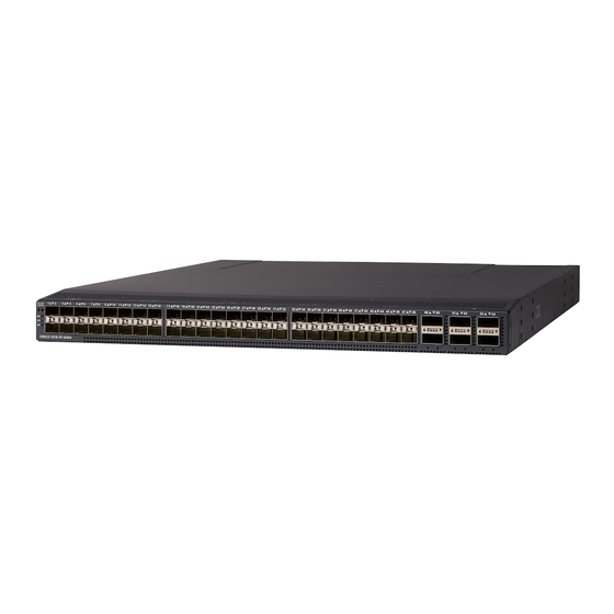
For additional information about the port groups, see Port Numbering, on page The Cisco UCS 6454 Fabric Interconnect chassis has two power supplies and four fans. Two of the fans provide front to rear airflow. Figure 2: Cisco UCS 6454 Fabric Interconnect Front View... - Page 9 If the port is connected to another device, this may cause traffic disruption. The port can be disabled and enabled after it has been configured. The following table summarizes the second, third and fourth generation ports for the Cisco UCS fabric interconnects.
-
Page 10: Port Numbering
Port Numbering Ports on the Cisco UCS 6454 Fabric Interconnect are numbered and grouped according to their function. The ports are numbered top to bottom and left to right. The following figure shows the port numbering. Figure 3: Rear View of Cisco UCS 6454 Fabric Interconnect Port Numbers Ports 1–8. -
Page 11: Power Supplies
The fabric interconnect has two power supplies that are accessible from the front of the chassis. The two power supplies support 1+1 redundancy. The Cisco UCS 6454 Fabric Interconnect and the UCS 6300 Series Fabric Interconnect utilize the same power supplies. -
Page 12: Fan Modules
Fan Modules The Cisco UCS 6454 Fabric Interconnect supports four fan modules. The fans support 3+1 redundancy. The Cisco UCS 6454 Fabric Interconnect and the UCS 6300 Series Fabric Interconnect utilize the same model fans. -
Page 13: Management Port Leds
Right Blinking green Activity System Environment LEDs The system environment LED states are listed below. LED State Description Solid amber Minor fan alarm (a fan is missing or there is a failure) Cisco UCS 6454 Fabric Interconnect Hardware Installation Guide... -
Page 14: Port Leds
SFP28 copper twinax cables with integrated transceivers, SFP Fibre Channel transceivers, QSFP transceivers, QSFP28 transceivers, and QSFP cables. Except where noted, both the Cisco UCS 6454 Fabric Interconnect support all the transceivers listed in this section. Ports 1–8 operate as unified ports that are capable of 10/25-Gbps fixed Ethernet, 10/25-Gbps FCoE, or 8-, 16-, or 32 Gbps Fibre Channel ports. -
Page 15: Sfp 1-Gigabit Transceivers
10GBASE-LR SFP+ module (single-mode fiber [SMF], S-Class) FET-10G Cisco 10G Line Extender for FEX SFP-10G-ER Cisco 10GBASE-ER Module SFP-10G-ER-S Cisco SFP-10G-ER-S module (S-Class) SFP-10G-ZR Cisco SFP-10G-ZR module SFP-10G-ZR-S Cisco SFP-10G-ZR-S module (S-Class) Cisco UCS 6454 Fabric Interconnect Hardware Installation Guide... - Page 16 10GBASE-AOC SFP+ cable 1 meter SFP-10G-AOC2M 10GBASE-AOC SFP+ cable 2 meter SFP-10G-AOC3M 10GBASE-AOC SFP+ cable 3 meter SFP-10G-AOC5M 10GBASE-AOC SFP+ cable 5 meter SFP-10G-AOC7M 10GBASE-AOC SFP+ cable 7 meter SFP-10G-AOC10M 10GBASE-AOC SFP+ cable 10 meter Cisco UCS 6454 Fabric Interconnect Hardware Installation Guide...
-
Page 17: Qsfp Transceivers And Cables
802.3X/802.1Qbb Priority Pauses. SFP-10G-LR is supported between fabric interconnect and FEX, but the 300 m limit still applies. QSFP Transceivers and Cables The Cisco 6454 Fabric Interconnect supports Cisco 40GGBASE and 100GBASE Quad Small Form Factor (QSFP) transceiver modules. Table 4: Supported QSFP Transceivers and Cables... -
Page 18: Sfp Fibre Channel Transceivers
Cisco 100GBASE SFP28 active direct-attach optical cable, 25 meter QSFP-100G-AOC30M Cisco 100GBASE SFP28 active direct-attach optical cable, 30 meter SFP Fibre Channel Transceivers The UCS 6454 Fabric Interconnect supports the SFP Fibre Channel transceivers listed below. Table 5: SFP Fiber Channel Transceivers Model Description... - Page 19 32-Gbps Fibre Channel LW SFP+, LC Note The maximum length of fiber optic runs from the fabric interconnect to a chassis is limited to 300 meters. This restriction is imposed by the use of 802.3X/802.1Qbb Priority Pauses. Cisco UCS 6454 Fabric Interconnect Hardware Installation Guide...
- Page 20 Product Overview SFP Fibre Channel Transceivers Cisco UCS 6454 Fabric Interconnect Hardware Installation Guide...
-
Page 21: Installing The Cisco Ucs Fabric Interconnect
Statement 1017 Warning Only trained and qualified personnel must be allowed to install, replace, or service this equipment. Statement 1030 Cisco UCS 6454 Fabric Interconnect Hardware Installation Guide... -
Page 22: Installation Options
You can install the Cisco UCS Fabric Interconnect in a perforated or solid-walled EIA cabinet or an open EIA rack (the Cisco R Series Rack is an ideal choice) using the rack-mount kit. For instructions on installing the fabric interconnect using the rack-mount kit shipped with the chassis, see Installing the Cisco UCS Chassis in a Cabinet or Rack. -
Page 23: Required Equipment
• Ensure that the fabric interconnect is adequately grounded. If the fabric interconnect is not mounted in a grounded rack, Cisco recommends connecting both the system ground on the fabric interconnect and the power supply ground to an earth ground. -
Page 24: Cabinet And Rack Requirements
• Standard 19 in. (48.3 cm) (four-post EIA cabinet or rack, with mounting rails that conform to English universal hole spacing per section 1 of ANSI/EIA-310-D-1992. • The minimum vertical rack space per Cisco UCS 6454 fabric interconnect must be one RU (rack unit), equal to 1.75 in. (4.4 cm). -
Page 25: Requirements Specific To Perforated Cabinets
• The roof should be perforated with at least a 20 percent open area. • The cabinet floor should be open or perforated to enhance cooling. The Cisco R Series racks meet or exceed all these requirements. Requirements Specific to Standard Open Racks In addition to the requirements listed in the , if mounting the chassis in an open rack (no side panels or doors), the minimum vertical rack space per chassis must be one RU (rack unit), equal to 1.75 in. -
Page 26: Installing The Cisco Ucs Chassis In A Cabinet Or Rack
• Effect of damage on the installation Installing the Cisco UCS Chassis in a Cabinet or Rack This section describes how to use the rack-mount kit provided to install a Cisco UCS Chassis into a cabinet or rack that meets the requirements described in... - Page 27 Installing the Cisco UCS Fabric Interconnect Installing the Cisco UCS Chassis in a Cabinet or Rack Quantity Part Description 10-32 x 3/4-inch Phillips pan-head screws Rack-mount guides Slider rails Procedure Step 1 Install the front rack-mount brackets as follows: a) Position a front rack-mount bracket against the chassis and align the screw holes as shown below. You can attach the front rack-mount bracket at the front or the rear of the chassis, depending on which side you want to locate on the cold aisle.
- Page 28 Installing the Cisco UCS Fabric Interconnect Installing the Cisco UCS Chassis in a Cabinet or Rack Front rack-mount bracket Four M4 screws used to aligned to the front of the attach the bracket to the chassis chassis Rear rack-mount guide...
- Page 29 Installing the Cisco UCS Fabric Interconnect Installing the Cisco UCS Chassis in a Cabinet or Rack Figure 8: Sliding the Chassis Into the Rack Step 5 Stabilize the chassis in the rack by attaching the front rack-mount brackets to the front rack-mounting rails: a) Insert 2 screws (12-24 or 10-32, depending on rack type) in each the two front rack-mount brackets (using a total of four screws) and into the threaded holes in the vertical rack-mounting rail.
-
Page 30: Establishing System Ground
Commercial building is located in High Best grounding recommendations an area where lightning storms must be closely followed. frequently occur but is not subject to direct lightning strikes. Cisco UCS 6454 Fabric Interconnect Hardware Installation Guide... -
Page 31: Preventing Electrostatic Discharge Damage
Electrostatic discharge (ESD) damage, which can occur when modules or other devices are improperly handled, results in intermittent or complete failures. Modules consist of printed circuit boards that are fixed in metal carriers. Electromagnetic interference (EMI) shielding and connectors are integral components of the carrier. Cisco UCS 6454 Fabric Interconnect Hardware Installation Guide... - Page 32 • Always use an ESD wrist strap and ensure that it makes maximum contact with bare skin. • ESD grounding straps are available with banana plugs, metal spring clips, or alligator clips. All Cisco UCS Fabric Interconnects are equipped with a banana plug connector (identified by the ground symbol next to the connector) somewhere on the front panel.
-
Page 33: Grounding The Fabric Interconnect
Insert the stripped end of the grounding cable into the open end of the grounding lug. Step 3 Use the crimping tool to secure the grounding cable in the grounding lug. Step 4 Remove the adhesive label from the grounding pad on the fabric interconnect. Cisco UCS 6454 Fabric Interconnect Hardware Installation Guide... -
Page 34: Starting The System
Do not connect the Ethernet port to the LAN until the initial system configuration has been performed. For instructions on configuring the system, see the Configuration Guide for the version of Cisco UCS Manager that you are using. The configuration guides are available at this URL: http://www.cisco.com/c/en/us/support/... - Page 35 For a first-time installation, you will need to work with your network manager to determine the following parameters: • System name • Password for the admin account. Choose a strong password that meets the guidelines for Cisco UCS Manager passwords. This password can not be blank. • Management port IP address and subnet mask •...
- Page 36 Complete the worksheets provided in Site Preparation Checklist for future reference. Step 13 Configure the primary fabric interconnect as described in thr Configuration Guide for the version of Cisco UCS Manager that you are using. The configuration guides are available at this URL: http://www.cisco.com/...
-
Page 37: Connecting The Cisco Ucs Fabric Interconnect
• Fibre Channel ports to connect to a SAN. When preparing your site for network connections to the Cisco UCS Fabric Interconnect, consider the following for each type of interface, and gather all the required equipment before connecting the ports: •... - Page 38 Connecting the Cisco UCS Fabric Interconnect Connecting to the Console Port The console port on a Cisco UCS fabric interconnect provides an RS-232 serial connection over an RJ-45 interface. This interface can be used for the following tasks: • Perform initial setup on a newly installed system that does not yet have other connectivity options •...
-
Page 39: Connecting The Management Port
Connecting the Cisco UCS Fabric Interconnect Connecting the Management Port You now have terminal access. Depending on the prompt, you may have all Cisco UCS Manager CLI commands or a very abbreviated set of configuration commands. Connecting the Management Port... -
Page 40: Removing A Transceiver
Press the SFP28 transceiver inward and upward into the cage. Next, lower the bale clasp and pull the SFP28 transceiver straight out with a slight upward lifting force. Be careful not to damage the port cage during this process. Cisco UCS 6454 Fabric Interconnect Hardware Installation Guide... -
Page 41: Installing Or Removing Cables Into Sfp28 Trancsceivers
If the cable does not install easily, ensure that it is correctly positioned before continuing. For instructions on verifying connectivity, see the Configuration Guide for the version of Cisco UCS Manager that you are using. The configuration guides are available at this URL: http://www.cisco.com/c/en/us/support/... -
Page 42: Maintaining Sfp28 Transceivers And Fiber-Optic Cables
Refer to fiber-optic cleaning procedures for your site. • Inspect routinely for dust and damage. If damage is suspected, clean and then inspect fiber ends under a microscope to determine if damage has occurred. Cisco UCS 6454 Fabric Interconnect Hardware Installation Guide... -
Page 43: Replacing Components
Disable the Smart Call Home feature in the Cisco UCS domain. d) Decommission every attached chassis in the Cisco UCS domain. For details, see the Configuration Guide for the version of Cisco UCS Manager that you are using. The configuration guides are available at this URL: http://www.cisco.com/c/en/us/support/... -
Page 44: Removing A Cisco Ucs Fabric Interconnect
Procedure Step 1 Ensure that the weight of the Cisco UCS Fabric Interconnect is fully supported and that the chassis is being held by another person. Step 2 Remove the two screws holding the grounding cable to the chassis. - Page 45 Install the replacement fabric interconnect. Follow the instructions in this section for installing the fabric interconnect. Step 9 Connect the management and console cables to the replacement fabric interconnect. Step 10 Connect the L1/L2 cables that were disconnected to the replacement fabric interconnect. Cisco UCS 6454 Fabric Interconnect Hardware Installation Guide...
- Page 46 Installer has detected the presence of a peer Fabric interconnect. This Fabric interconnect will be added to the cluster. Continue (y/n) ? y Enter the admin password of the peer Fabric interconnect: Connecting to peer Fabric interconnect... done Cisco UCS 6454 Fabric Interconnect Hardware Installation Guide...
- Page 47 A: memb state UP, lead state PRIMARY, mgmt services state: UP B: memb state UP, lead state SUBORDINATE, mgmt services state: UP heartbeat state PRIMARY_OK INTERNAL NETWORK INTERFACES: eth1, UP eth2, UP HA READY <<<<<<<<<<<<<←---------------- HA is READY Cisco UCS 6454 Fabric Interconnect Hardware Installation Guide...
-
Page 48: Repacking The Cisco Ucs Fabric Interconnect For Return Shipment
If you need to return the fabric interconnect, remove the fabric interconnect from the rack and repack it for shipment. If possible, use the original packing materials and container to repack the unit. Contact your Cisco customer service representative to arrange for return shipment to Cisco. -
Page 49: Technical Specifications
AC or two DC power supplies with the fabric interconnect. In addition, if you use a DC power supply, you must use two corresponding DC power cords. The Cisco UCS 6454 Fabric Interconnect and the UCS 6300 Series Fabric Interconnect utilize the same power supplies. - Page 50 Technical Specifications Power Specifications Note You cannot mix power supply types in a Cisco UCS Fabric Interconnect. Table 9: Specifications for the Cisco UCS 6332 AC Power Supply (UCS-PSU-6332-AC) AC Power Supply Properties Cisco UCS 6332 Fabric Interconnect Maximum output per power supply...
-
Page 51: Transceiver Specifications
General Specifications for Cisco Fibre Channel SFP Transceivers The table below lists the general specifications for Cisco Fibre Channel SFP transceivers at 4 Gbps. Table 13: General Specifications for Cisco Fibre Channel SFP Transceivers at 4 Gbps Description... - Page 52 Technical Specifications General Specifications for Cisco Fibre Channel SFP Transceivers Description Short Wavelength Transmit power -9 to -2.5 dBM Approximate; actual distance may vary depending on fiber quality and other factors. Cisco UCS 6454 Fabric Interconnect Hardware Installation Guide...
-
Page 53: Cable And Port Specifications
C H A P T E R Cable and Port Specifications • Accessory Kit for the Cisco UCS Fabric Interconnect, on page 47 • Console Cable, on page 48 • Console Port, on page 48 • Supported AC Power Cords and Plugs, on page 49... -
Page 54: Console Cable
Signal Name Console Port The console port is an asynchronous RS-232 serial port with an RJ-45 connector. The table below lists the pinouts for the console port on the Cisco UCS 6454 Fabric Interconnect. Table 15: Console Port Pinouts Signal... -
Page 55: Supported Ac Power Cords And Plugs
IEC C14 connector on the end that plugs into an IEC C13 outlet receptacle. Note Only the regular power cords or jumper power cords provided with the chassis are supported. Argentina Power Cord—SFS-250V-10A-AR Plug—250 VAC 10 A IRAM 2073 Length—8.2 feet / 2.5 meters Cisco UCS 6454 Fabric Interconnect Hardware Installation Guide... -
Page 56: Australia And New Zealand
Cordset rating: 10 A, 250 V/500V Length: 2500mm Connector: Plug: EL 701C EL 206 (IEC 60320/C15) A.S. 3112-2000) Peoples Republic of China Power Cord—SFS-250V-10A-CN Plug—250 VAC 10 A GB 2009 Length—8.2 feet / 2.5 meters Cisco UCS 6454 Fabric Interconnect Hardware Installation Guide... -
Page 57: Europe
Cordset rating: 10A/16 A, 250 V Length: 8 ft 2 in. (2.5 m) Plug: M2511 Connector: VSCC15 India, South Africa, and United Arab Emirates Power Cord—SFS-250V-10A-ID Plug—250 VAC 16A EL-208 Length—8.2 feet / 2.5 meters Cisco UCS 6454 Fabric Interconnect Hardware Installation Guide... -
Page 58: Israel
Figure 16: SFS-250V-10A-IS Cordset rating 10A, 250V/500V MAX (2500 mm) Connector: EL 701B Plug: (IEC60320/C13) EL 212 (SI-32) Italy Power Cord—CAB-9K10A-IT Plug—250 VAC 10 A CEI 23-16 Length—8.2 feet / 2.5 meters Cisco UCS 6454 Fabric Interconnect Hardware Installation Guide... -
Page 59: North America
North America CAB-AC-250V/13A Power Cord—CAB-AC-250V/13A Plug—250 VAC 13 A IEC60320 Length—6.6 feet / 2.0 meters Figure 18: CAB-AC-250V/13A CAB-N5K6A-NA Power Cord—CAB-N5K6A-NA Plug—250 VAC 13 A NEMA 6-15 Length—8.2 feet / 2.5 meters Cisco UCS 6454 Fabric Interconnect Hardware Installation Guide... -
Page 60: Switzerland
Figure 20: CAB-9K10A-SW Cordset rating: 10 A, 250 V Length: 8.2 ft Plug: NEMA 6-15P Connector: IEC60320/C13 Taiwan Power Cord—CAB-ACTW Plug—125 VAC, 10 A, CNS10917 Length—7.5 feet / 2.3 meters Figure 21: CAB-ACTW Cisco UCS 6454 Fabric Interconnect Hardware Installation Guide... -
Page 61: United Kingdom
Jumper Power Cord—CAB-C13-C14-JMPR Plug— 250 VAC 10 A, C13-C14 Connectors Length—2.2 feet / 0.7 meters Figure 23: CAB-C13-C14-JMPR Jumper Power Cord—CAB-C13-C14-AC Plug— 250 VAC 10 A, C13-C14 Connectors Length—9.8 feet / 3 meters Cisco UCS 6454 Fabric Interconnect Hardware Installation Guide... - Page 62 Cable and Port Specifications Cabinet Jumper Power Cords Figure 24: CAB-C13-C14-AC Jumper Power Cord—CAB-C13-C14-2M Plug— 250 VAC 10 A, C13-C14 Connectors Length—6.6 feet / 2 meters Figure 25: CAB-C13-C14-2M Cisco UCS 6454 Fabric Interconnect Hardware Installation Guide...
-
Page 63: Site Planning And Maintenance Records
Consider heat dissipation when sizing the air-conditioning requirements for an installation. Table 16: Site Planning Checklist Task No. Planning Activity Verified By Time Date Space evaluation: • Space and layout • Floor covering • Impact and vibration • Lighting • Maintenance access Cisco UCS 6454 Fabric Interconnect Hardware Installation Guide... - Page 64 • Dedicated circuit for power supply • Dedicated (separate) circuits for redundant power supplies • UPS for power failures Grounding evaluation: • Circuit breaker size • CO ground (AC- powered systems) Cisco UCS 6454 Fabric Interconnect Hardware Installation Guide...
-
Page 65: Contact And Site Information
Use the following worksheet to record contact and site information. Table 17: Contact and Site Information Contact person Contact phone Contact e-mail Building/site name Data center location Floor location Address (line 1) Address (line 2) Cisco UCS 6454 Fabric Interconnect Hardware Installation Guide... -
Page 66: Chassis And Module Information
System IP address System IP netmask Hostname Domain name IP broadcast address Gateway/router address DNS address Modem telephone number Table 19: Module Information Slot Module Type Module Serial Number Notes Fixed Expansion Cisco UCS 6454 Fabric Interconnect Hardware Installation Guide... - Page 67 Chassis and Module Information Table 20: Fabric Interconnect Port Connection Record Fabric Interconnect A or B Connected to Slot Port Chassis Port LAN or SAN Port Connection Pin Group Channel Notes Group Cisco UCS 6454 Fabric Interconnect Hardware Installation Guide...
- Page 68 Site Planning and Maintenance Records Chassis and Module Information Fabric Interconnect A or B Connected to Slot Port Chassis Port LAN or SAN Port Connection Pin Group Channel Notes Group Cisco UCS 6454 Fabric Interconnect Hardware Installation Guide...
Need help?
Do you have a question about the UCS 6454 and is the answer not in the manual?
Questions and answers