ABB 10D1475 Installation Instructions Manual
Magnetic flowmeter
Hide thumbs
Also See for 10D1475:
- Instruction manual (55 pages) ,
- Instruction manual (52 pages) ,
- Instruction manual (57 pages)
Advertisement
Advertisement
Table of Contents

Related Manuals for ABB 10D1475


Summary of Contents for ABB 10D1475
- Page 1 INSTALLATION INSTRUCTIONS Magnetic Flowmeter Models 10D1475/1476/1477 PN25001A...
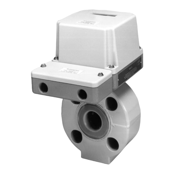
- Page 2 INSTALLATION INSTRUCTIONS GENERAL This installation instruction literature serves as a guide for proper in- stallation of the associated magnetic flowmeter. A more detailed de- scription of installation procedures will be found in the Instruction Bulletin provided for the particular magnetic flowmeter primary. FIGURE 1.
-
Page 3: Tips & Techniques
INSTALLATION INSTRUCTIONS TIPS & TECHNIQUES FIGURE 2. Recommended Piping Diagram Mounting hardware (supplied by ABB) consists of: studs, nuts, gas- kets and adapter(s).Check itemized packing list to be certain that all items listed have been received. -
Page 4: Conduit Connections
This tag highlights the installation techniques necessary for depend- able service from your ABB Magnetic Flowmeter. By observing and performing these operations, your meter warranty remains valid and satisfactory performance is assured. Coverage of all recommenda- tions given in this instruction is provided in detail within the Instruction Manual which accompanies your meter. -
Page 5: Mounting Procedure
INSTALLATION INSTRUCTIONS MOUNTING PROCEDURE INSTALLATION OF 1/10 - 3/8 INCH METERS • Align flange adapter on meter body, as shown below. • Install a gasket at meter inlet and outlet, as applicable for meter type. Observe flow direction arrow. • Insert meter with (with gaskets) between pipe flanges. - Page 6 INSTALLATION INSTRUCTIONS INSTALLATION OF 1/2 - 4 INCH METERS • Install a gasket at meter inlet and outlet, as applicable for meter type. • Insert meter (with gaskets) between pipe flanges. • Insert two lower mounting studs with adaptor sleeves between pipe flanges.
-
Page 7: Grounding Procedure
( Refer to FIGURE 6 ) • Customer must supply install bonding strap (e.g., 1/2" copper braid) from meter body to an external earth ground. FIGURE 6. Grounding Procedure, Conductive Pipeline NOTE Refer to appropriate Instruction Bulletin supplied by ABB for electrical interconnection diagram(s). - Page 8 • Refer to Figure 8 for optional grounding ring dimensions. FIGURE 7. Grounding Procedure, Non-Conductive Pipeline NOTE Refer to applicable Instruction Bulletin supplied by ABB for electrical interconnection diagram(s).
- Page 9 • The grounding ring material must be con- ductive and not sub- ject chemical reaction with the me- tered fluid. • Grounding rings are available from ABB (2 required). ( Refer to FIGURE 8 ) FIGURE 8. Outline Dimensions of Accessory Grounding Rings...
- Page 10 The Company’s policy is one of continuous product improvement and the right is reserved to modify the information contained herein without notice. © 2004 ABB Inc. Printed in USA ABB Inc. ABB Instrumentation Ltd ABB Instrumentation S.p.A ABB Automation Products GmbH 125 East County Line Road Howard Road, St.
Need help?
Do you have a question about the 10D1475 and is the answer not in the manual?
Questions and answers