Siemens SIMOTICS SD Operating Instructions Manual
Low-voltage motors
Hide thumbs
Also See for SIMOTICS SD:
- Operating instructions manual (142 pages) ,
- Compact operating instructions (166 pages) ,
- Compact operating instructions (26 pages)
Table of Contents
Advertisement
Quick Links
Advertisement
Table of Contents

Related Manuals for Siemens SIMOTICS SD


Summary of Contents for Siemens SIMOTICS SD
- Page 3 ___________________ Low-voltage motors Introduction ___________________ Safety information ___________________ Description SIMOTICS GP, SD, DP, XP ___________________ Preparing for use Low-Voltage Motors ___________________ Low-voltage motors Assembly ___________________ Electrical connection Operating Instructions ___________________ Commissioning ___________________ Operation ___________________ Maintenance ___________________ Spare parts ___________________ Disposal ___________________ Appendix ___________________...
- Page 4 Note the following: WARNING Siemens products may only be used for the applications described in the catalog and in the relevant technical documentation. If products and components from other manufacturers are used, these must be recommended or approved by Siemens. Proper transport, storage, installation, assembly, commissioning, operation and maintenance are required to ensure that the products operate safely and without any problems.
-
Page 5: Table Of Contents
Table of contents Introduction ............................. 9 About these instructions ......................... 9 Information for the reader ......................9 Safety information ..........................11 Information for those responsible for the plant or system ............11 The five safety rules ........................11 Qualified personnel ........................12 The safe use of electrical machines..................... - Page 6 Table of contents 5.1.6 Balancing............................. 35 5.1.6.1 Mounting and withdrawing output transmission elements ............36 5.1.7 Noise emission ..........................37 Alignment and fastening ......................37 5.2.1 Flatness of supporting surfaces ....................38 5.2.2 Machine frame mounting feet (special design) ................38 Electrical connection ..........................
- Page 7 Table of contents Operation .............................. 73 Safety instructions ........................73 8.1.1 Safety instructions during operation..................... 73 8.1.2 Safety information for explosion-protected machines in operation ..........75 8.1.3 Safety instructions for cleaning ....................76 8.1.4 Machines with textile fan covers ....................76 Stoppages ............................
- Page 8 Dismantling the machine ......................113 11.4 Disposal of components ......................114 Appendix ............................. 115 SIEMENS Service Center ......................115 Languages of operating instructions available in the Internet ........... 115 Further documents ........................116 Technical data and drawings ........................ 117 Exploded drawings ........................117 B.1.1...
-
Page 9: Introduction
Introduction About these instructions These instructions describe the machine and explain how to handle it, from initial delivery to final disposal of the equipment. Keep these instructions for later use. Read these operating instructions before you handle the machine and follow the instructions to become familiar with its design and operating principles and thus ensure safe, problem- free machine operation and long service life. - Page 10 Introduction 1.2 Information for the reader Low-voltage motors Operating Instructions, 05/2014, 5 610 00000 02 000...
-
Page 11: Safety Information
Safety information Information for those responsible for the plant or system This electric machine has been designed and built in accordance with the specifications contained in Directive 2006/95/EC ("Low-Voltage Directive") and is intended for use in industrial plants. Please observe the country-specific regulations when using the electric machine outside the European Community. -
Page 12: Qualified Personnel
Safety information 2.3 Qualified personnel Qualified personnel All work at the machine must be carried out by qualified personnel only. For the purpose of this documentation, qualified personnel is taken to mean people who fulfill the following requirements: ● Through appropriate training and experience, they are able to recognize and avoid risks and potential dangers in their particular field of activity. -
Page 13: Safety Instructions: Explosion-Proof Machines
If any deviations or uncertainties arise, contact the manufacturer specifying the type designation and serial number (see rating plate) or have the equipment repaired by a Siemens Service Center. Special conditions for explosion-proof machines Special conditions for the safe application of explosion-protected machines marked with X (excerpt from the EC type-examination certificate, point 17) Flameproof enclosure "d"... - Page 14 Safety information 2.7 Special conditions for explosion-proof machines Low-voltage motors Operating Instructions, 05/2014, 5 610 00000 02 000...
-
Page 15: Description
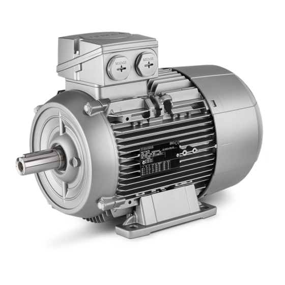
Description Area of application Overview The three-phase machines of this series are used as industrial drives. They are designed for a wide range of drive applications both for line operation as well as in conjunction with frequency converters. They are characterized by their high power density, extreme robustness, long service life and outstanding reliability. -
Page 16: Rating Plates
Description 3.2 Rating plates Rating plates Rating plate The rating plate shows the identification data and the most important technical data. The data on the rating plate and the contractual agreements define the limits of proper usage. Data on the rating plate Item Description Item... -
Page 17: Installation
Description 3.3 Installation Figure 3-1 Examples of rating plates Installation 3.3.1 Machine design Machines of this series are low-voltage three-phase asynchronous drives with a cylindrical shaft end and featherkey way. They can be supplied as single-speed machines with different efficiency classes or as pole changing machines for several speeds. In the case of machines with feet (IM B3 type of construction), the feet are cast or bolted on. -
Page 18: Regulations
Description 3.3 Installation 3.3.2 Regulations Standard motors The regulations and standards used as basis to design and test this machine are stamped on the rating plate. The machine design basically complies with the following standards: Table 3- 1 Applicable general regulations Feature Standard Dimensioning and operating behavior... -
Page 19: Cooling And Ventilation
Description 3.3 Installation 3.3.3 Cooling and ventilation 3.3.3.1 General The machines of this series are three-phase asynchronous machines with a closed primary (internal) cooling circuit and an open secondary cooling circuit (surface cooling). The surface cooling varies depending on the version. 3.3.3.2 Machines with a fan Self-ventilation (standard): Cooling IC 411 in accordance with EN / IEC 60034-6... -
Page 20: Machines Without A Fan (Optional)
Description 3.3 Installation Forced ventilation (optional): Type of cooling IC 416 in accordance with EN / IEC 60034-6 WARNING Risk of burning Operating the machine without external fan results in overheating. This may result in personal injury and material damage. Never commission the machine without an external fan. -
Page 21: Bearings
Description 3.3 Installation Surface cooling by relative movement of cooling air: Type of cooling IC 418 in accordance with EN / IEC 60034-6 Figure 3-3 IC418 3.3.4 Bearings In order to support the machine shaft and maintain its position in the non-moving part of the machine, only 2 rolling-contact bearings are used. -
Page 22: Types Of Construction/Method Of Installation
Description 3.3 Installation 3.3.6 Types of construction/method of installation WARNING Damage caused by small parts falling in Material damage and injury can occur if the fan is destroyed and therefore the motor overheats. • For types of construction with a shaft extension facing downwards, a suitable cover must be fitted to prevent small parts from falling into the fan cover (see also standard IEC / EN 60079-0). - Page 23 Description 3.3 Installation Basic type of Diagram Other methods of Diagram construction code installation IM B5 (IM 3001) IM V1 (IM 3011) IM V3 (IM 3031) Basic type of Diagram Other methods of Diagram construction code installation IM B14 (IM 3601) IM V18 (IM 3611) IM V19 (IM 3631) Basic type of...
-
Page 24: Degree Of Protection
• Protect the motor against intensive solar radiation, rain, snow, ice and dust. Use a superstructure or additional cover, for example. • If required, contact the Siemens Service Center, or technically coordinate outdoors use. Environmental requirements The machine is suitable for tropical climates. -
Page 25: Optional Built-On And Built-In Accessories
Description 3.3 Installation Installation altitude: ≤ 1000 m Air with normal oxygen content, usually 21 % (V/V) If the environmental requirements are different from the details listed here, then the values on the rating plate will apply. Machines intended for use in Zone 1 (type of protection Flameproof Enclosure "d" or Increased Safety "e") or in Zone 2 (type of protection "n") are designed with IP 55 degree of protection. - Page 26 Description 3.3 Installation Low-voltage motors Operating Instructions, 05/2014, 5 610 00000 02 000...
-
Page 27: Preparing For Use
The drive systems are put together on an individual basis. When you take receipt of the delivery, please check immediately whether the items delivered are in accordance with the accompanying documents. Siemens will not accept any claims relating to items missing from the delivery and which are submitted at a later date. -
Page 28: Storage
Preparing for use 4.3 Storage WARNING Toppling over or slipping of the motor The motor can slide or topple over if it is not correctly lifted or transported. This can result in death, serious injury, or material damage. • Use all the lifting eyes on the machine. •... -
Page 29: Electromagnetic Compatibility
Preparing for use 4.4 Electromagnetic compatibility locate machines, equipment and crates on pallets, wooden beams or foundations. Prevent equipment from sinking into the ground. Do not impede air circulation under the stored items. Covers or tarpaulins used to protect the equipment against the weather must not come into contact with the surfaces of the equipment. - Page 30 Preparing for use 4.4 Electromagnetic compatibility Note Converter • If operated with a frequency converter, the emitted interference varies in strength, depending on the design of the converter (type, interference suppression measures, manufacturer). • Avoid that the specified limit values stipulated for the drive system (consisting of the motor and converter) are exceeded.
-
Page 31: Assembly
Assembly Installation 5.1.1 Safety instructions WARNING Risk of burning Electrical machines have hot surfaces. Fatal or severe injuries and substantial material damage can occur if the required covers are removed or if the machines are not handled, operated, or maintained properly. •... -
Page 32: Machine Installation
Assembly 5.1 Installation 5.1.3 Machine installation General Note In order to prevent the eyebolts loosening, after mounting, tighten these or remove them. NOTICE Damage to mounted components Material damage can occur if you use the mounted components to help lift the motor. Do not use the mounted components to help lift the motor. -
Page 33: Cooling
Assembly 5.1 Installation 5.1.4 Cooling 5.1.4.1 Ventilation CAUTION Overheating and failure of the motor Material damage or slight injury can occur if you do not observe the following points: • Do not obstruct ventilation. • Prevent the air expelled by neighboring equipment from being immediately sucked in again. -
Page 34: Machines With Type Of Construction Im B15, Im B9, Im V8 And Im V9
Assembly 5.1 Installation Table 5- 2 Minimum dimension "X" for the distance between neighboring modules and the air intake of the machine Frame size [mm] 63 ... 71 80 ... 100 180 ... 225 180 ... 200 (1LG) 225 ... 250 (1LG, 1MA6) 280 ... -
Page 35: Balancing
Assembly 5.1 Installation 5.1.6 Balancing CAUTION Incorrect mounting or removal To avoid injury and material damage, carefully observe general touch protection measures for output transmission elements. • The general touch protection measures for drive output elements must be observed. • Output elements may only be attached or withdrawn using the correct equipment. •... -
Page 36: Mounting And Withdrawing Output Transmission Elements
Assembly 5.1 Installation 5.1.6.1 Mounting and withdrawing output transmission elements Withdrawing output transmission elements Mounting output transmission elements ● When mounting output transmission elements (coupling, gear wheel, belt pulley etc. ) use the thread at the shaft end. If possible, heat up the output transmission elements as required. ●... -
Page 37: Noise Emission
Assembly 5.2 Alignment and fastening 5.1.7 Noise emission CAUTION Hearing damage when operating three-phase motors If you exceed the permissible sound pressure level, hearing damage can occur when operating three-phase motors at their rated power. Observe the maximum permissible sound pressure level according to the ISO 1680 standard. -
Page 38: Flatness Of Supporting Surfaces
Assembly 5.2 Alignment and fastening alignment of the coupling, as well as a well-balanced transmission element (coupling, belt pulleys, fans, etc.), are prerequisites for smooth running with low vibration. Maximum permissible vibration in operation according to ISO 10816 must be complied with. -
Page 39: Electrical Connection
Electrical connection Connecting the machine 6.1.1 General DANGER Hazardous voltages Death, injury or material damage can occur. Note the following safety information before connecting-up the machine: • Only qualified and trained personnel should carry out work on the machine while it is stationary. - Page 40 Electrical connection 6.1 Connecting the machine The technical specifications stipulate the following that have to be taken into account with respect to the motor connection: ● Direction of rotation. ● The number and arrangement of the terminal boxes. ● The circuit and connection of the machine winding. The following features make this type of electrical connection different from that for standard machines: ●...
-
Page 41: Terminal Designations
Electrical connection 6.1 Connecting the machine 6.1.2 Terminal designations With the terminal designations according to DIN VDE 0530 Part 8 or EN / IEC 60034-8 for three-phase machines, the following principle definitions apply: Table 6- 1 Terminal designations (with the 1U1-1 as an example) Designation Index showing the pole assignment for pole-changing machines (where applicable, a lower number indicates a lower speed) or, in special cases, for a... -
Page 42: Connection With Cable Lug For Explosion-Protected Machines
Electrical connection 6.1 Connecting the machine 6.1.5 Connection with cable lug for explosion-protected machines WARNING Short-circuit hazard Live conductors released from the terminal board can cause short circuits. Death or serious physical injury can result. • You must bend single-core line conductors into a U shape in order to prevent the contact force being transferred at just one side. -
Page 43: Mounting Position Of Sheet Metal Nuts In Screw-Type Connections
Electrical connection 6.1 Connecting the machine Cable glands with reductions and (sheet metal) nuts (EN 50262) ① O ring ② 6.1.7.1 Mounting position of sheet metal nuts in screw-type connections ② O ring Mounting position of metal-sheet ③ nuts Cable glands with connecting thread in the terminal box (EN 50262) ②... -
Page 44: Terminal Box
Electrical connection 6.1 Connecting the machine 6.1.8 Terminal box 6.1.8.1 General DANGER Hazardous voltage Electric motors have high voltages. When incorrectly handled, this can result in death or severe injury. Switch off the machine so that it is in a no-voltage condition before you open the terminal box. -
Page 45: Versions
Electrical connection 6.1 Connecting the machine WARNING Hazardous voltage Loosening the safety torx screw can result in death, serious injury or material damage. Do not loosen the safety torx screw with respect to the center terminal, as this ensures a conductive connection between the grounding conductor and frame! NOTICE Serious damage to the machine... - Page 46 Electrical connection 6.1 Connecting the machine Installation instructions ③ ① 1. Press the three large snap hooks over the flange of the terminal box towards the inside. ③ 2. Hold the snap hooks pressed inwards, detach the terminal box, raise it slightly and rotate it to the required POSITION.
-
Page 47: Protruding Connection Cables
IIC are available as an option. Please note in this regard design, connection options and spare parts. Note the explosion protection information designated with in the operating instructions! Have authorized Siemens workshops perform any repairs. 6.1.8.3 Protruding connection cables WARNING... -
Page 48: Connecting The Temperature Sensor/Anti-Condensation Heater
Electrical connection 6.1 Connecting the machine CAUTION Damage to connecting cables that are freely led out You must observe the following note to avoid damaging connecting cables that are freely led out: • It must be ensured that there are no foreign bodies, dirt, or moisture in the terminal base of the machine enclosure. - Page 49 Electrical connection 6.1 Connecting the machine The temperature sensor / anti-condensation heater is connected in the terminal box. Table 6- 2 Connection to terminal strip Aluminum Cast iron Connection at the temperature sensor using a spring-loaded connection system ① Flat-head screwdriver ②...
-
Page 50: Cable Entry
Electrical connection 6.1 Connecting the machine 6.1.8.5 Cable entry Knockout openings NOTICE Damage to the terminal box You must observe the following notes to avoid damaging the terminal box: • Knockout openings in the terminal box must be knocked out using appropriate methods. •... -
Page 51: Thread Sizes In Terminal Box
Electrical connection 6.1 Connecting the machine Cable entries for explosion-proof machines The cable glands must have an EC-type examination certificate and be certified for the respective hazardous zone. ● Any openings that are not being used must be sealed using the corresponding certified plugs. - Page 52 Electrical connection 6.1 Connecting the machine Frame size Type Type of protection / Standard thread Additional Zone thread with mounting parts 1MA6 Increased safety "e" M 50x1.5 M 16x1.5 1MJ6 Zone 21 1MJ6 Flameproof enclosure "d" M 50x1.5 M 20x1.5 Zone 21 1LG4 Non sparking "n"...
-
Page 53: Tightening Torques
Electrical connection 6.2 Tightening torques Frame size Type Type of protection / Standard thread Additional Zone thread with mounting parts 1LA7 Increased safety "e" M 40x1.5 1LA9 Non sparking "n" 1MA7 Zone 21 Zone 22 1MB1 Non sparking "n" M 40x1.5 M 16x1.5 Zone 21 Zone 22... -
Page 54: Cable Glands
Electrical connection 6.2 Tightening torques 6.2.2 Cable glands Note Avoid damaging the cable jacket. Adapt the tightening torques to the cable jacket materials. You should refer to the table in order to find the correct tightening torque for any metal and plastic cable glands that are to be mounted directly on the machine, as well as for any other screw-type connections (such as adapters). -
Page 55: Conductor Connection
Electrical connection 6.3 Conductor connection Table 6- 8 Tightening torques for self-tapping screws on the terminal box, end shields, screw-type grounding conductor connections, sheet metal fan covers Thread ∅ 12,5 15,5 Conductor connection 6.3.1 General information on conductor connection Cross-sections that can be connected depending on the size of the terminal (possibly reduced due to size of cable entries) WARNING Short-circuit hazard... -
Page 56: Type Of Conductor Connection
Electrical connection 6.3 Conductor connection Table 6- 10 Max. conductor connection for explosion-proof machines (with the exception of Zone 22 and 1MJ) and VIK standard version Frame size Max. connectable conductor cross-section [mm²] 56 ... 112 16,0 10,0 180 (1LG4, 1LG6) 16,0 200 ... - Page 57 Electrical connection 6.3 Conductor connection Terminal plate Conductor cross- section [mm²] Bend down the cable lug for the connection! 1MA618. … 10 1MA620. … 35 Connection of an individual conductor with terminal clamp 1MA618..20. … 25 Connection of two conductors of the same thickness with terminal clamp 1MA618.
- Page 58 Electrical connection 6.3 Conductor connection Connecting terminal Conductor cross- section [mm²] 1MA618..22. 2,5 … 25 1MA625..28. 10 … 95 1MA631. 25 … 135 1MA631. + L00 50 … 300 1MA618..22. … 16 1MA625..28. …...
-
Page 59: Connecting The Grounding Conductor
Electrical connection 6.4 Connecting the grounding conductor Recommended connection variants ① Cable lugs DIN 46237 with insulating sleeve (round and open) ② Rigid cable (insulation removed at ends ≤ 8 mm) ③ End sleeves DIN 46228 ≤ 8 mm If air gaps ≥ 5.5 mm (up to 690 V) are observed between non-insulated components, you can also use alternative connection elements without insulating sleeve, for example cable lugs acc. -
Page 60: Grounding Connection Type
Electrical connection 6.4 Connecting the grounding conductor 6.4.2 Grounding connection type Enclosure grounding method Conductor cross- section [mm²] Connection of an individual conductor under the external grounding bracket. … 10 Connection is made using a DIN cable lug under the external grounding bracket. -
Page 61: Minimum Surface Area Of Grounding Conductor
Electrical connection 6.4 Connecting the grounding conductor 6.4.3 Minimum surface area of grounding conductor Table 6- 12 Minimum cross-sectional area of grounding conductor Minimum cross-sectional area of phase Minimum surface area of associated grounding conductor for installation connection [mm²] [mm²] S ≤... -
Page 62: Size Of Grounding Conductor Screw
Electrical connection 6.5 Final measures 6.4.4 Size of grounding conductor screw Table 6- 13 Size of grounding conductor screw external grounding (except for 1MJ machines) Frame size Thread size for the grounding conductor 63 ... 90 M3.5 / M4 100 ... 112 132 ... -
Page 63: Connecting Optional Mounted Components
Electrical connection 6.6 Connecting optional mounted components Connecting optional mounted components 6.6.1 External fan, incremental encoder, brake See the list of additional operating instructions: Further documents (Page 116) Select mounted components such as external fans, incremental encoders or brakes according to the requirements of the directive 94/9/EG . 6.6.1.1 Mounting a brake Table 6- 15... -
Page 64: Connecting Converters
Electrical connection 6.7 Connecting converters Connecting converters NOTICE Excessively high supply voltage Material damage can occur if the supply voltage is too high for the insulation system. The standard insulation system is designed so that converter operation is possible for line voltages up to U ≤... - Page 65 Electrical connection 6.7 Connecting converters temperature at the cable entries is 120° C. Use suitable cables for this temperature. Do not exceed the maximum frequency dependent on the number of poles, which is stamped on the rating plate. System, converter-cable-electrical machine Please observe the information in accordance with EN / IEC 60034-17 and EN / IEC 60034- 25 regarding winding stress.
- Page 66 Electrical connection 6.7 Connecting converters Table 6- 17 Explosion-proof motors in Zones 2, 21 and 22 with type of protection "n" or protection against dust explosions (motor series 1LA, 1LG) Motor- Motor type 2-pole 6-pole 8-pole pole frame size 1LA5, 1LA6, 1LA7, 1LA9 56 M 1LA7/1LA9 6000...
-
Page 67: Commissioning
Commissioning Insulation resistance 7.1.1 Testing the insulation resistance WARNING Hazardous voltage at the terminals Only appropriately trained personnel may carry out this work. Hazardous voltages are sometimes present at the terminals during and immediately after measurement of the winding insulation resistance. If you touch the terminals, this can result in death, serious injury or material damage. - Page 68 Commissioning 7.1 Insulation resistance Measuring the insulation resistance 1. Before you begin measuring the insulation resistance, please read the operating manual for the insulation resistance meter you are going to use. 2. Disconnect any connected main-circuit cables from the terminals before measuring the insulation resistance.
-
Page 69: Measures Before Start-Up
If the critical insulation resistance is reached or fallen below, this can result in damage to the insulation or voltage flashovers. • Contact your Siemens Service Center. • If the measured value is close to the critical value, you must check the insulation resistance at suitably frequent intervals. - Page 70 Commissioning 7.2 Measures before start-up Measures Once the system has been correctly installed, you should check the following prior to commissioning: ● The machine has been assembled and aligned correctly. ● The machine has been connected so that it rotates in the direction specified. ●...
-
Page 71: Switching On
Commissioning 7.3 Switching on If the design of the machine requires the converter to be assigned in a particular way, the relevant information will be provided on the rating plate or an additional label. Note It may be necessary to perform additional checks and tests in accordance with the specific situation on site. - Page 72 Commissioning 7.3 Switching on ● If it runs perfectly, connect a load. Check that it runs smoothly, and read off and document the values for voltage, current and power. As far as possible, read off and document the corresponding values for the driven machine as well. NOTICE Damage to the motor If you do not maintain the permissible vibration values, this can either damage or...
-
Page 73: Operation
Operation Safety instructions 8.1.1 Safety instructions during operation Switching on the machine with anti-condensation heating (optional) CAUTION Machine overheating Slight injury or material damage can occur if you do not observe the following: Switch off the (optional) anti-condensation heating before switching on. Machine operation DANGER Hazardous voltages... - Page 74 Operation 8.1 Safety instructions WARNING Risk of burning Electrical machines have hot surfaces. Fatal or severe injuries and substantial material damage can occur if the required covers are removed or if the machines are not handled, operated, or maintained properly. Do not touch the machine in operation and wait until the machine has completely cooled down.
-
Page 75: Safety Information For Explosion-Protected Machines In Operation
Operation 8.1 Safety instructions CAUTION Risk of injury when touching the fan There is a risk of injury at machines equipped with a fan cover for the textile industry, as the fan is not completely touch protected. • Do not touch the rotating fan. •... -
Page 76: Safety Instructions For Cleaning
Operation 8.2 Stoppages 8.1.3 Safety instructions for cleaning Cleaning To ensure problem-free machine cooling, the air ducts (ventilation grilles, channels, cooling fins, tubes) must be free of pollution. WARNING Explosion hazard It is forbidden to clean the machine in an explosive atmosphere. This can result in death, serious injury or material damage. - Page 77 Operation 8.2 Stoppages Switching on the anti-condensation heater If an anti-condensation heater is provided, switch it on during the machine stoppages. Taking the machine out of service For details of measures that need to be implemented, please refer to Section Preparing for use (Page 27).
-
Page 78: Fault Tables
Operation 8.3 Fault tables Fault tables Note Before removing any faults, please read the information in Chapter Safety information (Page 11). Note If you operate the motor with a converter, and an electrical fault occurs, then also observe the information in the converter operating instructions. The tables below list general faults caused by mechanical and electrical influences. - Page 79 Operation 8.3 Fault tables Table 8- 2 Mechanical effects Mechanical fault characteristics ↓ Grinding noise ↓ Overheating ↓ Radial vibrations ↓ Axial vibrations Possible causes of faults Remedial measures Rotating parts are grinding Determine cause and adjust parts concerned Reduced air supply, fan possibly rotating in the wrong Check airways, clean machine direction Rotor not balanced.
-
Page 80: Deactivating
Operation 8.4 Deactivating Deactivating Commission any devices provided for protection against condensation after switching off the machine. Class 8.5.1 Zone 1 with type of protection Ex de IIC Gb (flameproof enclosure "d" for the machine and increased safety "e" for the terminal box) ①... -
Page 81: Zone 1 With Ex E Iic Gb Type Of Protection (Increased Safety "E")
Operation 8.5 Class 8.5.2 Zone 1 with Ex e IIC Gb type of protection (increased safety "e") ① ② ③ ④ ⑤ ⑥ ⑦ ⑧ ⑨ ⑩ ⑪ ① ② ③ ⑫ ⑦ ⑧ ⑨ ⑩ ⑪ ⑬ ① CE - or EAC marking ②... -
Page 82: Zone 1 With Ex E Iib Gb Type Of Protection (Increased Safety "E")
Operation 8.5 Class 8.5.3 Zone 1 with Ex e IIB Gb type of protection (increased safety "e") ① ② ③ ④ ⑤ ⑥ ⑦ ⑧ ⑨ ⑩ ⑪ ① ② ③ ⑫ ⑦ ⑧ ⑨ ⑩ ⑪ ⑬ ① CE - or EAC marking ②... -
Page 83: Zone 2 With Type Of Protection Ex Na Iic Gc, Non Sparking
Operation 8.5 Class 8.5.4 Zone 2 with type of protection Ex nA IIC Gc, non sparking ① ② ③ ④ ⑤ ⑥ ⑦ ⑧ ⑨ ⑩ ① ⑪ ② ⑫ ⑥ ⑦ ⑧ ⑨ ⑩ ⑬ ① CE - or EAC marking ②... -
Page 84: Zone 2 With Type Of Protection Ex Na Iib Gc, Non Sparking
Operation 8.5 Class 8.5.5 Zone 2 with type of protection Ex nA IIB Gc, non sparking ① ② ③ ④ ⑤ ⑥ ⑦ ⑧ ⑨ ⑩ ① ⑪ ② ⑫ ⑥ ⑦ ⑧ ⑨ ⑩ ⑬ ① CE - or EAC marking ②... -
Page 85: Zone 21
Operation 8.5 Class 8.5.6 Zone 21 IIIC T125°C ① ② ③ ④ ⑤ ⑥ ⑦ ⑧ ⑨ ⑩ ⑪ IIIC T125°C ① ② ③ ⑦ ⑧ ⑨ ⑩ ⑪ ⑫ ① CE - or EAC marking ② Identification number or name of nominated testing agency ③... -
Page 86: Zone 22
Operation 8.5 Class 8.5.7 Zone 22 IIIB T125°C ① ② ③ ④ ⑤ ⑥ ⑦ ⑧ ⑨ ⑩ IIIB T125°C ① ⑪ ② ⑥ ⑦ ⑧ ⑨ ⑩ ⑫ ① CE - or EAC marking ② Code for prevention of explosions ③... -
Page 87: Maintenance
Preparation and notes for explosion-protected machines ● Only have the machines repaired in authorized Siemens workshops! ● For machines intended for use in hazardous areas, only have modifications, repairs and overhaul work carried out by appropriately qualified personnel. -
Page 88: North American Market
Maintenance 9.1 Preparation and notes 9.1.1 North American market Machines for the North American market (optional) When making changes or repairs, maintain the corresponding design standards! These machines are labeled on the rating plate with the following markings. Table 9- 1 Markings for the North American market Underwriters Laboratories Canadian Standard Association... - Page 89 Maintenance 9.1 Preparation and notes Table 9- 2 Applicable general regulations Feature Standard Dimensioning and operating behavior EN / IEC 60034-1 GOST R IEC 60034-1 Procedure for determining the losses and the efficiency of rotating electrical EN / IEC 60034-2-1 GOST R IEC 60034- machines and inspections EN / IEC 60034-2-2...
-
Page 90: Touch Up Any Damaged Paintwork
Maintenance 9.1 Preparation and notes 9.1.3 Touch up any damaged paintwork If the paint is damaged, it must be repaired in order to protect the unit against corrosion. Note Paint system Contact the Service Center before you repair any paint damage. They will provide you with more information about the correct paint system and methods of repairing paint damage. -
Page 91: Inspection
Maintenance 9.2 Inspection Inspection 9.2.1 General inspection specifications Notes Note Pay particular attention to the relubrication intervals for rolling bearings that deviate from the inspection intervals. Note When servicing a three-phase machine, it is generally not necessary to dismantle it. The machine only has to be dismantled if the bearings are to be replaced. -
Page 92: Main Inspection
Maintenance 9.2 Inspection ● The motor foundation must have no indentations or cracks. Note Additional checks and tests may be required. Observe the associated supplementary instructions and special plant/system-specific conditions Note Rectify any impermissible deviations immediately. 9.2.4 Main inspection Inspection interval Inspect the machine once a year. -
Page 93: Maintenance
Maintenance 9.3 Maintenance Maintenance 9.3.1 Maintenance intervals CAUTION Skin irritations and eye inflammations Many greases can cause skin irritations and eye inflammations. Follow all safety instructions of the manufacturer. The machines are equipped with permanently lubricated roller bearings. A regreasing device is optional. -
Page 94: Regreasing (Optional)
Maintenance 9.3 Maintenance 9.3.2 Regreasing (optional) For machines with regreasing system, relubrication intervals, grease quantity and grease grade are provided on the lubricant plate. Additional data can be taken from the main machine rating plate. Grade of grease for standard motors (IP55) UNIREX N3 - ESSO). Note It is not permissible to mix different types of grease. -
Page 95: Drain Condensate
Maintenance 9.3 Maintenance Cleaning the cooling air passages Regularly clean the cooling air passages through which the ambient air flows, e.g. using dry compressed air. Note Never direct compressed air in the direction of the shaft outlet or machine openings. In the case of machines with textile fan covers, regularly remove fluff balls, fabric remnants, and similar types of contamination (particularly at the air passage opening between the fan cover and cooling fins of the machine enclosure) to ensure that the cooling air can flow... -
Page 96: Corrective Maintenance
Maintenance 9.4 Corrective maintenance Corrective maintenance 9.4.1 Instructions for repair Qualified personnel Only appropriately qualified persons should be deployed to commission and operate equipment. Qualified persons, as far as the safety instructions specified in this manual are concerned, are those who have the necessary authorization to commission, ground and identify/tag equipment, systems and circuits in accordance with the relevant safety standards. -
Page 97: Changing Bearings
Maintenance 9.4 Corrective maintenance Replacing bearings Recommended interval after which bearings are to be replaced under normal operating conditions: Table 9- 5 Bearing replacement intervals Ambient temperature Principle of operation Bearing replacement intervals 40° C Horizontal coupling operation 40 000 h 40°... -
Page 98: Replacing Bearings In Explosion-Proof Machines
9.4 Corrective maintenance 9.4.2.2 Replacing bearings in explosion-proof machines ● When changing the bearings, renew the sealing rings and only use original Siemens spare parts. ● When installing the sealing rings for the motor series 1LA., 1MA.06. to 20., 1MJ6., fill completely the space in the sealing ring and in the end shield hub with a suitable type of grease. -
Page 99: Bearing Bushes
Maintenance 9.4 Corrective maintenance 9.4.3.1 Bearing bushes Protect the bearings against the ingress of dirt and moisture. 9.4.3.2 Links ● Replace any corroded screws. ● Take care not to damage the insulation of live parts. ● Document the position of any rating and supplementary plates that have been removed. ●... -
Page 100: Fitting Bearings
Maintenance 9.4 Corrective maintenance 9.4.4.3 Fitting bearings Sealing the bearings Note the following details: ● Shaft sealing rings are used to seal machines at the rotor shaft. For V rings, comply with the assembly dimension. ● Use the specified bearings. ●... -
Page 101: Mounting The Fan Cover
Maintenance 9.4 Corrective maintenance 9.4.4.5 Mounting the fan cover Fan cover ● When fitting the cover, do not overstretch it (risk of breakage). ● First engage two snap openings positioned next to one other, then carefully press the cover into position with the two openings situated opposite these using the snap-in lugs, and snap it into place. -
Page 102: Screw Lock Washers
Maintenance 9.4 Corrective maintenance 9.4.5 Screw lock washers Nuts or bolts that are mounted together with locking, resilient and/or force-distributing elements (e.g., safety plates, spring-lock washers, etc.) must be refitted together with identical, fully functional elements. Always replace locking elements. 9.4.6 Electrical connections - Termincal board connections Table 9- 6... -
Page 103: Terminal Boxes, End Shields, Grounding Conductors, Sheet Metal Fan Covers
Maintenance 9.4 Corrective maintenance Table 9- 7 Tightening torques for cable glands Metal Plastic Clamping range [mm] O ring ± 10% Cord dia. Standard [Nm] ± 10% [mm] -30 °C ... 100 °C [Nm] -30 °C ... 90 °C -60 °C ... 105 °C M 12 x 1.5 3,0 ... -
Page 104: Optional Add-On Units
Maintenance 9.4 Corrective maintenance 9.4.9 Optional add-on units See the list of additional operating instructions: Appendix (Page 115) Table 9- 10 Assigning standard brakes for 1LE1 machines Frame size Brake type Size assignment of the Tightening torque of manual brakes lifting lever (BG) 2LM8 010–3NA10... -
Page 105: Spare Parts
● Order number and serial number of the machine Spare parts information and database Using the Siemens order number and the associated serial number, you can download spare parts information from a database for almost all current motors → Spares On Web (https://b2b-extern.automation.siemens.com/spares_on_web) -
Page 106: Ordering Example
The following supply commitment apply to replacement machines and spare parts following delivery of the motor: ● For up to five years, in the event of total machine failure, Siemens will supply a comparable machine with regard to the mounting dimensions and functions. -
Page 107: Machine Parts
Spare parts 10.3 Machine parts 10.3 Machine parts Part Description Part Description 1.00 DE bearings Terminal box, complete 1.30 Bolt 5.30 Rubber stopper (1MA618.-20.) 1.31 Spring lock washer according to SN 60727 5.31 Terminal clamp (1MA618.-20.) 1.32 Bolt 5.32 Angle (1MA618.-20.) 1.33 5.33 Washer (1MA618.-20.) - Page 108 Spare parts 10.3 Machine parts Part Description Part Description 4.14 5.85 Terminal box cover including seal (optional screw) 4.18 Rating plate 5.86 Protection mark 4.19 Self-tapping screw 5.87 Bolt 4.20 Cover 5.88 Spring lock washer according to SN 60727 4.30 Contact bracket 5.89 Bolt...
- Page 109 Spare parts 10.3 Machine parts Part Description Part Description 7.41 bracket 7.47 Sleeve 7.48 Spring lock washer according to SN 60727 7.49 Bolt Tools for mounting and withdrawing roller bearings; fans and output transmission elements cannot be supplied. Low-voltage motors Operating Instructions, 05/2014, 5 610 00000 02 000...
-
Page 110: Standardized Parts
Spare parts 10.4 Standardized parts 10.4 Standardized parts Table 10- 3 Purchase commercially available standard parts according to the dimensions, materials and surface. Standard Picture Standard Picture DIN 471 DIN 939 3.02 1.30 6.02 1.31 DIN 6912 7.12 1.32 1.45 DIN 472 1.49 DIN 7964... - Page 111 Spare parts 10.4 Standardized parts Table 10- 4 Purchase commercially available standard parts according to the dimensions, materials and surface. Standard Picture Standard Picture EN ISO 4014 DIN 472 6.02 (FS 160) 1.49 EN ISO 4017 (frame size 132/160) 4.04 DIN 580 4.11 EN ISO 4762...
- Page 112 Spare parts 10.4 Standardized parts Low-voltage motors Operating Instructions, 05/2014, 5 610 00000 02 000...
-
Page 113: Disposal
Disposal 11.1 Introduction Protecting the environment and preserving its resources are corporate goals of the highest priority for us. Our worldwide environmental management system to ISO 14001 ensures compliance with legislation and sets high standards in this regard. Environmentally friendly design, technical safety and health protection are always firm goals even at the product development stage. -
Page 114: Disposal Of Components
Disposal 11.4 Disposal of components 11.4 Disposal of components Components The machines consist mainly of steel and various proportions of copper and aluminum. Metals are generally considered to be unlimitedly recyclable. Sort the components for recycling according to whether they are: ●... -
Page 115: Appendix
On-site service calls and spare parts If you wish to request on-site service calls or order spare parts, please contact your local Siemens sales office. This office will contact the responsible service center on your behalf. You can find your local contact partner here. -
Page 116: Further Documents
Appendix A.3 Further documents Further documents These operating instructions can also be obtained at the following Internet site: http://www.siemens.com/motors General Documentation 1.517.30777.30.000 1XP8001 encoder 5 610 00000 02 000 Operating_Instructions_Simotics GP, SD, DP, XP 5 610 00000 02 001 Operating_Instructions_Compact_Simotics GP, SD, DP... -
Page 117: Technical Data And Drawings
Technical data and drawings Exploded drawings B.1.1 1LA,1LP,1MA,1MF,1PP6/7/9 FS 56 ... 90L Low-voltage motors Operating Instructions, 05/2014, 5 610 00000 02 000... -
Page 118: 1La,1Lp,1Ma,1Mf,1Pp6/7/9 Fs 100
Technical data and drawings B.1 Exploded drawings B.1.2 1LA,1LP,1MA,1MF,1PP6/7/9 FS 100 ... 160 Low-voltage motors Operating Instructions, 05/2014, 5 610 00000 02 000... -
Page 119: 1La5180
Technical data and drawings B.1 Exploded drawings B.1.3 1LA5180 ... 225 Low-voltage motors Operating Instructions, 05/2014, 5 610 00000 02 000... -
Page 120: 1Ma6180
Technical data and drawings B.1 Exploded drawings B.1.4 1MA6180 ... 200 Low-voltage motors Operating Instructions, 05/2014, 5 610 00000 02 000... -
Page 121: Terminal Boxes 1Ma6180
Technical data and drawings B.1 Exploded drawings B.1.5 Terminal boxes 1MA6180 ... 200 Low-voltage motors Operating Instructions, 05/2014, 5 610 00000 02 000... -
Page 122: 1Mj6070
Technical data and drawings B.1 Exploded drawings B.1.6 1MJ6070 ... 200 Low-voltage motors Operating Instructions, 05/2014, 5 610 00000 02 000... -
Page 123: Terminal Boxes 1Mj6070
Technical data and drawings B.1 Exploded drawings B.1.7 Terminal boxes 1MJ6070 ... 160 Low-voltage motors Operating Instructions, 05/2014, 5 610 00000 02 000... -
Page 124: Terminal Boxes 1Mj6180
Technical data and drawings B.1 Exploded drawings B.1.8 Terminal boxes 1MJ6180 ... 200 (Ex e) Low-voltage motors Operating Instructions, 05/2014, 5 610 00000 02 000... -
Page 125: Terminal Boxes 1Mj6180
Technical data and drawings B.1 Exploded drawings B.1.9 Terminal boxes 1MJ6180 ... 200 (Ex d) Low-voltage motors Operating Instructions, 05/2014, 5 610 00000 02 000... -
Page 126: 1Le1/ 1Mb1 Bg 80
Technical data and drawings B.1 Exploded drawings B.1.10 1LE1/ 1MB1 BG 80 ... 160 aluminum Low-voltage motors Operating Instructions, 05/2014, 5 610 00000 02 000... -
Page 127: 1Le1 / 1Mb1 Bg 100
Technical data and drawings B.1 Exploded drawings B.1.11 1LE1 / 1MB1 BG 100 ... 200 cast iron Low-voltage motors Operating Instructions, 05/2014, 5 610 00000 02 000... -
Page 128: 1Le1 / 1Mb1 Bg 225
Technical data and drawings B.1 Exploded drawings B.1.12 1LE1 / 1MB1 BG 225 ... 315 cast iron Low-voltage motors Operating Instructions, 05/2014, 5 610 00000 02 000... -
Page 129: 1Lg4/6 Fs 180
Technical data and drawings B.1 Exploded drawings B.1.13 1LG4/6 FS 180 ... 315 Low-voltage motors Operating Instructions, 05/2014, 5 610 00000 02 000... -
Page 130: Terminal Box Gk330, Gt320, Gk430, Gt420
Technical data and drawings B.1 Exploded drawings B.1.14 Terminal box gk330, gt320, gk430, gt420 Low-voltage motors Operating Instructions, 05/2014, 5 610 00000 02 000... -
Page 131: Terminal Box Gk431, Gt421, Gt520, Gt540
Technical data and drawings B.1 Exploded drawings B.1.15 Terminal box gk431, gt421, gt520, gt540 Low-voltage motors Operating Instructions, 05/2014, 5 610 00000 02 000... -
Page 132: Terminal Box 1Lg4/6 Gt620, Gt640, Gt791
Technical data and drawings B.1 Exploded drawings B.1.16 Terminal box 1LG4/6 gt620, gt640, gt791 Low-voltage motors Operating Instructions, 05/2014, 5 610 00000 02 000... -
Page 133: Glossary
Glossary Drive end (DE) Operating instructions CE marking Code F Balanced with whole featherkey (full) Code H Balanced with half featherkey (half) Canadian Standard Association CSA E Canadian Standard Association Energie Efficiency Verification Coolant temperature Drive end (D end of shaft) Zollunion Eurasien - Eurasian Customs Union EC type examination certificate Evidence of a machine certified by an inspection body... - Page 134 Glossary Internet www.siemens.com/motors Degree of protection ISPM International Standards for Phytosanitary Measures N code Balanced without featherkey (non2) Non-drive end NE/NDE Non-drive end Shaft height Underwriters Laboratories Verband der industriellen Energie- und Kraftwirtschaft e.V. (German Association of Industrial Energy Users and Self-Generators) Zone 1 Atmosphere: Gas;...
-
Page 135: Index
Rating plate, 16 Correct usage, 16 Repainting, 90 Disassembly Service Center, 115 Disposal, 113 Service numbers, 115 Disposal Siemens Service Center, 115 Chemicals, 114 Spare parts, 115 Components, 114 Field service visits, 115 Five safety rules, 11 Insulation resistance Critical, 69...
Need help?
Do you have a question about the SIMOTICS SD and is the answer not in the manual?
Questions and answers