Table of Contents
Advertisement
Available languages
Available languages
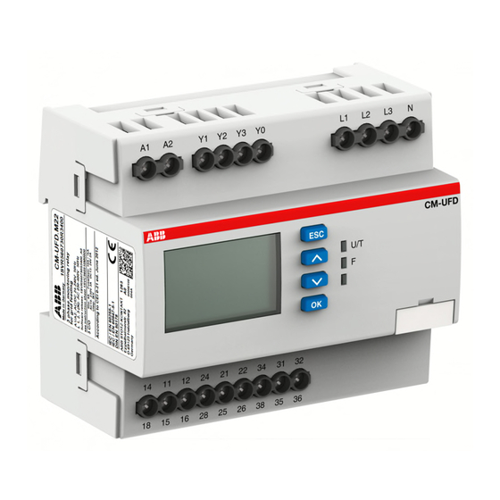
CM-UFD.M22
Warnung! Gefährliche Spannung! Installation nur durch
elektro technische Fachkraft.
Warning! Hazardous voltage! Installation by person with electro-
technical expertise only.
Avertissement! Tension électrique dangereuse! Installation
uniquement par des personnes qualifiées en électrotechnique.
¡Advertencia! ¡Tensión peligrosa! La instalación deberá ser
realizada únicamente por electricistas especializados.
Avvertenza! Tensione pericolosa! Far installare solo da un
elettricista specializzato.
Varning! Farlig spänning! Installation får endast utföras av en
elektriker.
Oсторожно! Опасное напряжение! Монтаж должен
выполняться только специалистом-электриком.
(IT) Istruzioni per l'uso ed il montaggio
Relè di protezione di interfaccia serie CM
Relè di protezione di interfaccia in accordo
con la norma CEI 0-21: Connessione di utenti
attivi alle reti di bassa tensione
Nota: Le presenti istruzioni per l'uso ed il montaggio non
contengono tutte le informazioni di dettaglio sull'intera
gamma di prodotti e non possono trattare tutti i casi
applicativi. Tutte le indicazioni servono esclusivamente a
descrivere il prodotto e non costituiscono alcuna
obbligazione
contrattuale.
consultare i cataloghi ed i data sheet dei prodotti, o la
nostra homepage www.abb.com, oppure rivolgersi alla
filiale locale di ABB. Ci riserviamo il diritto di effettuare
eventuali modifiche tecniche.
(EN) Operating and installation instructions
Grid feeding monitoring relay, CM range
Interface protection according to CEI 0-21:
Connection to the low voltage grid
Note: These operating and installation instructions cannot
claim to contain all detailed information of all types of this
product range and can even not consider every possible
application of the products. All statements serve exclusively
to describe the product and have not to be understood as
contractually agreed characteristics. Further information
and data is obtainable from the catalogues and data sheets
of this product, from the local ABB sales organisations as
well as on the ABB homepage www.abb.com. Subject to
change without prior notice.
ABB STOTZ-KONTAKT GmbH, Eppelheimer Straße 82, 69123 Heidelberg / Germany; www.abb.com/lowvoltage
Per
ulteriori
informazioni
1
2
1
2
T
: -20 ... +60 °C (-4 ... +140 °F)
a
IP 20
Pollution degree 3
Nota importante:
Lunghezza massima dei cavi agli ingressi di comando: 10 m
Fusibile di protezione per:
- alimentazione ausiliaria: 6 A gL/gG
- ingresso di misura: fusibile sec. la protezione di linea richiesta
(esempio: 3 x 16 A)
Important notice:
The cable length at the control inputs must not exceed 10 m.
Protection fuse for:
- control supply input: 6 A gL/gG
- measuring input: fuse size acc. to the required line protection
(example: 3 x 16 A)
3
Advertisement
Table of Contents

Related Manuals for ABB CM-UFD.M22


Summary of Contents for ABB CM-UFD.M22
- Page 1 ABB sales organisations as well as on the ABB homepage www.abb.com. Subject to change without prior notice. ABB STOTZ-KONTAKT GmbH, Eppelheimer Straße 82, 69123 Heidelberg / Germany; www.abb.com/lowvoltage...
- Page 2 Vista frontale con gli elementi di comando Front view with operating controls 0.5...0.6 Nm (4.4...5.3 lb.in) Ø 4 mm (0.157") PH 1 1 x 0.2...6 mm² 8 mm 0.315" 2 x 0.2...1.5 mm² (1 x 24...10 AWG 2 x 24...16 AWG) 1 x 0.2...4 mm²...
- Page 3 L1 L2 L3 N Legenda Legend Alimentazione per CM-UFD.M22 (SPI) e dispositivo di sgancio Control supply voltage for the CM-UFD.M22 (SPI) and the trip (DDI)* device coil (DDI)* Bobina di sgancio necessaria per realizzare la funzione di Shunt trip coil for feedback function. This coil can control DG/ rincalzo.
- Page 4 R1 (DDI) si diseccita ed entro il tempo di ritardo impostabile, la CM-UFD.M22 per 4 volte in poco tempo, e potrebbe causare logica interna non riceve un feedback dai contatti esterni mediante instabilità.
- Page 5 Password delay and output relay R2 (21 DG) energizes or de- Tutti i relè CM-UFD.M22 vengono consegnati con la medesima energizes, depending on the configuration, after a fixed delay of password preimpostata [0000): é responsabilità dell’installatore 1 s. Using the default factory setting, both output relays R1 (DDI) verificare i parametri impostati e cambiare la password con una...
- Page 6 Note: We recommend to manually disconnect the generating plant from the grid before executing the auto test procedure. The auto test will cause the CM-UFD.M22 to trip four times within a short time, which may lead to voltage fluctuations in the public grid.
- Page 7 Denominazione delle funzioni di protezione in accordo con la CEI 0-21 Parametri del relè secondo CEI 0-21 Sovra tensione >S1 1a Sovra tensione med. (59 S1) Sovra tensione >S2 2a Sovra tensione (59 S2) Sotto tensione <S1 1a Sotto tensione (27 S1) Sotto tensione <S2 2a Sotto tensione (27 S2) Sovra frequenza >S1...
- Page 8 Sottomenu: Configurazione I/O Contenuto del sottomenu Opzioni Possibilità di configurazione Passo CEI 0-21 Impostazioni relè 1 Ritardo di start-up [1,00] - [600,00] s 0,05 s Ritardo di re-start [0,05] - [600,00] s 0,05 s 0,05 s Impostazioni relè 2 Principio operativo [circuito chiuso], [circuito aperto] circuito chiuso Impostazioni relè...
- Page 9 Sottomenu: Autotest Selezionare „Autotest“ e premere il tasto OK per iniziare la verifica Sottomenu: Impostazioni generali Contenuto del sottomenu Opzioni Possibilità di configurazione Passo Default Comando locale Comando locale [disabilitato], [abilitato] abilitato Cambia password [****] Lingua Lingua [Italiano], [English] Italiano Display Ritardo spegnimento [10] - [600] s...
- Page 10 Designation of the protective functions according to CEI 0-21 Device parameters acc. to CEI 0-21 Overvoltage >S1 1st overvoltage med. (59 S1) Overvoltage >S2 2nd overvoltage (59 S2) Undervoltage <S1 1st undervoltage (27 S1) Undervoltage <S2 2nd undervoltage (27 S2) Overfrequency >S1 1st overfrequency (81>S1) Overfrequency >S2...
- Page 11 Submenu: I/O setup Contents of submenu Options Configuration possibilities Step size CEI 0-21 Relay 1 settings Start-up delay [1.00] - [600.00] s 0.05 s Re-start delay [0.05] - [600.00] s 0.05 s 0.05 s Relay 2 settings Working prinicple [closed-circuit], [open-circuit] closed-circuit Relay 3 settings Working prinicple...
- Page 12 Submenu: Autotest Select “Autotest” and press the OK button to start the verification of the protective functions. Submenu: General settings Contents of submenu Options Configuration possibilities Step size Device default Local command Local command [disabled], [enabled] enabled Change password [****] Language Language [Italiano], [English]...
Need help?
Do you have a question about the CM-UFD.M22 and is the answer not in the manual?
Questions and answers