Pioneer DJM-5000 Service Manual
Hide thumbs
Also See for DJM-5000:
- Operating instructions manual (37 pages) ,
- Operating instructions manual (114 pages) ,
- Operating instructions manual (54 pages)
Table of Contents
Advertisement
Quick Links
DJ MIXER
DJM-5000
THIS MANUAL IS APPLICABLE TO THE FOLLOWING MODEL(S) AND TYPE(S).
Model
Type
DJM-5000
CUXJ
DJM-5000
SYXJ5
DJM-5000
LXJ
DJM-5000
KXJ5
For details, refer to "Important Check Points for good servicing".
PIONEER CORPORATION
PIONEER ELECTRONICS (USA) INC. P.O. Box 1760, Long Beach, CA 90801-1760, U.S.A.
PIONEER EUROPE NV Haven 1087, Keetberglaan 1, 9120 Melsele, Belgium
PIONEER ELECTRONICS ASIACENTRE PTE. LTD. 253 Alexandra Road, #04-01, Singapore 159936
PIONEER CORPORATION
Power Requirement
AC 120 V
AC 220 V to 240 V
AC 110 V to 120 V or 220 V to 240 V
AC 220 V
4-1, Meguro 1-chome, Meguro-ku, Tokyo 153-8654, Japan
2009
DJM-5000
K-IZE SEP.
ORDER NO.
RRV3992
Remarks
2009 Printed in Japan
Advertisement
Table of Contents

Related Manuals for Pioneer DJM-5000


Summary of Contents for Pioneer DJM-5000
- Page 1 PIONEER CORPORATION 4-1, Meguro 1-chome, Meguro-ku, Tokyo 153-8654, Japan PIONEER ELECTRONICS (USA) INC. P.O. Box 1760, Long Beach, CA 90801-1760, U.S.A. PIONEER EUROPE NV Haven 1087, Keetberglaan 1, 9120 Melsele, Belgium PIONEER ELECTRONICS ASIACENTRE PTE. LTD. 253 Alexandra Road, #04-01, Singapore 159936...
-
Page 2: Safety Information
PIONEER Service Manual. A subscription to, or additional copies of, Also test with plug reversed Earth PIONEER Service Manual may be obtained at a nominal (Using AC adapter ground charge from PIONEER. plug as required) - Page 3 To protect products from damages or failures during transit, the shipping mode should be set or the shipping screws should be installed before shipment. Please be sure to follow this method especially if it is specified in this manual. DJM-5000...
-
Page 4: Table Of Contents
10.23 OUTPUT ASSY (1/4) ..............................96 10.24 OUTPUT ASSY (2/4) ..............................98 10.25 OUTPUT ASSY (3/4) ..............................100 10.26 OUTPUT ASSY (4/4) ..............................102 10.27 PWR SECONDARY ASSY............................104 10.28 PRIMARY, PWR SW and TRANS ASSYS ......................106 10.29 STANDBY and REG ASSYS...........................108 10.30 VOLTAGES................................109 10.31 WAVEFORMS .................................113 DJM-5000... - Page 5 11.6 PANEL B ASSY ................................ 136 11.7 CH1, CH2, CH3, CH4 and CRS FADER ASSYS...................... 140 11.8 OUTPUT ASSY ................................ 142 11.9 PWR SECONDARY ASSY ............................146 11.10 PRIMARY, PWR SW, TRANS, STANDBY and REG ASSYS.................. 148 12. PCB PARTS LIST ................................152 DJM-5000...
-
Page 6: Service Precautions
Compared with eutectic solders, lead-free solders have higher bond strengths but slower wetting times and higher melting temperatures (hard to melt/easy to harden). The following lead-free solders are available as service parts: • Parts numbers of lead-free solder: GYP1006 1.0 in dia. GYP1007 0.6 in dia. GYP1008 0.3 in dia. DJM-5000... -
Page 7: Specifications
2. SPECIFICATIONS 2.1 SPECIFICATIONS DJM-5000... -
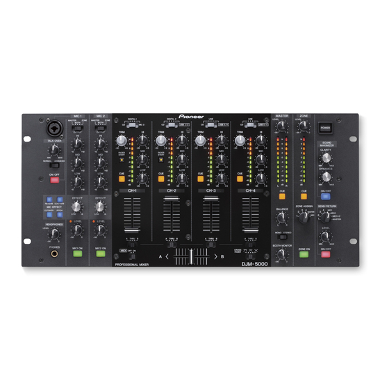
Page 8: Panel Facilities
2.2 PANEL FACILITIES [1] Control Panel DJM-5000... - Page 9 [2] Rear Panel (for LXJ) (for CUXJ, SYXJ5 and KXJ5) (for LXJ) DJM-5000...
-
Page 10: Basic Items For Service
No scratches or dirt on its appearance after receiving it for service. See the table below for the items to be checked regarding audio. Item to be checked regarding audio Distortion Noise Volume too low Volume too high Volume fluctuating Sound interrupted DJM-5000... -
Page 11: Pcb Locations
ZONE JACK ASSY Chassis section (Top) MIC 1 AMP ASSY PWR SW ASSY INPUT ASSY PRIMARY ASSY DAC ASSY REG ASSY HP JACK ASSY TRANS ASSY Chassis section (Bottom) OUTPUT ASSY USB/DIG JACK ASSY STANDBY ASSY MAIN ASSY PWR SECONDARY ASSY DJM-5000... - Page 12 Parts marked by “NSP” are generally unavailable because they are not in our Master Spare Parts List. The > mark found on some component parts indicates the importance of the safety factor of the part. Therefore, when replacing, be sure to use parts of identical designation. LIST OF ASSEMBLIES DJM-5000 DJM-5000 DJM-5000 DJM-5000...
-
Page 13: Jigs List
Dedicated cable for connector conversion used for firmware download. GGF1605 Interface device used for firmware download. GGP1174 (x2) 29P FFC used for diagnosis of MAIN Assy. Lubricants and Glues List Name Part No. Remarks Silicon grease ZLB-PN600 Refer to “9.3 BOTTOM SECTION”. DJM-5000... -
Page 14: Block Diagram
PANEL A ASSY PANEL B ASSY 13 NC 14 VRSEL1_b1 VRSEL1_b1 (DWX2961) 15 VRSEL1_b0 (DWX2962) VRSEL1_b0 16 VR_IN0 VR_IN0 VR_IN1 17 VR_IN1 18 VR_IN2 VR_IN2 19 GNDREF1 GNDREF1 20 V+3R3VREF1 V+3R3VREF1 GNDREF1 21 GNDREF1 V+3R3VREF1 22 V+3R3VREF1 FADER ASSY (DWX2968) DJM-5000... - Page 15 4P FFC L=50mm 4P FFC L=50mm 4P FFC L=50mm 4P PH L=100mm Straight Straight Straight Straight : The power supply is shown with the marked box. ER ASSY FADER ASSY FADER ASSY FADER ASSY FADER ASSY X2968) (DWX2969) (DWX2970) (DWX2971) (DWX2972) DJM-5000...
-
Page 16: Block Diagram
AK4387 IC2039 IC3904 NJM4565MD IC2016 IC3402 IC2012 NJM4565MD PCM1804 NJM4565MD NJM4565MD IC3401 LINE NJM4565MD IC3904 IC3402 IC3404 IC2008 NJM4580MD NJM4565MD NJM4565MD IC2039 TC74LVX4052F IC3501 NJM4565MD MIC1 IC2020 IC3501 AK5381VT NJM4565MD MIC2 IC4010 NJM4565MD RETURN(L) IC2024 IC4010 NJM4565MD AK5358A RETURN(R) DJM-5000... - Page 17 IC3701 NJM4565MD IC3703 NJM4580MD IC1007 MAIN_CPU IC1011 uPD78F1166 FPGA ROM: 256k DYW1782 XC3S50-4TQG144C-T IC1019 IC1020 PANEL A and B SDRAM (64M) FLASH (4M) IC1006 FADER K4S641632K S29AL004D70 SUB_CPU IN_SEL TFI010-K uPD78F1164 KEY MATRIX DYW1784 ROM: 128k LED MATRIX DYW1783 DJM-5000...
-
Page 18: Diagnosis
Cancel the reset of the sub Pin 73 of IC1007 cancels microcomputer. sub microcomputer reset at H. Handshake with the DSP Note: The DPRAM access is impossible. Sub microcomputer Wait time: 10 msec initialization wait DIR initial setting Initial setting of the main computer DJM-5000... - Page 19 Set a mask level to MUTE cancellation. Pin 87 of IC1006 starts Waiting for FPGA start FPGA at H. confirmation Main processing In Test Mode? Test Mode In MIDI CH configuration mode? MIDI CH configuration mode processing Normal operation mode Main processing DJM-5000...
- Page 20 Main power DIR_SCK00 Be "Hi" states after the power DIR_SEL1 supply from Main power Wait for TUSB initialization completion USB_SBY Cancel the DAC reset for digital input DIGI_IN_DAC_RST Cancel the MUTE MUTE (Master Mute) About 4770 msec DJM-5000...
- Page 21 (95) el reset Main<=>DSP (100msec) Waiting handshake (24 msec) for DAC stability necessary. DIR initialization ( 110 us ) DIR and DAC are active Low 1440 msec DIR and DAC are active Low Low after initialization completion 1580 msec DJM-5000...
-
Page 22: Service Mode
MIC1 MASTER MIC2 MIC1+2 MASTER LEVEL LEVEL HEAD PHONES LEVEL LEVEL MONO STEREO THRU THRU THRU THRU BOOTH MONITOR PHONES MIC1 ON MIC2 ON CROSS ZONE ON ON/OFF MIDI OFF ON FADER DJM-5000 PROFESSIONAL MIXER Test Mode: CANCEL POWER DJM-5000... - Page 23 OCTAVER DSP (data) PITCH FPGA MIC1 ON T-USB 2 Mode 2 : All LED ”OFF” Mode The mode that all LED turns off the light. 3 Mode 2 : All LED ”ON” Mode The mode which all LED lights. DJM-5000...
- Page 24 ZONE CUE ZONE CUE LED ZONE ON ZONE ON LED SOUND MAXIMIZER ON/OFF SOUND MAXIMIZER ON/OFF LED SEND&RETURN ON/OFF SEND&RETURN ON/OFF LED AUTO STANDBY Only for the EUP type. AUTO STANDBY MST LEVEL LED 14 dB Two LED lights. DJM-5000...
- Page 25 MASTER Level Meter R SELECT -4 dB -2 dB MASTER 0 dB -15 dB -10 dB -7 dB -4 dB SEND & RETURN ZONE Level Meter SELECTOR -2 dB MIC1 0 dB MIC2 2 dB MIC1+2 5 dB MASTER DJM-5000...
- Page 26 Lighting LED Remarks CH1 HI CH1 Level Meter LED "-26": Lights off, "+6": Full Illuminate CH1 MID CH2 Level Meter LED "-26": Lights off, "+6": Full Illuminate CH1 LOW CH3 Level Meter LED "-26": Lights off, "+6": Full Illuminate DJM-5000...
- Page 27 "-∞": Lights off, "0": Full Illuminate CLARITY CH2 Level Meter LED "Low": Lights off, "Hi": Full Illuminate DYNAMICS CH3 Level Meter LED "Low": Lights off, "Hi": Full Illuminate SEND & RETURN LEVEL CH4 Level Meter LED "MIN": Lights off, "MAX": Full Illuminate DJM-5000...
- Page 28 MIC2 HI, MID, LOW, MIC2 EFFECT, MIC2 LEVEL Group selection button: MIC2 ON Volume Lighting LED Remarks MIC2 HI CH1 Level Meter LED MIC2 MID CH2 Level Meter LED MIC2 LOW CH3 Level Meter LED MIC2 EFFECT CH4 Level Meter LED DJM-5000...
- Page 29 Group 9: ZONE, SOUND MAXIMIZER section Group selection button: ZONE CUE Volume Lighting LED Remarks ZONE LEVEL CH1 Level Meter LED CLARITY CH2 Level Meter LED DYNAMICS CH3 Level Meter LED SEND & RETURN LEVEL CH4 Level Meter LED DJM-5000...
- Page 30 • To check lighting of the MASTER METER L and R LEDs, the MASTER CUE and ZONE CUE buttons, correspondingly, can be used. • To check lighting of the ZONE METER LEDs, the ZONE ON button can be used. DJM-5000...
- Page 31 CUE1 CUE2 CUE3 CUE4 MASTER ON/OFF ON/OFF ON/OFF MASTER ZONE MIC2 TALKOVER MIC1 section section Mode 8 : Fader test mode Mode 9 : Confirmation of the amplitude value of the fader Mode 10 : Meter LED test mode DJM-5000...
-
Page 32: Disassembly
Knobs and Volumes Location Rotary Knob (Gray) Rotary Knob (Black) Rotary SW Knob (HM) FX SEL Knob (DAA1249) ×4 (DAA1248) ×27 (DAA1256) ×4 (DAA1213) ×2 White White White White Gray Black Silver Black Slider knob (L2) (DAC2371) ×5 White Black DJM-5000... - Page 33 (1) Remove the four rotary knobs (Gray). Rotary knob (Gray) (2) Remove the two screws. (BPZ30P120FTB) (3) Remove the six screws. (CCZ30P060FTB) ×2 (4) Remove the four screws. (BBZ30P060FTB) • Rear view (5) Remove the control panel section. Control panel section DJM-5000...
- Page 34 You can measure the waveforms (No. 1 to 50) of the DAC Assy in this state. DAC Assy [2-2] DAC Assy (1) Disconnect the five connectors and four flexible cables. (2) Remove the DAC Assy. CN2010 CN2011 CN2012 CN2017 CN2018 CN2016 DAC Assy DJM-5000...
- Page 35 (1) Remove the nut and washer. (2) Remove the six screws. (BPZ30P080FTB) (3) Remove the screw. (BBZ30P060FTB) • Rear view (4) Remove the two spacers. (5) Remove the PC support. (6) Release the jumper wires, as required. (7) Remove the INPUT Assy. INPUT Assy DJM-5000...
- Page 36 You can measure the waveforms (No. 1 to 18 and 31) of the MAIN Assy in this state. MAIN Assy [4-2] Reassembling of INPUT and CH TRIM Assemblies (1) Reassemble the INPUT Assy. (2) Reassemble the TRIM bracket with CH TRIM Assy. TRIM bracket CH TRIM Assy INPUT Assy DJM-5000...
- Page 37 (2) Reconnect the seven connectors. DAC Assy (3) Connect the two flexible cables for service. 29P FFC CN2018 CN2017 CN1028 CN1027 Diagnosis DAC Assy MAIN Assy You can measure the waveforms (No. 19 to 30) of the MAIN Assy in this state. DJM-5000...
-
Page 38: Each Setting And Adjustment
DJM-5000 main unit, using the dedicated connecting cable. (The dedicated connecting cable is required to connect one of the 7-pin connectors for updating and debugging provided with the DJM-5000 with the 15-pin connector of the MINICUBE2.) To connect the host machine on which the program for updating has been installed with the MINICUBE2, use the USB cable supplied with the DJM-5000. - Page 39 Supplied by the host machine via USB Right Note: • If either "3" or "5" is selected, it is not necessary to turn the DJM-5000 on during the update. • Before changing the settings, make sure that the MINICUBE2 is not connected to the host machine (that the LED on the MINICUBE2 is unlit).
- Page 40 Download file name: qbp_vx.xx_e.exe * Click to start downloading Click here • Parameter file 1. Access the download site. • Top page of the download site 2. Click [78K0R] under "Each Device Series". • Selecting a parameter file for downloading Click here DJM-5000...
- Page 41 K0R microcomputer. Use this information to select the appropriate parameter file for your model of the microcomputer to use with QB-Programmer. Type of Microcomputer Serial Number Compatible Parameter File Main Microcomputer UPD781166 78F1166.prm Sub microcomputer UPD781164 78F1164.prm DJM-5000...
-
Page 42: How To Dsp/Usb Update
Note: After updating of the DSP and TUSB are completed, updating of the main microcomputer must be performed. How to Update the Microcomputer Note: Please turn power of DJM-5000 into OFF. 1. Start up QB-Programmer then perform the settings for the parameter file. - Page 43 Checks if the chip is blank before erasure. Blank check before erase (decides erasure is unnecessary if the area is blank.) Read verify after Program Automatically verifies newly downloaded firmware. Checksum after Program Automatically performs a checksum on newly downloaded firmware. DJM-5000...
- Page 44 Display format: Name : File name Date : Last modified Chksum : Checksum value (2 byte, hexadecimal display) Area : 000000h-xxxxxxh The last address in the ROM area is 03FFFFh for the main microcomputer and 1FFFFh for the sub microcomputer DJM-5000...
- Page 45 Update complete 5. Close the QB-Programmer and disconnect the host machine from the MINICUBE2 (USB). Note: After updating is completed, enter Mode 1 (Confirmation of software version) of Test mode to check if the versions have been all updated. DJM-5000...
- Page 46 Caution!! If the DJM-5000 is on during the download, the DSP or the USB update is performed immediately after the MINICUBE2 is disconnected. (This is because the DJM-5000 is in reset status when connected to the host machine by the MINICUBE2 and reset status is cleared when the DJM-5000 is disconnected.)
- Page 47 4. After updating of the DSP or the USB is completed, download the firmware for normal operations to the main microcomputer. Note: With the firmware for updating the DSP or the USB loaded in the main microcomputer, normal operations of the DJM-5000 cannot be performed. DJM-5000...
-
Page 48: Exploded Views And Parts List
For the applying amount of lubricants or glue, follow the instructions in this manual. (In the case of no amount instructions, apply as you think it appropriate.) 9.1 PACKING SECTION CUXJ Only SYXJ5 Only Only KXJ5 Only CUXJ, SYXJ5 Only Only DJM-5000... - Page 49 See Contrast table (2) 12 Packing Sheet RHC1023 > 13 Power Cable See Contrast table (2) (2) CONTRAST TABLE DJM-5000/CUXJ, SYXJ5, LXJ and KXJ5 are constructed the same except for the following: DJM-5000 DJM-5000 DJM-5000 DJM-5000 Mark No. Symbol and Description...
-
Page 50: Exterior Section
9.2 EXTERIOR SECTION Refer to “9.4 CONTROL PANEL SECTION”. CN1020 CN1021 MAIN CUXJ Only Refer to “9.3 BOTTOM SECTION”. CUXJ Only CUXJ, SYXJ5, KXJ5 Only Only DJM-5000... - Page 51 18 Bottom Sheet A DEC3203 19 Rotary Knob (Gray) DAA1249 20 Cord Clamper RNH-184 (2) CONTRAST TABLE DJM-5000/CUXJ, SYXJ5, LXJ and KXJ5 are constructed the same except for the following: DJM-5000 DJM-5000 DJM-5000 DJM-5000 Mark No. Symbol and Description /CUXJ...
-
Page 52: Bottom Section
9.3 BOTTOM SECTION Chassis Assy Chassis Front Panel INPUT CN3801 CN3802 Rear Panel Screw INPUT CN3804 INPUT CN3803 CN6003 CN6002 PANEL B LXJ Only CUXJ, SYXJ5, KXJ5 Only Silicon grease ZLB-PN600 DJM-5000... - Page 53 28 Heatsink DNG1113 29 Chassis Assy See Contrast table (2) NSP 30 Chassis DNA1364 (2) CONTRAST TABLE DJM-5000/CUXJ, SYXJ5, LXJ and KXJ5 are constructed the same except for the following: DJM-5000 DJM-5000 DJM-5000 DJM-5000 Mark No. Symbol and Description /CUXJ...
-
Page 54: Control Panel Section
9.4 CONTROL PANEL SECTION INPUT CN3502 CN1021 CN1020 MAIN DJM-5000... - Page 55 DNK4530 34 Level Meter Cap DNK5273 35 Cord Clamper RNH-184 36 • • • • • 37 • • • • • 38 Flange Nut M9 DBN1008 39 Screw IMZ30P040FTC 40 Screw BBZ30P060FTB 41 Screw CCZ30P060FTB 42 Screw PMA20P040FTC DJM-5000...
-
Page 56: C 10. Schematic Diagram
V T F 1 0 9 3 - A 4 7 0 4 7 k F A D E R _ S T _ 1 - 8:2B Q 3 1 0 2 R T 1 N 2 4 1 M GNDA GNDA GNDA DJM-5000... - Page 57 R 3 1 2 7 2 . 7 k none V-15A V-3A AUDIO SIGNAL ROUTE (CDI) : CD INPUT L CH SIGNAL (DIG1) : DIGITAL 1 L CH SIGNAL (MIC3) : MIC3 INPUT L CH SIGNAL (CH1) : CH1 L CH SIGNAL DJM-5000...
-
Page 58: Input Assy (2/8)
V T F 1 0 9 3 - A 4 7 0 4 7 k F A D E R _ S T _ 2 - 8:2D Q 3 2 0 2 R T 1 N 2 4 1 M GNDA GNDA GNDA DJM-5000... - Page 59 RS1/10SR0R0J Digi _ 2 + none AUDIO SIGNAL ROUTE (CDI) : CD INPUT L CH SIGNAL (DIG2) : DIGITAL 2 L CH SIGNAL (USB2) : USB CH2 L CH SIGNAL _ 2 - (CH2) : CH2 L CH SIGNAL DJM-5000...
-
Page 60: Input Assy (3/8)
A _ A _ L I N _ U S B _ C H 3 _ 0 1 8:2E 8 . 2 k USB3_R GNDA R 3 3 0 6 A _ A _ R I N _ U S B _ C H 3 _ 0 1 8:2F 8 . 2 k GNDA DJM-5000... - Page 61 CKSRYB*** Active CCSRCH*** *A jumper purpose RS1/10SR0R0J Line none AUDIO SIGNAL ROUTE (CDI) : CD INPUT L CH SIGNAL (LI) : LINE INPUT L CH SIGNAL (USB3) : USB CH3 L CH SIGNAL (CH3) : CH3 L CH SIGNAL DJM-5000...
-
Page 62: Input Assy (4/8)
A _ A _ L I N _ U S B _ C H 4 _ 0 1 8:2G 8 . 2 k GNDA USB4_R R 3 4 0 6 A _ A _ R I N _ U S B _ C H 4 _ 0 1 8:2G 8 . 2 k GNDA DJM-5000... - Page 63 CKSRYB*** Line CCSRCH*** *A jumper purpose (USB4) RS1/10SR0R0J none AUDIO SIGNAL ROUTE (CDI) : CD INPUT L CH SIGNAL (LI) : LINE INPUT L CH SIGNAL (USB4) : USB CH4 L CH SIGNAL (CH4) : CH4 L CH SIGNAL DJM-5000...
-
Page 64: Input Assy (5/8)
R 3 5 0 5 R 3 5 1 2 R 3 5 1 7 4 . 7 k 1 8 0 4 . 7 k V+15A GNDA (MIC2) V-15A R 3 5 0 2 MIC2_+ 1 0 0 (MIC2) V-15A DJM-5000... - Page 65 C 3 5 0 9 RN1/16SE****D 4 7 0 p / 5 0 CKSRYB*** R 3 5 1 7 CCSRCH*** 4 . 7 k CEANP*** *A jumper purpose RS1/10SR0R0J AUDIO SIGNAL ROUTE (MIC1) : MIC1 SIGNAL (MIC2) : MIC2 SIGNAL DJM-5000...
-
Page 66: Input Assy (6/8)
0.1u NJM456 GNDA V-15A C 3 6 1 3 GNDA 0.1u GNDA V-15A R 3 6 1 3 NOTES STBY is STBY 7/8,8/8 RS1/10SR****D M U T E RS1/10SR***J 7:6F;8:6D RS2LMF***J CKSRYB*** CCSRCH*** GNDA CEAT*** *A jumper purpose RS1/10SR0R0J DJM-5000... - Page 67 J P 3 6 0 1 2SB1238X(PQ)-T D E 0 0 7 W E 0 GNDA R 3 6 1 5 Q 3 6 0 6 2SC5938A(AB)-TLB 1 8 k GNDA GNDA AUDIO SIGNAL ROUTE (HP) : HP L CH SIGNAL DJM-5000...
-
Page 68: Input Assy (7/8)
Z O N E _ M U T E 8:6D D 3 7 0 2 M U T E 6:3E;8:6D 1 S S 3 5 5 6/8,8/8 KN3701 G N D 1 G N D 3 G N D 4 4 G N D 2 VNE1948-A GNDA DJM-5000... - Page 69 CHASSIS DE007WE0 J P 3 7 0 1 R 3 7 6 9 AUDIO SIGNAL ROUTE GNDA GNDA D 3 7 0 2 (ZONE) : ZONE L CH SIGNAL 1 S S 3 5 5 GNDA V-15A STBY DJM-5000...
-
Page 70: Input Assy (8/8)
A _ A _ L I N _ U S B _ C H 4 _ 0 1 USB_CH4_L 4:2E GNDA_USB4 GNDA_USB4 GNDA_USB4 A _ A _ R I N _ U S B _ C H 4 _ 0 1 USB_CH4_R 4:2F ZONE ATT1 ZONE ATT0 GNDA DJM-5000... - Page 71 V E F 1 0 4 0 - A (USB3) : USB 3 INPUT L CH SIGNAL (USB4) : USB 4 INPUT L CH SIGNAL PCB BINDER (HP) : HP L CH SIGNAL (ZONE) : ZONE L CH SIGNAL NOTES CKSRYB*** CEAT*** DJM-5000...
-
Page 72: Ch Trim Assy
: CH1 L CH SIGNAL 5 2 0 4 4 - 1 4 4 5 C N 3 9 0 2 (CH2) : CH2 L CH SIGNAL (CH3) : CH3 L CH SIGNAL (CH4) : CH4 L CH SIGNAL CN3806 DJM-5000... -
Page 73: Zone Jack, Mic1 Amp And Hp Jack Assys
GNDA_HP V T F 1 0 9 3 - A HP_R CN3601 L 9 4 0 3 V T F 1 0 9 3 - A GNDA STBY STBY C D E GNDF Mount JP wire(JP9001) by passport instruction DJM-5000... -
Page 74: Dac Assy (1/5)
1 0 u / 2 5 (USB4) C 2 0 0 8 C 2 0 1 1 : USB CH 4 LCH SIGNAL CEVW*** 1 0 u / 2 5 CEHVW*** 1 0 u / 2 5 V-15A GNDA GNDA DJM-5000... - Page 75 B C K _ 6 M _ A D / D A 4 _ 0 2 (D4) R 2 1 1 6 5:8I V+3R3A DATA/DSDR A D A T _ C H 4 _ 0 2 V+5A V-15A GNDA_CH4 P C M 1 8 0 4 D B GNDA DJM-5000...
-
Page 76: Dac Assy (2/5)
M D A C _ C S _ 0 2 R 2 2 0 8 5:3A GNDA_MASTER GNDA M D A C _ S C K _ 0 4 5:7E R 2 2 0 9 M D A C _ S O _ 0 2 DJM-5000... - Page 77 : ZONE L CH SIGNAL 0 . 1 u / 2 5 GNDA_REC C 2 1 3 5 (SE) : SEND L CH SIGNAL 0 . 1 u / 2 5 GNDA_MIC (RET) : RETURN L CH SIGNAL GNDD DJM-5000...
-
Page 78: Dac Assy (3/5) And Usb/Dig Jack Assy
GNDD V+5USB R T 2 J A 2 5 0 2 J P 2 5 0 1 D K N 1 2 3 7 - A D K P 3 8 2 4 - B (Board in Shield) GNDD DJM-5000... - Page 79 5 . 1 k 1 . 6 k C 2 1 9 2 R 2 2 5 3 1 0 u / 1 6 1 . 1 k R 2 4 5 5 GNDA R 2 4 5 6 STBY GND_DAC4 GND_DAC3 DJM-5000...
-
Page 80: Dac Assy (4/5)
: USB CH 2 SIGNAL (USB_D3) : USB CH 3 SIGNAL (USB_D4) : USB CH 4 SIGNAL (USB2) : USB CH 2 L CH SIGNAL (USB3) : USB CH 3 L CH SIGNAL (USB4) : USB CH 4 L CH SIGNAL DJM-5000... - Page 81 5 . 1 k 1 . 6 k C 2 2 3 5 R 2 3 2 5 1 0 u / 1 6 1 . 1 k R 2 4 5 9 GNDA R 2 4 6 0 STBY GNDD GND_DAC1 DJM-5000...
-
Page 82: Dac Assy (5/5)
TC7SH08FUS1 GNDD GNDD V+3R3D IC2056 R 2 4 3 0 1:15K;2:11F;2:3J R 2 4 0 9 OUTY L R C K _ 9 6 k _ A D / D A 4 _ 0 2 1/5,2/5 TC7SH08FUS1 GNDD GNDD DJM-5000... - Page 83 2:3J M A S T E R _ 0 2 MASTER_DATA GNDD 10B;4:4E USB_RESET U S B _ R E S E T V K N 1 5 8 5 - A GNDD C N 2 0 1 8 DJM-5000...
-
Page 84: Main Assy (1/3)
C H 1 _ S E L 1 3:7G F S 2 - STBY_SW S T B Y _ S W STBY_LED S T B Y _ L E D CLK_CTRL C L K _ C T R L DJM-5000... - Page 85 C L K _ 2 0 M _ C P U _ 0 2 R 1 0 5 3 X 1 0 0 2 A S S 7 0 2 5 - A NOTES STBY GNDD is STBY GNDD GNDD RS1/4SA***J 1/4W 20MHz 24MHz RS1/8SQ***J 1/8W RS1/10SR***J CKSRYB CKSRYF CCSRCH CEVW*** DJM-5000...
-
Page 86: Main Assy (2/3)
A D A T _ B O O T H _ 0 2 CEVW*** 3:7H A D A T _ R E C _ 0 2 3:7H A D A T _ S E N D _ 0 2 3:7G A D A T _ H P _ 0 2 DJM-5000... - Page 87 : MIC DIGITAL SIGNAL (RETD) : RETURN DIGITAL SIGNAL (ZND) : ZONE DIGITAL SIGNAL (MAD) : MASTER DIGITAL SIGNAL (BOD) : BOOTH DIGITAL SIGNAL (RECD) : REC DIGITAL SIGNAL (SED) : SEND DIGITAL SIGNAL (HPD) : HP DIGITAL SIGNAL DJM-5000...
-
Page 88: Main Assy (3/3)
A D A T _ M A S T E R _ 0 2 MASTER_DATA GNDD 1:6K USB_RESET U S B _ R E S E T GNDD V+3R3D V+3R3D GNDD 1/4W R 1 8 3 4 1/4W R 1 8 3 5 1/4W R 1 8 3 6 STBY DJM-5000... - Page 89 O N / O F F S-1200B25-M5 GNDD GNDD NOTES STBY mark found on some component parts should be replaced with is STBY same parts (safety regulation authorized) of identical designation. RS1/14SA***J 1/4W RS1/8SQ***J 1/8W RS1/10SR****D RS1/10SR***J CKSRYB CEVW*** DJM-5000...
-
Page 90: Panel A Assy
1 S S 3 5 5 1 S S 3 5 5 1 S S 3 5 5 1 S S 3 5 5 DSH1058-A DSH1058-A SEG_R21 MIC1 SELECT MIC2 SELECT MIC2 TALK OVER MST/BOTH/ZONE MST/BOTH/ZONE EFFECT2 EFFECT4 ON/OFF ON/OFF DJM-5000... - Page 91 GNDA TALK OVER MIC2_IN ON/OFF *A jumper purpose MIC2_OUT CN3502 C 5 0 4 0 RS1/10SR0R0J GNDA MIC2 VOL MIC1_OUT 1 0 u / 3 5 RS1/4SA0R0J 1/4W D K P 3 8 3 0 - B GNDA GNDA DJM-5000...
-
Page 92: Panel B Assy
1 S S 3 5 5 1 S S 3 5 5 1 S S 3 5 5 1 S S 3 5 5 1 S S 3 5 5 1 S S 3 5 5 1 S S 3 5 5 SEG_R15 DJM-5000... - Page 93 R 6 1 5 0 STBY_LED 1/4W S 6 0 2 8 D S G 1 0 7 9 - A 1 . 1 k D 6 2 3 9 DSG1131-A GNDREF1 GNDD_LED GNDD_LED 1 S S 3 5 5 GNDREF2 GNDREF2 DJM-5000...
-
Page 94: Ch1, Ch2 And Ch3 Fader Assys
CH3 FADER ASSY (DWX2970) D C V 1 0 2 0 - A V R 9 9 2 1 V+3R3REF2 GNDREF2 CN6008 VR_FD3 GNDREF2 V K N 1 2 6 4 - A C N 9 9 2 1 K L M DJM-5000... -
Page 95: Ch4 And Crs Fader Assys
CRS FADER ASSY (DWX2972) V+3R3REF2 GNDREF2 CN6010 VR_CFD GNDREF2 V R 9 9 4 1 D C V 1 0 0 6 - A C N 9 9 4 1 K M 2 0 0 N A 4 L DJM-5000... -
Page 96: Output Assy (1/4)
1-D2,3-B1 3:2C 1 S S 3 5 5 GNDA 4H;3:2C;3:3H;4:4D GNDA V-15V V-15A 3/4,4/4 3/4,4/4 GNDA GNDA M U T E MUTE V-15V 1-D2,3-B1 6H;3:2C;3:3H;4:4D MASTER_MUTE M A S T E R _ M U T E 6G;2:2C;2:3F GNDA DJM-5000... - Page 97 1 0 0 u / 2 5 MASTER_R_COLD C 4 0 1 9 GNDA 0.1u GNDA V-15V GNDA V-15V R 4 0 4 2 1 8 k GNDA D 4 0 0 1 1 S S 3 5 5 V-15V DJM-5000...
-
Page 98: Output Assy (2/4)
GNDA V-15V R 4 0 8 1 4 7 0 k GNDA R 4 0 8 2 1 8 k GNDA Q 4 0 1 5 INC2001AC1-TLB M A S T E R _ M U T E 1:4H;1:6G;2C DJM-5000... - Page 99 0 4 4 JA4003 PKB1034-A GNDA AUDIO SIGNAL ROUTE (MA2) : MASTER 2 L CH SIGNAL MASTER2_R J H 4 0 0 1 V E F 1 0 4 0 - A PCB BINDER NOTES RS1/10SR****D RN1/16SE****D RS1/10SR***J CKSRYB*** CCSRCH*** CEAT*** DJM-5000...
-
Page 100: Output Assy (3/4)
GNDA R 4 1 1 8 C 4 0 8 1 0.1u 4 . 7 k V-15V GNDA R 4 1 2 5 2 2 k 1/4,4/4 C 4 0 7 6 100p M U T E 1-D2,3-B1 1:4H;1:6H;2C;4:4D DJM-5000... - Page 101 1 8 k 1 8 k DKN1249-A V-15V Q 4 0 2 6 GNDA R 4 1 2 5 2 S C 5 9 3 8 A ( A B ) 2 2 k C 4 0 7 6 GNDA 100p DJM-5000...
-
Page 102: Output Assy (4/4)
3 6 k NJM4565 V-15V DKB1078-A RETURN V+15V JA4008 DKN1452-A R 4 1 6 7 R 4 1 7 3 I C 4 0 1 0 1 0 0 3 6 k NJM4565M C 4 1 2 0 0.1u GNDA V-15V DJM-5000... - Page 103 A _ A _ R I N _ R E T U R N _ 0 1 1 0 u / 5 0 I C 4 0 1 0 NJM4565MD C 4 1 2 0 0.1u V-15V GNDA 1:2G R E T _ I N DJM-5000...
-
Page 104: Pwr Secondary Assy
C 8 3 1 3 1 0 0 0 u / 1 6 NOTES STBY P 8 3 0 3 is STBY AEK7002-A-T RS1/10SR***J RS1/10SR****F CKSRYB*** CKSQYB*** 2125 CKSYB*** 3216 CEHAT*** CEHAS*** CEHANP*** HANP *A jumper purpose RS1/10SR0R0J RS1/4SA0R0J 1/4W DJM-5000... - Page 105 K M 2 0 0 N A 8 GNDD GND_LED V+5D V+5D_LED M U T E 3 MUTE3 CN1026 V+5D M U T E 2 MUTE2 C P U _ M U T E CPU_MUTE P W R _ R E S E T PWR_RESET DJM-5000...
-
Page 106: Primary, Pwr Sw And Trans Assys
TRANS ASSY (DWR1447: CUXJ,SYXJ5,KXJ5) DWR1447 ONLY (DWR1451: LXJ) JP8202 T8201 (DKP3827-) DTT1226: CUXJ BLUE DTT1225: SYXJ5, LXJ, KXJ5 Pri 0V VIOLET 220V~240V BLUE BLUE 120V BROWN BROWN 110V~120V 240V VIOLET VIOLET 220V~240V JP8203 (DKP3826-) DWR1451 ONLY R S T DJM-5000... - Page 107 AEK7048- 4911.25PF002 (1.25A) GNDA MFD. BY LITTELFUSE INC. FOR P8201,P8204 P 8 2 0 5 AEK7005- 491.500PAR (500mA) CN8301 V+5D/D_AC1 AEK7014-A-T MFD. BY LITTELFUSE INC. FOR P8206 V+5D/D_AC2 V+5HP_AC1 GNDHP P 8 2 0 6 NOTES V-5HP_AC2 AEK7005-A-T STBY is STBY DJM-5000...
-
Page 108: Standby And Reg Assys
V+5A GNDA V-15_UNREG KIA7915PI IC8503 GNDA CN8303 V-15A V+15_UNREG GNDA GNDA V-15A V+15A V+15A KIA7815API IC8502 1 IN NOTES GNDA CKSRYB*** mark found on some component parts should be replaced with same parts (safety regulation authorized) of identical designation. DJM-5000... -
Page 109: Voltages
EQ LOW Center All off FADER All Max CROSS FADER ASSIGN All ch THRU CRS FADER Center MASTER LEVEL BALANCE Center MONO/ST BOOTH MONITOR ZONE LEVEL ZONE ASSIGN CH 1 ON/OFF CRS FADER CURVE Flat REAR MASTER ATT ZONE ATT DJM-5000... - Page 110 IC2022 (AK4387ET) 3.21 3.21 2.44 (N.C) Pin No Voltage(V) Pin No Voltage(V) 1.61 2.44 (N.C) 1.67 (N.C) 3.24 3.29 1.68 2.45 0.15 3.29 2.45 3.25 4.87 3.21 1.62 2.44 3.25 (N.C) 3.21 2.51 3.29 4.92 4.88 3.29 2.47 (N.C) DJM-5000...
- Page 111 3.26 MAIN ASSY 3.27 3.27 IC1021 (BD9109FVM) 1.89 3.27 Pin No Voltage(V) (N.C) 3.28 3.27 3.27 0.99 4.92 1.17 3.28 3.27 4.92 4.92 3.27 3.28 MAIN ASSY IC1023 (S-1200B25-M5) 2.16 3.28 Pin No Voltage(V) 0.02 3.28 3.28 (N.C) 2.50 DJM-5000...
- Page 112 REG ASSY 0.01 IC8503 (KIA7915PI) 3.25 3.25 (N.C) 1.17 3.24 Pin No Voltage(V) 3.27 1.17 (N.C) 1.17 1.17 -23.6 3.27 3.23 3.25 -15.18 3.27 (N.C) 0.02 (N.C) 1.68 (N.C) 1.69 3.27 3.27 3.27 3.27 3.27 3.26 1.64 1.17 3.27 1.17 DJM-5000...
-
Page 113: Waveforms
V: 1 V/div. H: 200 μS/div. V: 0.2 V/div. H: 200 μS/div. IC3404 - pin 1 CN3601 - pin 3 CN3802 - pin 19 V: 1 V/div. H: 200 μS/div. V: 50 mV/div. H: 200 μS/div. V: 0.2 V/div. H: 200 μS/div. DJM-5000... - Page 114 CN2011 - pin 31 Foot of R2113 IC2017 - pin 3 CN2014 - pin 3 V: 0.5 V/div. H: 500 μS/div. V: 2 V/div. H: 1 μS/div. V: 2 V/div. H: 1 μS/div. V: 0.5 V/div. H: 200 μS/div. DJM-5000...
- Page 115 CN2015 - pin 5 IC2027 - pin 2 IC2040 - pin 3 Foot of R2398 V: 1 V/div. H: 10 μS/div. V: 0.2 V/div. H: 500 nS/div. V: 2 V/div. H: 200 nS/div. V: 1 V/div. H: 10 nS/div. DJM-5000...
- Page 116 V: 1 V/div. H: 5 nS/div. IC1007-pin 81 IC1007-pin 58 Foot of R1194 Foot of R1053 V: 1 V/div. H: 5 nS/div. V: 1 V/div. H: 5 nS/div. V: 1 V/div. H: 50 nS/div. V: 1 V/div. H: 10 nS/div. DJM-5000...
- Page 117 V: 2 V/div. H: 1 μS/div. V: 1 V/div. H: 5 nS/div. IC1017-pin 144 IC1017-pin 150 IC1017-pin 18 CN1028-pin 29 V: 2 V/div. H: 1 μS/div. V: 2 V/div. H: 1 μS/div. V: 2 V/div. H: 1 μS/div. V: 1 V/div. H: 5 nS/div. DJM-5000...
- Page 118 CN8306 - pin 8 V: 5 V/div. H: 200 μS/div. V: 5 V/div. H: 200 μS/div. V: 5 V/div. H: 200 μS/div. CN8302 - pin 6 CN8306 - pin 7 V: 5 V/div. H: 200 μS/div. V: 5 V/div. H: 200 μS/div. DJM-5000...
- Page 119 DJM-5000...
-
Page 120: Pcb Connection Diagram
R3626 C3622 CN3601 OPEN SIDE CN3801 CN3802 CN3805 CN3601 10 11 CN2010 CN2011 CN9401 Q3607 Q3608 Q3609 Q3610 CN3901 J3902 VR3901 VR3902 DWX2964 CH TRIM J3904 [[ G ]] CN3901 J3901 CONTACT SIDE UP CH TRIM ASSY VR3901 VR3902 DJM-5000... - Page 121 For further information for respective desti- CN3902 nations, be sure to check with the sche- matic diagram. J3908 VR3903 VR3904 2. View point of PCB diagrams. Connector Capacitor J3903 SIDE A CN3902 J3901 CONTACT SIDE UP SIDE B P.C.Board Chip Part (DNP2455-B) VR3903 VR3904 DJM-5000...
- Page 122 IC3401 IC3302 IC3301 Q3708 Q3704 IC3703 IC3701 IC3403 IC3404 IC3304 IC3303 Q3707 Q3703 IC3702 IC3601 Q3602 Q3603 Q3605 Q3706 Q3702 Q3601 IC3602 Q3604 Q3606 Q3705 Q3701 CN3902 IC3904 IC3903 CN3902 CH T C3913 R3907 CH TRIM ASSY IC3904 IC3903 DJM-5000...
- Page 123 CN3805 INPUT CN3805 CN3801 CN3802 HP_L CN3601 HP_R (DNP2453-B) CN3601 CN3805 CN3802 CN3801 IC3201 Q3201 Q3202 IC3101 Q3101 Q3102 Q3504 Q3501 IC3202 IC3203 IC3104 IC3103 IC3102 IC3501 Q3503 Q3502 CN3901 IC3902 IC3901 DWX2964 CH TRIM CN3901 (DNP2455-B) IC3902 IC3901 DJM-5000...
-
Page 124: Zone Jack, Mic1 Amp And Hp Jack Assys
11.2 ZONE JACK, MIC1 AMP and HP JACK ASSYS SIDE A ZONE JACK ASSY CN7501 DWX3029 ZONE JACK (DNP2454-B) HP JACK ASSY MIC1 AMP ASSY JA9001 1.HP_L 2.GNDA_HP 1.MIC1_- 3.HP_R [[ G ]] 2.GNDA_MIC 3.MIC1_+ CN9001 OPEN SIDE DWX2955 MIC1 JACK (DNP2454-B) (DNP2454-B) C D E DJM-5000... - Page 125 ADD SOLDER 5.ZONE_R_HOT 6.GNDA_ZONE C7504 ADD SOLDER [[ G ]] C7503 DWX3029 ZONE JACK (DNP2454-B) MIC1 AMP ASSY HP JACK ASSY D9003 D9004 ADD SOLDER 1.MIC1_- 2.GNDA_MIC 3.MIC1_+ CN9001 1.HP_L MIC1 JACK 2.GNDA_HP DWX2955 3.HP_R (DNP2454-B) (DNP2454-B) C D E DJM-5000...
-
Page 126: Dac And Usb/Dig Jack Assys
GNDD CN2018 DIGI1 Production code CONTACT SIDE CONTACT SIDE KN2001 6M AD/DA1 CN2017 CN2018 CN1027 CN1028 IC2037 IC2034 IC2035 IC2039 IC2042 IC2043 IC2030 IC2029 IC2001 IC2009 IC2006 IC2033 IC2026 IC2036 IC2040 IC2041 IC2028 IC2027 IC2013 IC2025 IC2057 IC2031 IC2032 DJM-5000... - Page 127 R2426 C2282 C2279 C2287 C2288 R2425 C2289 C2286 R2467 CN2018 CN2016 (DNP2452-C) CN1028 CN8305 IC2006 IC2002 IC2011 IC2007 IC2003 IC2010 IC2005 IC2004 IC2012 IC2008 IC2014 IC2015 IC2016 IC2045 IC2049 IC2054 IC2047 IC2051 IC2056 IC2053 IC2046 IC2050 IC2055 IC2048 IC2052 DJM-5000...
- Page 128 R2145 R2150 IC2019 R2151 R2196 R2138 C2141 C2098 R2149 C2107 R2166 C2132 R2167 R2202 C2134 R2152 R2157 R2191 R2201 R2165 R2203 R2153 R2164 R2177 R2189 R2159 C2274 IC2044 R2385 R2384 C2277 IC2021 IC2017 IC2018 IC2023 IC2022 IC2024 IC2019 IC2044 DJM-5000...
- Page 129 C2216 D2019 Q2001 Q2002 C2301 C2351 C2166 R2168 C2352 C2108 C2160 R2196 C2141 C2293 C2107 C2157 C2291 C2217 R2167 R2202 R2259 R2201 R2203 R2177 C2292 C2159 R2267 C2199 R2436 R2435 R2437 (DNP2452-C) IC2059 IC2038 IC2020 Q2001 Q2002 IC2060 IC2058 DJM-5000...
-
Page 130: Main Assy
C1092 C1093 C1095 V+1R2DSP C1088 C1089 R1834 C1557 R1835 Production code R1836 C1083 C1554 C1556 KN1002 CONTACT SIDE AD/DA CONTACT SIDE [[ G ]] CN1028 CN1027 A30C5 CN1027 CN1028 CN2017 CN2018 21 22 IC1020 IC1019 IC1017 Q1003 IC1001 Q1004 DJM-5000... - Page 131 2.GNDD R1823 3.RELAY_CTRL HP_D R1088 4.GNDD C1047 R1084 5.STBY_RESET R1081 V+3R3STBY R1077 C1013 R1078 2DSP C1556 NTACT SIDE CONTACT SIDE CN1020 KN1004 CN1028 CN1021 CONTACT SIDE 1028 CN1021 CN1020 (DNP2452-C) N2018 CN6003 CN6002 IC1001 Q1002 IC1021 Q1004 IC1022 Q1001 DJM-5000...
- Page 132 R1158 R1051 R1207 R1169 X1001 R1136 L1001 20MHz C1035 IC1006 C1037 R1133 C1040 R1132 C1019 R1130 C1020 R1128 C1021 R1112 R1126 C1022 R1107 R1124 C1023 R1122 C1024 R1754 C1534 R1753 C1535 R1060 C1010 IC1004 IC1007 IC1006 IC1008 IC1010 IC1012 DJM-5000...
- Page 133 R1112 24MHz R1107 R1166 C1062 R1174 R1192 C1069 R1196 C1068 C1073 R1213 IC1014 IC1015 R1212 IC1013 R1216 R1198 C1081 C1076 C1067 C1090 R1224 R1221 R1220 R1060 C1010 R1219 R1222 R1218 R1217 (DNP2452-C) IC1023 IC1016 IC1011 IC1009 IC1015 IC1014 IC1013 DJM-5000...
-
Page 134: Panel A Assy
VR5004 VR5012 VR5011 VR5011 J5065 VREF1 J5006 MIC2_LV HP_LV J5053 VR5012 VR5004 J5042 MIC1_LV 103A-NON J5021 V+5D 103A-NON J5004 C5040 J5070 V+5D 103B-NON GNDD J5011 J5061 J5062 GNDD MIC1 ON/OFF MIC2 ON/OFF D5024 D5005 D5025 D5006 S5008 S5007 (DNP2454-B) DJM-5000... - Page 135 R5021 C5020 VREF1 V+5D V+5D Q5011 R5022 GNDD C5003 Q5011 GNDD R5036 R5004 Q5012 R5023 R5035 Q5012 Q5002 Q5003 Q5002 Q5001 Q5003 R5009 R5032 R5002 Q5001 R5034 R5033 R5031 Q5004 R5011 R5010 Q5004 R5001 D5019 R5003 R5047 D5018 (DNP2454-B) DJM-5000...
-
Page 136: Panel B Assy
[[ G ]] J6139 J6107 J6084 C6088 J6012 J6164 J6205 J6015 J6193 S6002 S6004 S6001 CN6010 CRFD ASSIGN CH3 CRFD ASSIGN CH1 CRFD ASSIGN CH2 J6118 J6054 S6006 CN6002 CN6008 CN6010 MIDI ON/OFF CN1020 CN9921 CN9941 VR6007-VR6009 VR6001-VR6003 VR6004-VR6006 DJM-5000... - Page 137 ZONE CH SELECT J6062 J6153 BLACK J6115 S6005 S6025 LEVEL J6023 J6081 BOOTH CN6010 CRFD ASSIGN CH4 ZONE SND/RTN ON/OFF ON/OFF S6010 CN6010 VR6014 103B-NON CRFD CURVE CN9941 (DNP2455-B) CN6009 CN9931 VR6007-VR6009 VR6010-VR6012 VR6020 VR6019 VR6018 VR6017 VR6016 VR6014 VR6013 DJM-5000...
- Page 138 15.VRSEL1_b0 16.VR_IN0 17.VR_IN1 18.VR_IN2 19.GREF1 20.VREF1 21.GREF1 22.VREF1 IC6003 IC6002 CN6010 CN6008 CN6010 CN6009 Q6034 Q6026 Q6027 Q6015 Q6014 Q6013 Q6012 Q6011 IC6005 IC6003 IC6002 Q6023 Q6024 Q6016 Q6007 Q6010 Q6009 Q6008 Q6032 Q6033 Q6028 Q6029 Q6030 Q6031 Q6005 DJM-5000...
- Page 139 13.R16 24.C2 7.R1 14.R14 25.R18 8.R0 15.C6 26.C3 9.R10 16.R20 27.R15 10.R11 17.R17 28.C4 18.R21 29.C5 C6031 Q6021 IC6001 CN6010 CN6008 CN6002 CN6010 (DNP2455-B) 6009 Q6021 Q6022 IC6001 Q6013 Q6012 Q6011 Q6006 Q6017 Q6018 Q6010 Q6009 Q6008 Q6019 Q6020 DJM-5000...
-
Page 140: Ch1, Ch2, Ch3, Ch4 And Crs Fader Assys
CH2 FADER CH1 FADER (DNP2454-B) (DNP2454-B) CH3 FADER ASSY CH4 FADER ASSY CN9921 CN9931 CONTACT CONTACT SIDE UP SIDE UP DWX2970 DWX2971 CH3 FADER CH4 FADER (DNP2454-B) (DNP2454-B) CN6010 CN9941 CRS FADER ASSY CN9941 (DNP2455-B) K L M N O DJM-5000... - Page 141 CH3 FADER ASSY 1.GNDREF2 1.GNDREF2 2.VR_FD3 2.VR_FD4 3.GNDREF2 3.GNDREF2 4.V+3R3REF2 4.V+3R3REF2 [[ G ]] [[ G ]] (DNP2454-B) (DNP2454-B) CN9941 CRS FADER ASSY CN9941 (DNP2455-B) DWX2972 1.V+3R3REF2 [[ G ]] 2.GNDREF2 CRS FADER 3.VR_VFD 4.GNDREF2 K L M N O DJM-5000...
-
Page 142: Output Assy
[[ G ]] V+15V OUTPUT JH4001 J4029 J4062 GNDA J4049 J4016 V-15V V-15V J4026 GNDA J4030 J4036 J4066 V-15V V-15V V+15V J4056 J4035 J4011 J4014 V+15V V+15V GNDA J4008 V+15V OPEN SIDE C4128 CN4002 J4003 C4097 C4098 V+15V CN4002 CN2012 DJM-5000... - Page 143 C4024 J4065 J4053 J4075 J4016 V-15V V-15V C4012 C4130 J4050 IC4002 J4058 IC4003 J4056 J4035 C4001 C4002 GNDA GNDA J4020 J4012 J4074 V+15V GNDA OPEN SIDE V+15V C4128 OPEN SIDE CN4003 CN4001 CN4003 CN4001 (DNP2453-B) CN8302 CN2013 IC4003 IC4002 DJM-5000...
- Page 144 ADD SOLDER Q4016 Q4018 Q4017 Q4013 IC4004 IC4005 IC4001 Q4001 R4019 R4002 CN4003 CN4001 CN4001 CN4003 Q4015 Q4016 Q4014 Q4018 Q4017 Q402 Q4005 Q4009 Q4007 Q4011 Q4001 Q4003 Q4013 IC4004 IC4005 Q4019 IC4001 Q4006 Q4010 Q4002 Q4012 Q4008 Q4004 DJM-5000...
- Page 145 Q4032 R4149 4005 Q4030 Q4019 R4148 R4152 IC4010 R4119 R4126 IC4007 DWX2954 OUTPUT IC4009 IC4006 CN4002 CN4002 (DNP2453-B) Q4017 Q4024 Q4026 Q4021 Q4025 Q4020 Q4028 Q4023 Q4027 Q4022 Q4032 Q4031 Q4030 Q4029 IC4005 Q4019 IC4010 IC4007 IC4006 IC4008 IC4009 DJM-5000...
-
Page 146: Pwr Secondary Assy
C8323 J8317 P8301 491.800 C8311 BOND J8302 C8319 BOND C8310 J8315 C8313 P8308 C8309 491.500 J8305 BOND C8312 [[ G ]] P8302 491.250 JP8301 DB008NG2 BOND FINISH?F BOND FIXATION C8314 OPEN SIDE DWR1449 SECONDARY CN8301 KN8301 CN8301 (DNP2454-B) JP8201 DJM-5000... - Page 147 C8315 1.V+5A GNDA 2.GNDA R8327 3.V+15A 4.GNDA 5.V-15A D8311 D8312 D8307 D8301 D8304 D8305 D8310 D8306 D8309 D8308 R8306 R8307 D8316 D8317 D8322 D8313 D8314 D8303 CN8301 D8302 R8323 C8301 C8302 C8303 C8304 C8307 C8305 C8306 C8308 CN8301 (DNP2454-B) DJM-5000...
-
Page 148: Primary, Pwr Sw, Trans, Standby And Reg Assys
11.10 PRIMARY, PWR SW, TRANS, STANDBY and REG ASSYS SIDE A PRIMARY ASSY PWR SW ASSY [[ G ]] BLUE (DNP2454-B) DWR1445 PWR SW VIOLET STANDBY ASSY [[ G ]] C7001 C7002 DWX3028 STANDBY 4.RY1P 3.RY4P 2.V+3R3_AC R7002 1.GND R7001 JH8001 (DNP2454-B) R S U DJM-5000... - Page 149 REPLACE I C LI N KS JP8201 AS MARKED. DWR1447 MFD. BY P8206 LI T TELFUSE I N C. ( *) 491.500 ATTENTION REMPLACER LE P8205 IC LINK COMME 49102.5 INDIQUE. DE CHEZ LITTELFUSE INC.(*) P8202 49103.5 P8203 49103.5 DWR1451 (DNP2454-B) (DNP2454-B) DJM-5000...
- Page 150 (DNP2454-B) TRANS ASSY JP8201 [[ G ]] ADD SOLDER 10.V-5HP_AC2 9. GNDHP 8. V+5HP_AC1 7. V+5D/D_AC2 6. V+5D/D_AC1 5. GNDA 4. V-15AMP_AC 3. V+5DAC_AC 2. V+5DAC_AC DWR1447 2.110~120V 1. V+15AMP_AC (SYXJ5.CUXJ.JXJ) JP8201 DWR1451(LXJ) 1.220~240V COLD (DNP2454-B) R T V DJM-5000...
- Page 151 SIDE B PRIMARY ASSY PWR SW ASSY DWR1445 (DNP2454-B) PWR SW ADD SOLDER STANDBY ASSY IC7001 D7002 R7005 Q7001 Q7002 R7006 D7001 D7005 (DNP2454-B) (DNP2454-B) DJM-5000...
-
Page 152: Pcb Parts List
INPUT ASSY R 3117 RS1/10SR6802D R 3125,3129,3130 RS1/10SR8201D SEMICONDUCTORS R 3126,3241-3244,3251 RS1/10SR2201D IC 3101,3201,3301,3302 NJM4565MD R 3237-3240,3249,3250 RS1/10SR8201D IC 3102,3104,3203,3304 NJM4580MD IC 3103,3202,3303,3403 TC74LVX4052F R 3252,3311,3312 RS1/10SR2201D IC 3401,3402,3601,3602 NJM4565MD R 3255,3256,3305,3306 RS1/10SR8201D IC 3404,3501,3702,3703 NJM4580MD R 3301-3304,3401-3404 RS1/10SR1001D DJM-5000... - Page 153 C 3601,3602,3609,3610 CEAT100M50 C 3603,3604 CKSRYB332K50 HP JACK ASSY C 3605,3606 CCSRCH271J50 C 3611,3612 CCSRCH181J50 MISCELLANEOUS C 3613,3614,3617-3620 CKSRYB104K25 L 9401-9403 FERRITE CORE VTF1093 C 3615,3616 CKSRYB473K25 JA 9401 HEADPHONE JACK DKN1281 CN 9401 PLUG(3P) KM200NA3 C 3621,3622 CEAT221M16 DJM-5000...
- Page 154 C 2274 CEHVW470M10 R 2250-2253,2324,2325 RS1/10SR1101D C 2276,2278-2290,2292 CKSRYB104K25 C 2277 CEHVW101M6R3 R 2352-2355 RS1/10SR5101D C 2293 CEVW101M10 R 2356-2359 RS1/10SR1601D C 2294,2295,2300,2301 CKSRYB104K25 R 2360-2363 RS1/10SR1001D R 2364-2367 RS1/10SR1101D C 2296-2299,2310,2311 CKSRYB103K50 R 2384,2385 RS1/8SQ0R0J C 2302-2309 CKSRYB272K50 DJM-5000...
- Page 155 VR 5005-5010 VARIABLE RESISTOR DCS1100 VR 5011,5012 ROTARY VR DCS1105 CN 1028 29P CONNECTOR VKN1585 S 5001,5002 SLIDE SWITCH DSH1058 RESISTORS S 5003-5008,5010 TACT SWITCH DSG1079 R 1060,1061,1136-1138 RS1/8SQ0R0J S 5009 SLIDE SWITCH DSH1066 R 1154-1156,1172,1187 RS1/8SQ0R0J CN 5001 CONNECTOR 22P 52492-2220 DJM-5000...
- Page 156 VR 9941 VARIABLE RESISTOR DCV1006 S 6010,6011,6013 SLIDE SWITCH DSH1058 CN 9941 L-PLUG(4P) KM200NA4L S 6014-6016,6026-6030 TACT SWITCH DSG1079 S 6017 ROTARY SWITCH DSG1098 S 6018 ROTARY SWITCH DSG1131 CN 6001 CONNECTOR 22P 52492-2220 CN 6002,6003 29P CONNECTOR VKN1260 DJM-5000...
- Page 157 P 8301,8306,8311 PROTECTOR (800 mA) AEK7008 R 4212,4213 RS1/10SR4702D > P 8302,8303,8307 PROTECTOR (250 mA) AEK7002 R 4214,4216 RS1/10SR1601D > P 8304,8305,8308 PROTECTOR (500 mA) AEK7005 > R 4215,4217 RS1/10SR3301D P 8309,8310 PROTECTOR (500 mA) AEK7060 Other Resistors RS1/10SR###J RESISTORS R 8304 RS1/10SR3301F DJM-5000...
- Page 158 S 8101 SWITCH DSA1035 MASK DEC3212 > JP 8101 CONNECTOR ASSY 2P DKP3847 CAPACITORS > C 8101 ACG7030 TRANS ASSY (DWR1447) MISCELLANEOUS JP 8201 CONNECTOR ASSY PF10EN-D07 > JP 8202 CONNECTOR ASSY 2P DKP3827 > P 8201,8204 PROTECTOR (1.25 A) AEK7048 DJM-5000...
Need help?
Do you have a question about the DJM-5000 and is the answer not in the manual?
Questions and answers