Table of Contents
Advertisement
Quick Links
Advertisement
Chapters
Table of Contents

Related Manuals for Asus IMX8P-IM-A


Summary of Contents for Asus IMX8P-IM-A
- Page 1 IMX8P-IM-A User Manual...
- Page 2 Copyright © 2020 ASUSTeK COMPUTER INC. All Rights Reserved. LIMITATION OF LIABILITY Circumstances may arise where because of a default on ASUS’ part or other liability, you are entitled to recover damages from ASUS. In each such instance, regardless of the basis on which you are entitled to claim damages from ASUS, ASUS is liable for no more than damages for bodily injury (including death) and damage to real property and tangible personal property;...
-
Page 3: Table Of Contents
Conventions used in this manual ..................5 Typography ..........................5 Package contents ......................6 Chapter 1: Specifications Summary IMX8P-IM-A Specifications Summary .................8 Chapter 2: Product Introduction 2.1 Before you proceed ....................12 2.2 Motherboard layout ....................13 2.3 Onboard button and switches ................15 2.4 Internal connectors ....................17... -
Page 4: About This Manual
About this manual This manual provides information about the hardware and software features of your Single Board Computer, organized through the following chapters: Chapter 1: Specifications Summary This chapter details the hardware and software features of your Single Board Computer. Chapter 2: Product Introduction This chapter describes the features of the motherboard. -
Page 5: Conventions Used In This Manual
Conventions used in this manual To highlight key information in this manual, some text are presented as follows: IMPORTANT! This message contains vital information that must be followed to complete a task. NOTE: This message contains additional information and tips that can help complete tasks. -
Page 6: Package Contents
• If the device or its components fail or malfunction during normal and proper use within the warranty period, bring the warranty card to the ASUS Service Center for replacement of the defective components. Single Board Computer... -
Page 7: Chapter 1: Specifications Summary
Specifications Summary... -
Page 8: Imx8P-Im-A Specifications Summary
IMX8P-IM-A Specifications Summary IMX8P-IM-A NXP® i.MX 8 M ARM Cortex-A53 core Max. Speed 1.3 GHz Processor L2 Cache Chipset Integrated Technology LPDDR4 Memory Max. 4GB, on board memory Storage eMMC 1 x 16GB onboard eMMC 1 x HMDI™ supports HDMI with max. resolution 3840 HDMI™... - Page 9 IMX8P-IM-A 1 x 40-pin GPIO header: - up to 6 x GPIO pins - up to 2 x I2C bus pins - up to 1 x UART pins - up to 2 x PWM pins - up to 1 x PCM/I2S pins - 2 x 5V power pins - 2 x 3.3V power pins...
- Page 10 Single Board Computer...
-
Page 11: Chapter 2: Product Introduction
Product Introduction Chapter 2: Product Introduction... -
Page 12: Before You Proceed
Before you proceed Take note of the following precautions before you install motherboard components or change any motherboard settings. NOTE: The diagrams in this chapter are for reference only. The motherboard layout may vary with models. IMPORTANT! Components shown in this section may require additional purchase. -
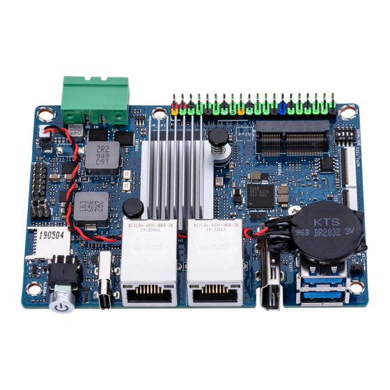
Page 13: Motherboard Layout
Motherboard layout Single Board Computer... - Page 14 Layout contents Page DC-in Power connector GPIO header Boot Mode switch M.2 Wi-Fi slot MIPI CSI connector Micro SD card slot I2C header SPI TPM header RTC Battery connector Reset button MIPI DSI connector IO Board-to-Board connector Single Board Computer...
-
Page 15: Onboard Button And Switches
Onboard button and switches Boot Mode switch The Boot Mode switch allows you to configure between different boot modes and the location to boot from. Please refer to the table below for the different boot modes. Boot Mode Boot type Serial Downloader Internal Boot (default) Boot Mode... -
Page 16: Reset Button
Reset button Press the Reset button to reboot the system. Single Board Computer... -
Page 17: Internal Connectors
Internal connectors DC-in Power connector The DC-in Power connector is for DC power input. Using a compatible power cable, connect the Pico-ITX board to a power supply. Connector type POWER CON 2P R/A Single Board Computer... -
Page 18: Gpio Header
GPIO header This 40-pin GPIO (General-purpose Input/Output) header can be designated (in software) as an input or output pin and is used for a wide range of purposes. Of the 40 pins, 28 are GPIO pins (shared with SPI/UART/I2C pins). M.2 Wi-Fi slot The M.2 Wi-Fi slot allows you to install an M.2 Wi-Fi module (E-key, type 2230). -
Page 19: Mipi Csi Connector
MIPI CSI connector This connector connects to camera module via a four lane MIPI CSI-2 cable. This connector supports up to 80Mbps connection speed - 1.5Gbps per lane, providing 4K@30fps capability for the 4 lanes. IMPORTANT! Ensure the cable for MIPI CSI is connected in the correct orientation with the gold fingers facing towards the top of the motherboard. -
Page 20: Micro Sd Card Slot
Micro SD Card slot The Micro SD Card slot allows you to install a Micro SD card. NOTE: The Micro SD card is purchased separately. C header The I C (Inter-Integrated Circuit) connector allows you to connect an I compatible IoT security module. Connector type Header 2x3p, K6, 2.0mm pitch Single Board Computer... -
Page 21: Spi Tpm Header
SPI TPM header The SPI TPM header supports a Trusted Platform Module (TPM) system, which can securely store keys, digital certificates, passwords, and data. A TPM system also helps enhance network security, protects digital identities, and ensures platform integrity. Connector type Header 2x7p,K14, 2.0mm pitch RTC Battery connector The RTC Battery connector allows you to connect the lithium CMOS... -
Page 22: Mipi Dsi Connector
MIPI DSI connector This connector connects to a display module via a four lane MIPI DSI cable. This connector supports up to 1920 x 1080 @ 60 Hz connection speed. Single Board Computer... -
Page 23: 10. Io Board-To-Board Connector
10. IO Board-to-Board connector The IO Board-to-Board connector allows you to connect the Pico-ITX motherboard and secondary I/O board. Single Board Computer... -
Page 24: I/O Connectors
I/O connectors Front panel Front panel connectors Power button The power button allows you to turn the Single Board Computer on or off. You can use the power button to put your Single Board Computer to sleep mode or press it for ten (10) seconds to force shutdown your Single Board Computer. - Page 25 Front panel connectors Reset button The button allows you to reset the Single Board Computer.
-
Page 27: Chapter 3: Upgrading Your Single Board Computer
Upgrading your Single Board Computer... -
Page 28: Installing An Micro Sd Card
IMPORTANT! • Ensure that your hands are dry before proceeding with the rest of the installation process. Before installing any of the features in this guide, use a grounded wrist strap or touch a safely grounded object or metal object to avoid damaging them due to static electricity. -
Page 29: Installing The Wireless Card
Installing the wireless card Remove the M.2 stand screw. Align and insert the wireless card into its slot on the motherboard, then gently push down the wireless card on top of the screw hole and fasten it using the previously removed stand screw. (optional) Connect the antennas to your wireless card. - Page 30 Single Board Computer...
-
Page 31: Appendix
Appendix... -
Page 32: Safety Information
Safety information Your Edge Computer is designed and tested to meet the latest standards of safety for information technology equipment. However, to ensure your safety, it is important that you read the following safety instructions. Setting up your system • Read and follow all instructions in the documentation before you operate your system. -
Page 33: Care During Use
Care during use • Do not walk on the power cord or allow anything to rest on it. • Do not spill water or any other liquids on your system. • When the system is turned off, a small amount of electrical current still flows. -
Page 34: Regulatory Notices
Regulatory notices COATING NOTICE IMPORTANT! To provide electrical insulation and maintain electrical safety, a coating is applied to insulate the device except on the areas where the I/O ports are located. Federal Communications Commission Statement This device complies with Part 15 of the FCC Rules. Operation is subject to the following two conditions: •... - Page 35 RF exposure warning This equipment must be installed and operated in accordance with provided instructions and the antenna(s) used for this transmitter must be installed to provide a separation distance of at least 20 cm from all persons and must not be co-located or operating in conjunction with any other antenna or transmitter.
- Page 36 Compliance Statement of Innovation, Science and Economic Development Canada (ISED) This device complies with Innovation, Science and Economic Development Canada licence exempt RSS standard(s). Operation is subject to the following two conditions: (1) this device may not cause interference, and (2) this device must accept any interference, including interference that may cause undesired operation of the device.
- Page 37 VCCI: Japan Compliance Statement Class A ITE Japan RF Equipment Statement 屋外での使用について 本製品は、 5GHz帯域での通信に対応しています。 電波法の定めにより 5.2GHz、 5.3GHz帯域の電波は屋外で使 用が禁じられています。 法律および規制遵守 本製品は電波法及びこれに基づく命令の定めるところに従い使用してくだ さい。 日本国外では、 その国の法律ま たは規制により、 本製品の使用ができないことがあります。 このような国で は、 本製品を運用した結果、 罰せられ ることがありますが、 当社は一切責任を負いかねますのでご了承ください。 Single Board Computer...
- Page 38 ASUS products sold in Vietnam, on or after September 23, 2011,meet the requirements of the Vietnam Circular 30/2011/TT-BCT. Các sản phẩm ASUS bán tại Việt Nam, vào ngày 23 tháng 9 năm2011 trở về sau, đều phải đáp ứng các yêu cầu của Thông tư 30/2011/TT-BCT của Việt Nam.
- Page 39 All ASUS products with the ENERGY STAR logo comply with the ENERGY STAR standard, and the power management feature is enabled by default. The monitor is automatically set to sleep within 10 minutes of user inactivity;...
- Page 40 Manufacturer ASUSTeK Computer Inc. Tel: +886-2-2894-3447 Address: 1F., No. 15, Lide Rd., Beitou Dist., Taipei City 112, Taiwan Authorised ASUSTeK Computer GmbH representative in Address: Harkortstrasse 21-23, 40880 Ratingen, Europe Germany Single Board Computer...
-
Page 41: Asus Contact Information
+1-510-608-4555 Web site http://www.asus.com/us/ Technical Support Support fax +1-812-284-0883 Telephone +1-812-282-2787 Online support https://www.asus.com/support/Product/ContactUs/Services/ questionform/?lang=en-us ASUS COMPUTER GmbH (Germany and Austria) Address Harkortstrasse 21-23, 40880 Ratingen, Germany Web site https://www.asus.com/de Online contact https://www.asus.com/support/Product/ContactUs/Services/ questionform/?lang=de-de Technical Support Telephone (DE) +49-2102-5789557 Telephone (AT) - Page 42 Single Board Computer...
Need help?
Do you have a question about the IMX8P-IM-A and is the answer not in the manual?
Questions and answers