Sony VPL-FHZ700L Service Manual
Remote commander rm-pj27
Hide thumbs
Also See for VPL-FHZ700L:
- Quick reference manual (148 pages) ,
- Operating instructions manual (63 pages) ,
- Manual (12 pages)
Table of Contents
Advertisement
Quick Links
Advertisement
Table of Contents

Related Manuals for Sony VPL-FHZ700L


Summary of Contents for Sony VPL-FHZ700L
- Page 1 DATA PROJECTOR VPL-FHZ700L REMOTE COMMANDER RM-PJ27 SERVICE MANUAL 1st Edition...
- Page 2 Unterbrecher einzufügen, Dette utstyret kan kobles til et IT-strømfordelingssystem. oder das Netzkabel muß mit einer in der Nähe des Geräts befi ndlichen, leicht zugänglichen Wandsteckdose verbunden werden, damit sich bei einer Funktionsstörung die Stromversorgung zum Gerät jederzeit unterbrechen läßt. VPL-FHZ700L...
- Page 3 警告ラベルは上部パネルに貼られています。 本機は,CLASS 2 LASER PRODUCT に分類されます。CLASS 2 LASER PRODUCT ラベルは,本機左側面のベースユニット に貼られています。 Denna etikett är placerad på dataprojektorns övre panel. Denna dataprojektor är klassifi cerad som en LASERPRODUKT AV KLASS 2. Etiketten LASERPRODUKT AV KLASS 2 fi nns på dataprojektorns vänstra sida. 1 (P) VPL-FHZ700L...
- Page 4 Batterien nur durch den vom Hersteller empfohlenen Kasser batteriet i henhold til gjeldende avfallsregler. oder einen gleichwertigen Typ ersetzen. Wenn Sie die Batterie entsorgen, müssen Sie die Gesetze der jeweiligen Region und des jeweiligen Landes befolgen. 注意 注意 如果更换的电池不正确,就会有爆炸的危险。 只更换同一类型或制造商推荐的电池型号。 处理电池时,必须遵守相关地区或国家的法律。 2 (P) VPL-FHZ700L...
-
Page 5: Table Of Contents
Prism (F) Assembly .........2-1 (E) 1-6-21. Lens Shift Unit/Prism (F) Assembly/ 2-2-3. B Board ............2-2 (E) SB Board ............1-33 (E) 2-2-4. QB Board ............2-2 (E) 1-6-22. Out-pre-polarizer (R)/(G)/(B) and 2-2-5. Laser Source Unit (F) ........2-2 (E) Out-polarizer (R)/(G)/(B) ......1-34 (E) 1 (E) VPL-FHZ700L... - Page 6 Adjustment Item Initialize Data ......2-25 (E) Spare Parts 3-1. Notes on Repair Parts ............3-1 3-2. Exploded Views ............... 3-2 3-2-1. VPL-FHZ700L ............3-2 3-2-2. Lens Adapter ............3-20 3-2-3. Option Lens............3-21 3-3. Packing Materials & Supplied Accessories ..............3-24...
-
Page 7: Manual Structure
Manual Structure Purpose of this manual This manual is the Service Manual of the Data Projector VPL-FHZ700L. This manual describes the information on the premise of providing the block level service (such as service overview, adjustment, spare parts and block diagrams). -
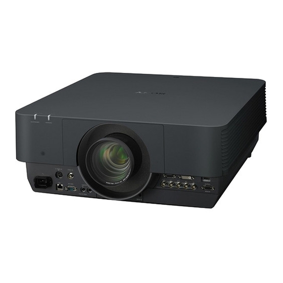
Page 9: Service Overview
. In order to avoid inappropriate use of the laser diode, do not disassemble the laser source unit (F). . When performing the adjustment that requires turning the power of this unit off and on, be sure to perform the operation with the top cover assembly attached. 1-2. Appearance Figure 1-1 (E) VPL-FHZ700L... -
Page 10: Precaution For Transport
Lens ( 1) Screws (with stoppers) B Hooks Lens door Screws (with stoppers) B Screws (with stoppers) A 1: The lens in the illustration is VPLL-Z4019. 4. Attach the front cover (supplied with this unit). Front cover 1-2 (E) VPL-FHZ700L... -
Page 11: Board Location
1-4. Board Location VPL-FHZ700L LD A board (switching regulator) NR board C board GC board LD B board (switching regulator) M board HA board HB board G board (power unit) NF board F board (EMI filter) QC board T board... -
Page 12: Tightening Torque
1.20 ?0.18 N.m . SP 4-4O UNC: 0.80 ?0.12 N.m . Screw (with stopper): 0.80 ?0.12 N.m When using the torque driver with the notation of cN.m, interpret it as follows. Example: 0.8 N.m = 80 cN.m 1-4 (E) VPL-FHZ700L... -
Page 13: Disassembly
[RESET] button on the remote controller to move the lens shift unit to the specifi ed position. When the lens shift unit is moved to the center position, the screws can be removed. V base Lens shift unit 1-5 (E) VPL-FHZ700L... - Page 14 1-6-1. Filter Holder Assembly 1-6-2. Top Cover Assembly/HA Board 1-6-7. DC Fan (For PS Converter) 1-6-6. C Board/M Board 1-6-5. B Board/QA Board 1-6-19. PS Converter 1-6-4. T Board/V Board 1-6 (E) VPL-FHZ700L...
- Page 15 1-6-10. Laser Source Unit (F) 1-6-3. GC Board/DC Fan (For the Exhaust of (R)/(G)/(B) Assembly Laser Source Unit (F)) 1-6-11. NR Board 1-6-13. Optical Unit (F) Assembly 1-6-22. Out-polarizer (R)/(G)/(B) and 1-6-21. Lens Shift Unit/ Out-pre-polarizer (R)/(G)/(B) Prism (F) Assembly/SB Board 1-7 (E) VPL-FHZ700L...
- Page 16 1-6-18. DC Fan (For the Air Antake of Laser Source Unit (F)) G PANEL / B PANEL) 1-6-12. QB Board/QC Board 1-6-16. F Board (EMI Filter) 1-6-9. G Board (Power Unit) / HB Board / NF Board / DC Fan (For Power Supply) 1-8 (E) VPL-FHZ700L...
-
Page 17: Filter Holder Assembly
3. 1 Remove the filter door in the direction of the arrow A. 3 Cable tie 2 Strap 8 Four hooks 9 Electrostatic filter 5 Filter holder assembly 6 Four hooks 7 Electrostatic filter 1-9 (E) VPL-FHZ700L... -
Page 18: Top Cover Assembly/Ha Board
7 Top cover assembly HA board CN50 5 Screw (PSW 3 6 Harness 2 Two hooks 4 Ten screws. (BVTP3 1 Loosen the four screws (with stoppers). 3 Remove the lens door in the direction of the arrow. 1-10 (E) VPL-FHZ700L... - Page 19 @= HA button @\ Reflection plate (TOP) (PWHTP3 !. Lever B !, Helical torsion spring !' Lever A @- Button (ARROW) !; Helical torsion spring !\ Cover plate @/ HA board !] Screw @[ Cushion F (PWHTP3 1-11 (E) VPL-FHZ700L...
-
Page 20: Gc Board/Dc Fan (For The Exhaust Of Laser Source Unit (F))
4 Door L fan cover (upper) Remove the hook, then pull upward. 3 Hook 6 Door assembly 5 Two screws 8 Two harnesses 9 Two screws (PSW3 1 Harness CN2801 CN2803 CN2802 0 GC board 7 Flexible flat cable CN107 M board 1-12 (E) VPL-FHZ700L... - Page 21 When attaching the DC fans, attach them with the label side oriented as shown in the illustration. !] Lamp door (FL-U) Label side !- Four screws (BVTP3 Label side ![ Two screws (BVTP3 !, Four screws (PSW4 !; Relay connectors 1-13 (E) VPL-FHZ700L...
-
Page 22: T Board/V Board
1-6-4. T Board/V Board 0 Screw !- T board (PSW3 4 Four screws 9 Harness (BVTP3 1 Two screws (BVTP3 CN90 8 V board 5 Chassis (filter) 7 Two screws (PSW3 6 Harness 3 Sub-chassis (filter) 2 Screw (BVTP3 1-14 (E) VPL-FHZ700L... -
Page 23: B Board/Qa Board
fi ne-wire coaxial cable. B board (side B) CN102(To QC) CN901(To QB) CN100(To QB) CN800(To HB) CN500(To G) CN1688(To TH_PNL) CN501(To G) CN1689(To SB) CN802(To GC) CN101(To M) CN907(To C) 1-15 (E) VPL-FHZ700L... - Page 24 1 Connector sheet R 2 Two connector screws 6 Two screws Be sure to secure the harness ( 1) with the clamper to prevent it from 5 Four screws 4 Two connector screws being cut by the top cover. (BVTP3 1-16 (E) VPL-FHZ700L...
-
Page 25: C Board/M Board
(To Fan) CN114 CN112 (To fan) (To V board/T board) CN101 CN102 (To G board) (To fan) CN111 CN304 (To lens shift unit) (To laser source unit (F)) CN300 (To lens shift unit) CN100 (To B board) 1-17 (E) VPL-FHZ700L... - Page 26 !; C board holder When disconnecting the fine-wire coaxial cable, remove it in the direction of the arrow C while pushing the two hooks in the direction of the arrows A and B. !- Fine-wire coaxial cable 1-18 (E) VPL-FHZ700L...
-
Page 27: Dc Fan (For Ps Converter)
4 Four fan cushions (lamp) 5 DC fan 6 PS converter function When attaching the DC fan, attach it with the label side oriented as shown in the illustration. 1 Relay connectors Label side 7 Four fan cushions (lamp) 1-19 (E) VPL-FHZ700L... -
Page 28: Dc Fan (For Ld B)/Switching Regulator (Ld B)
![ Four hooks !; LDA case (B) 8 Screw 2 Two harnesses (PSW3 1 Harness @/ DC fan 4 Relay connector !. B duct (B) !, Two screws 0 Three screws (PSW3 6 Harness (PSW3 !- LDB shield plate 1-20 (E) VPL-FHZ700L... -
Page 29: G Board (Power Unit)/Hb Board/Nf Board/Dc Fan (For Power Supply)
8 G-FL shield plate (B) 9 Harness 0 Four screws (PSW3 Label side !- G board (power unit) 7 Five screws (PSW3 1 Two screws (PSW3 2 HB board 3 Screw != G-FL shield plate assembly (PSW3 4 NF board 1-21 (E) VPL-FHZ700L... -
Page 30: Laser Source Unit (F)
Be careful not to hit the laser source unit (F). 5 Hook 7 Harness 3 Flexible flat cable != Laser source 5 Hook unit (F) 1 Two screws (PSW3 Remove the hook, 8 Harness then pull upward. 2 Cover (laser unit) 1-22 (E) VPL-FHZ700L... -
Page 31: Nr Board
1-6-11. NR Board 2 Hook 3 Remove the NR board in the direction of the arrow. 1 Harness 1-23 (E) VPL-FHZ700L... -
Page 32: Qb Board/Qc Board
!] QB board CN1006 != Harness CN1002 CN1001 CN1005 1 Screw (PSW4 2 Ground terminal 6 Connector sheet L 5 AC inlet 4 Plug holder A 3 Two screws 7 Two screws 0 Two connector screws (BVTP3 1-24 (E) VPL-FHZ700L... -
Page 33: Optical Unit (F) Assembly
1-6-13. Optical Unit (F) Assembly When replacing the optical unit (F) assembly, perform the procedure in Section 2-2-1. 2 Four screws (PSW4 4 Optical unit (F) assembly 3 Loosen the two screws (with stoppers). B board 1 Harness CN1688 1-25 (E) VPL-FHZ700L... -
Page 34: Dc Fan (For The Air Intake Of R Panel/G Panel/B Panel)
Route the harness of each DC fan as shown in the illustration. Hook Notch DC fan Harness of DC fan Prism duct (bottom) Hook Notch Hook Harness of DC fan DC fan DC fan Harness of DC fan Front side Notch Hook 1-26 (E) VPL-FHZ700L... -
Page 35: Qm Board
1-6-15. QM Board 4 Five screws CN1803 (BVTP3 1 Two harnesses 7 QM board 5 Connector panel R CN1805 CN1803 2 Harness 6 Two screws (PSW3 3 Screw (PSW3 1-27 (E) VPL-FHZ700L... -
Page 36: F Board (Emi Filter)
1-6-16. F Board (EMI Filter) 2 Harness 1 Harness 3 Four screws (PSW3 4 F board (EMI filter) 1-28 (E) VPL-FHZ700L... -
Page 37: Ld A Board (Switching Regulator)
8 Five screws 7 Three harnesses (PSW3 6 Harness 9 LD A board (switching regulator) 0 Insulating sheet LD A 1 Two screws (PSW3 2 Two screws (PSW3 3 LD A shield plate 4 Four screws (PSW3 1-29 (E) VPL-FHZ700L... -
Page 38: Dc Fan (For The Air Intake Of Laser Source Unit (F))
2 Two screws (PSW3 6 Screw (PSW3 !- Laser duct ![ DC fan 0 Four screws (PSW3 Attach the DC fan with the label side oriented as shown in the illustration. != Two screws Label side (PSW4 1-30 (E) VPL-FHZ700L... -
Page 39: Ps Converter
When replacing the PS converter, perform the procedure in Section 2-4. 1 Four screws (PSW3 2 Cover (EF) Marking 3 PS converter Attach the PS converter so that the marking on the PS converter is located as shown in the illustration. 1-31 (E) VPL-FHZ700L... -
Page 40: In-Polarizer (R)/(G)/(B) Assembly
When attaching the in-polarizer (R)/(G)/(B) assembly, secure them so that each screw is located in the center of the elongate hole. Adjustment knob In-polarizer (G) assembly Elongate hole Screw (P2.6 In-polarizer (B) In-polarizer (R) assembly assembly Elongate hole Elongate hole Screw (P2.6 Screw (P2.6 Adjustment knob Adjustment knob 1-32 (E) VPL-FHZ700L... -
Page 41: Lens Shift Unit/Prism (F) Assembly/Sb Board
4 Three screws 6 Three screws (PSW3 (PSW3 7 Adjustment lens adaptor 5 Prism (F) assembly 3 Two harnesses 1 Four screws (PSW4 2 Lens shift unit 8 Harness !/ Two screws (PSW3 !- SB board 9 Screw (PSW3 1-33 (E) VPL-FHZ700L... -
Page 42: Out-Pre-Polarizer (R)/(G)/(B) And Out-Polarizer (R)/(G)/(B)
Attach the out-polarizer and out-pre-polarizer so that each marking is located as shown in the illustration. 4 Out-pre-polarizer (G) Top view of prism (F) assembly Marking 7 Out-polarizer (G) 3 Out-pre-polarizer (R) Marking 6 Out-polarizer (R) 5 Out-pre-polarizer (B) 8 Out-polarizer (B) Marking Front side 1-34 (E) VPL-FHZ700L... -
Page 43: Installation/Removal Of Optional Lens
2. Press the [SHIFT] or [LENS|SHIFT] button on this unit or the remote commander, then press the [RESET] button on the remote controller. The lens shift unit returns to the position (initial setting) as shown in the illustration. V base Lens shift unit 1-35 (E) VPL-FHZ700L... -
Page 44: Removal Of Back Correction Glass Assembly
When removing the back correction glass assembly, rotate it in the direction of the arrow A so that the mark of the back correction glass assembly is aligned with the mark of the lens adjustment adaptor. Lens adjustment adaptor Marks Back correction glass assembly 1-36 (E) VPL-FHZ700L... -
Page 45: Installation Of Lens Adaptor
When attaching the optional lens VPLL-ZM42, the lens adaptor PK-F500LA2 is required. 1. Insert the lens into the lens adaptor. PK-F500LA2 2. Secure the lens with the four screws. Screws Screws Move the lens until there is no gap. 1-37 (E) VPL-FHZ700L... -
Page 46: Installation/Removal Of Optional Lens
5. Attach the lens door in the reverse order of step 1. Removal 1. Remove the lens door. (Refer to steps 1 to 3 in Section 1-6-2.) 2. Loosen the four screws (with stoppers), then pull out the lens straight. Screws (with stoppers) Screws (with stoppers) 1-38 (E) VPL-FHZ700L... -
Page 47: Focus Adjustment Of Peripheral Area
(Refer to “If the peripheral area is out of focus”.) 5. Check that the screen center portion is in focus. 6. If it is out of focus, repeat steps 3 and 4. 1-39 (E) VPL-FHZ700L... - Page 48 In such a case, perform the adjustment by changing the number of spacers inside of the adaptor. 1. Remove the optional lens VPLL-Z4007 from this unit. (Refer to Section 1-7-5.) 2. Loosen the six screws, then remove the adaptor. Screws Adaptor Lens 1-40 (E) VPL-FHZ700L...
- Page 49 The number of spacers varies depending on the optional lens. If the focus moves close to Just Focus when you rotate the peripheral focus ring in the clockwise direction as far as it will go, add a spacer. Spacer 1-41 (E) VPL-FHZ700L...
- Page 50 If the focus moves away from Just Focus when you rotate the peripheral focus ring in the clockwise direction as far as it will go, remove a spacer. Spacer 5. Secure the spacer with the two screws. Screws 1-42 (E) VPL-FHZ700L...
- Page 51 Screws Adaptor Connector portion Spring Lens 7. Attach the lens to this unit. 8. Perform steps 1 to 4 in “Focus Adjustment of Peripheral Area”. 1-43 (E) VPL-FHZ700L...
-
Page 52: Cleaning
If you touch the glass portion, the polarized layer may be peeled off, causing an optical failure. Required items Air dust spray, blower, drinking water, tissue paper Preparation Remove the in-polarizer (R)/(G)/(B) assembly. (Refer to Section 1-6-20.) 1-44 (E) VPL-FHZ700L... - Page 53 Attach the in-polarizer (R)/(G)/(B) assemblies so that each screw is located in the center of the elon- gate hole. in-polarizer (G) assembly The screw is located in the center of the elongate hole. Optical unit (F) assembly (top view) 1-45 (E) VPL-FHZ700L...
-
Page 54: Cleaning Of Illumination System Optical Parts
3. Wipe off the dust and dirt adhered to the removed optical parts on both sides with the tissue paper dampened with drinking water. Four screws (PSW3 Cover (RGB) R channel mirror Markings An instruction marking G reflection dichroic mirror is indicated on the back side. B transmission dichroic mirror 1-46 (E) VPL-FHZ700L... - Page 55 B transmission dichroic mirror Never touch the B channel mirror. 6. To install, reverse the removal procedure. When attaching the B transmission dichroic mirror, G refl ection dichroic mirror and R channel mirror, pay attention to the marking position. 1-47 (E) VPL-FHZ700L...
-
Page 56: Cleaning Of Ps Converter, First Fly-Eye Lens And Second Fly-Eye Lens
4. Blow off the dust and dirt adhered to the fi rst fl y-eye lens and the second fl y-eye lens. 5. To install, reverse the removal procedure. When attaching the PS converter, pay attention to the marking position. 1-48 (E) VPL-FHZ700L... -
Page 57: Cleaning Of Total Reflection Mirror 3
3. Wipe off the dust and dirt adhered to the total refl ection mirror 3 on both sides with the tissue paper dampened with drinking water. 4. To install, reverse the removal procedure. When attaching the total refl ection mirror 3, pay attention to the marking position. 1-49 (E) VPL-FHZ700L... -
Page 58: Cleaning Of Prism (F) Assembly
Remove the optical unit (F) assembly. (Refer to Section 1-6-13.) Procedure 1. Blow off the dust and dirt adhered to the portions A (liquid crystal plate and out-polarizer) using the air dust spray or blower. Portions A Prism (F) assembly (top view) 1-50 (E) VPL-FHZ700L... -
Page 59: Service Mode (Network Volume)
You are prompted to enter a user name and password. Enter them as follows: User name: service Password: (Lower-case model name) Example: vpl-fhz700l When moving from the service mode to other pages and entering the service mode again, close a Web browser once and start the Web browser again. - Page 60 . Network Update Bridge: Used for serial-to-network conversion. . Null-modem emulator: Used for virtual port creation. For obtaining each application, please contact your local Sony Sales Offi ce/Service Center. (1) Install Network Update Bridge. 1) Copy Network Update Bridge.exe below C:\Projector\Network Update Bridge.
- Page 61 When Main/Sub is updated; Pull out and insert the AC cord of a projector after Network Update Bridge is closed every time each updating is completed. Return to step 1 for updating when continuing updating. 1-53 (E) VPL-FHZ700L...
-
Page 62: Event Trace Function
Serial number . Location: Installation site (Blanked when Location is not set.) ROM Ver. . Main ROM Version: Version of Main ROM . Sub ROM Version: Version of Sub ROM . Ext ROM Version: Version of Ext ROM 1-54 (E) VPL-FHZ700L... - Page 63 SIGNAL WARNING FREQUENCY OVER: Input signal frequency warning SIGNAL WARNING SIGNAL SETTING MISTAKE: Input signal type warning FILTER CLEANING: Filter cleaning FILTER REPLACE: Filter replacement SHOCK FAILURE: Shock error BRIGHTNESS FAILURE: Brightness error WHEEL FAILURE: Wheel error 1-55 (E) VPL-FHZ700L...
- Page 64 Requested action not taken: mailbox name not The name of a mailbox is improper, so data allowed was not delivered. Transaction failed Processing failed. (Continue) 1-56 (E) VPL-FHZ700L...
-
Page 65: Setup Function
Web password on the password setting screen again. 1-10. Web Password Change If you forget your Web password, enter the Service mode (Section 1-7), and then set a new password in [Password] in [Setup] in the Web screen. 1-57 (E) VPL-FHZ700L... -
Page 66: Location Information Of The Labels
(center) and the front of the Lens L’ Type cabinet VPLL-4008 57.8 (2 VPLL-ZM42 40.1 (1 VPLL-Z4007 15.0 ( Front of the cabinet VPLL-Z4011 75.5 (2 Front of the lens VPLL-Z4015 47.8 (1 VPLL-Z4019 26.7 (1 VPLL-Z4025 55.4 (2 VPLL-Z4045 53.0 (2 1-58 (E) VPL-FHZ700L... -
Page 67: Indicator Display
The connectors to temperature sensor boards (U and V boards) are not connected properly. Light source error The light source does not light normally. Lens detect error The lens is not installed. Drop error The drop is detected. 1-59 (E) VPL-FHZ700L... -
Page 68: Circuit Description
The M board drives all fans and power lenses. The M board detects whether a top cover assembly is installed. GC board The GC board drives the wheel of a fl uorescent material and detects the rotation error of the wheel. 1-60 (E) VPL-FHZ700L... -
Page 69: Sensor Boards
The LA board mounts a laser diode and supplies power. The LA board mounts the temperature sensor of the laser diode. LB board The LB board mounts a laser diode and supplies power. The LB board mounts the temperature sensor of the laser diode. 1-61 (E) VPL-FHZ700L... -
Page 70: Lead-Free Solder
. The ordinary soldering iron can be used but the iron tip has to be applied to the solder joint for a slightly longer time. The printed pattern (copper foil) may peel away if the heated tip is applied for too long, so be careful. 1-62 (E) VPL-FHZ700L... -
Page 71: Adjustments
2. Write the Opt Unit data supplied with the optical unit (F) assembly using Quick Access2. (Refer to Section 2-6-5.) 3. Perform the laser luminance and luminance sensor adjustment. (Refer to Section 2-4.) 4. Check the white balance state, and perform the adjustment as required. (Refer to Section 2-3-3.) 2-1 (E) VPL-FHZ700L... -
Page 72: B Board
1. Perform the Ext (Network) reset. (Refer to Section 2-5-5.) 2-2-5. Laser Source Unit (F) When replacing the laser source unit (F) assembly, perform the following procedure. 1. Perform the laser luminance and luminance sensor adjustment. (Refer to Section 2-4.) 2-2 (E) VPL-FHZ700L... -
Page 73: Electrical Adjustment
6 seconds since the last button is pressed, and perform the button operations again. 4. Select “Model Name Display”. To exit the Model Name Display mode, perform step 3. “Demonstration mode screen” is displayed. Select “Off”. 2-3 (E) VPL-FHZ700L... -
Page 74: Com Adjustment
(7) Repeat steps (3) to (6) until the chromaticity (x ?0.002, y ?0.002) with reference to the target chromaticity (x, (8) Select the menus in following order: Device → Memory Save. Select [YES], and press the [ENTER] button to save. 2-4 (E) VPL-FHZ700L... - Page 75 (10) Repeat steps (6) to (9) until the chromaticity (x ?0.002, y ?0.002) with reference to the target chro- maticity (x, y). (11) Select the menus in following order: Device → Memory Save. Select [YES], and press the [ENTER] button to save. 2-5 (E) VPL-FHZ700L...
- Page 76 (9) Repeat steps (5) to (8) until the chromaticity (x ?0.002, y ?0.002) with reference to the target chro- maticity (x, y). (10) Select the menus in following order: Device → Memory Save. Select [YES], and press the [ENTER] button to save. 2-6 (E) VPL-FHZ700L...
-
Page 77: Adjustment Of Laser Luminance And Luminance Sensor
. Bandpass filter (product code: #86-350) made by Edmund Optics or the equivalent . Personal computer (PC) . RS-232C cross cable . Brightness Adjustment Tool software For obtaining the software, please contact your local Sony Sales Office/Service Center. 2-7 (E) VPL-FHZ700L... -
Page 78: Setting Of This Unit And Power Meter Sensor
Create the aperture with the following specifications. . Φ7.0 mm . t = 0.3 mm or less . Color: Black . Metal (aluminum, etc.) 7. Set the laser power sensor as follows. . Filter: . Range: 300 mW . Wavelength: 445 nm 2-8 (E) VPL-FHZ700L... -
Page 79: Preparation
7. Place a check mark in Port Open and check that the communication can be performed. (Select the name of compatible model.) In case that the communication cannot be performed, check the connection of PC. If the problem persists, restart the Brightness Adjustment Tool software. 2-9 (E) VPL-FHZ700L... - Page 80 23. Check that the laser power sensor is installed in front of the lens. (Refer to Section 2-4-2.) Check that the shadow of sensor at that time is positioned in the center of the projected image. Projected image from the projector Shadow of sensor 2-10 (E) VPL-FHZ700L...
-
Page 81: Electronic Volume Adjustment
When LAMP_MAX_DUTY is lowered, the amount of light tends to increase due to the decrease in the LD temperature. Therefore, take time for the adjustment. 2-4-6. Luminance Constant Mode Adjustment 1. Read the value of SENSOR_OUT_ADC. 2. Set this value to LAMP_MAX_BRT. 2-11 (E) VPL-FHZ700L... -
Page 82: Luminance Sensor Adjustment
Find a line formula based on the two points, and obtain the DAC value at the point of the electric power threshold limit value. Value to be obtained ROBmax ROB30 P_ROB30 P_ROBmax Electric power threshold limit value 2-12 (E) VPL-FHZ700L... -
Page 83: Device Save, Adjustment Items Check And All Reset
3. Set the switch (S700) on the B board to the lower side, then attach the USB sheet. (Refer to step 2 in Section 2-4-3.) 4. Attach the filter door to this unit. (Refer to Section 1-6-1.) 2-13 (E) VPL-FHZ700L... -
Page 84: Software Update
. Anem Reset Tool: Reset tool for Ext (Network) module setting . For obtaining the each application and version upgrade file, contact your local Sony Sales Office/ Service Center. . For Ext (Network) updating PC, the installation of the softwares below is required. - Page 85 When updating Ext (network) of BKM-PJ10, set the LAN Setting to “via HDBaseT”. 3. Install each application to PC. 4. Disconnect the power cord of this unit. 5. Connect this unit with PC by RS-232C or USB-RS-232C dual, referring to the connection figure. 2-15 (E) VPL-FHZ700L...
-
Page 86: Main (Scan Converter)
2-5-2. Main (Scan Converter) 1. Copy the files to be written into the same folder of application file FlashUpgrader.exe. For files to be written, please contact your local Sony Sales Office/Service Center. 2. Double-click FlashUpgrader.exe to start the application. Application name: Pixelworks ImageProcessor SDK FlashUpgrader/SONY Custom File name: FlashUpgrader.exe... -
Page 87: Sub
1. Copy the three files rh1vXXXXX.dli, 5212.inf, and rh1vXXXXX.mot into the same folder of appli- cation file Flash.exe. XXXXX means version number. 2. Double-click Flash.exe to start the application. Application name: Sub Flash Upgrader for Sony Projector File name: Flash.exe 3. Check rh1vXXXXX.dli, 5212.inf, rh1vXXXXX.mot are selected in download information file, MCU Type setting, and ROM File Name respectively. -
Page 88: Ext (Network)
For COM*, enter the serial port number used for connecting PC. 5. Check that “Completed!!” is displayed. When “Failed” is displayed, disconnect the power cord of this unit, then perform from step 1 again. 6. Disconnect the power cord. Example screen of Ext reset via COM1 2-18 (E) VPL-FHZ700L... -
Page 89: Quick Access2
13. Click the [OK] button. The saving starts. Completed is displayed after completed. 14. Press the [I/O] button and set this unit to standby state. 15. Disconnect the power cord. 16. Click the [Complete] button. 2-19 (E) VPL-FHZ700L... -
Page 90: Saving Of Ddc Data
The window displaying the model name of this unit, serial number, and the file path of the destination of the obtained data to save is displayed. 13. Click the [OK] button. The saving starts. Completed is displayed after completed. 14. Disconnect the power cord. 15. Click the [Complete] button. 2-20 (E) VPL-FHZ700L... -
Page 91: Saving Of Nvm Data
After completed, The massage “Verify Success! Reading Model Name, Serial Number, NVM Map Version and NVM Data Version is successful.” is displayed. 15. Click the [OK] button. Completed is displayed. 16. Disconnect the power cord. 17. Click the [Complete] button. 2-21 (E) VPL-FHZ700L... -
Page 92: Writing Of B Board/Opt Unit/3Dgamma/Lookuptable/Chiral/Gcfb Data
13. Click the [OK] button. The writing starts. Completed is displayed after completed. 14. Press the [I/O] button and set this unit to standby state. 15. Disconnect the power cord. 16. Click the [Complete] button. 2-22 (E) VPL-FHZ700L... -
Page 93: Writing Of Ddc Data
The window displaying the file path, model name written in file, unit serial, serial number, and DDC ID is displayed. 13. Click the [OK] button. The writing starts. Completed is displayed after completed. 14. Disconnect the power cord. 15. Click the [Complete] button. 2-23 (E) VPL-FHZ700L... -
Page 94: Writing Of Nvm Data
After completed, The massage “Turn Off and On the AC, and then Power On to enable the new settings.” is displayed. 15. Click the [OK] button. Completed is displayed. 16. Disconnect the power cord. 17. Click the [Complete] button. 2-24 (E) VPL-FHZ700L... -
Page 95: Adjustment Item Initialize Data
Black Level Adj. Gamma Mode GRAPHICS2 GRAPHICS2 GRAPHICS1 Screen Wide Mode(SD) Wide Mode(HD) 16_9 Wide Mode(PC) FULL_1 Over Scan Adjust Signal Dot Phase Pitch Shift Function Smart APA CC Display Background BLUE Start Up Image All Reset 2-25 (E) VPL-FHZ700L... - Page 96 Constant Brightness With No Input With Static Signal Light Dimming Light Dimming 10 min. Standby Mode STANDARD Quick Reboot Direct Power On Installation Edge Blending Blending Range Bottom Left Right Zone Black Level Adj. Zone Zone1 R 2-26 (E) VPL-FHZ700L...
- Page 97 EXT ROM Version Display only Light Timer Display only Operation Timer Display only *1: “Phase, Pitch, Shift H/V” in the “Adjust Signal” menu have the initial value respectively in accordance with the input signal (PRESET MEMORY No.). 2-27 (E) VPL-FHZ700L...
- Page 98 B Offset (Component HD) SonG Threshold SonG Hysterisis Disable SonG Filter Enable HS0 Treshold HS1 Treshold HS Filter Disable Sub ADC/ R Gain G Gain B Gain R Offset G Offset B Offset (Continue to Next page) 2-28 (E) VPL-FHZ700L...
- Page 99 HPC G DATA1 HPC B DATA1 LCK ON *1: *“1” is indicated when the color temperature is set to High or Middle, and “0” is indicated when it is set to other settings. (Continue to Next page) 2-29 (E) VPL-FHZ700L...
- Page 100 High Gain R Bias R Middle Gain R Bias R Gain R Bias R Presentation Gain R Bias R Custom 1 Gain R Bias R Custom 2 Gain R Bias R Custom 3 Gain R Bias R 2-30 (E) VPL-FHZ700L...
- Page 101 B Offset (Component HD) SonG Threshold SonG Hysterisis Disable SonG Filter Enable HS0 Treshold HS1 Treshold HS Filter Disable Sub ADC/ R Gain G Gain B Gain R Offset G Offset B Offset (Continue to Next page) 2-31 (E) VPL-FHZ700L...
- Page 102 HPC G RGT0 HPC B RGT0 HPC R RGT1 HPC G RGT1 HPC B RGT1 HPC R DATA0 HPC G DATA0 HPC B DATA0 HPC R DATA1 HPC G DATA1 HPC B DATA1 LCK ON (Continue to Next page) 2-32 (E) VPL-FHZ700L...
- Page 103 High Gain R Bias R Middle Gain R Bias R Gain R Bias R Presentation Gain R Bias R Custom 1 Gain R Bias R Custom 2 Gain R Bias R Custom 3 Gain R Bias R 2-33 (E) VPL-FHZ700L...
- Page 104 B Offset (Component HD) SonG Threshold SonG Hysterisis Disable SonG Filter Enable HS0 Treshold HS1 Treshold HS Filter Disable Sub ADC/ R Gain G Gain B Gain R Offset G Offset B Offset (Continue to Next page) 2-34 (E) VPL-FHZ700L...
- Page 105 HPC G RGT0 HPC B RGT0 HPC R RGT1 HPC G RGT1 HPC B RGT1 HPC R DATA0 HPC G DATA0 HPC B DATA0 HPC R DATA1 HPC G DATA1 HPC B DATA1 LCK ON (Continue to Next page) 2-35 (E) VPL-FHZ700L...
- Page 106 High Gain R Bias R Middle Gain R Bias R Gain R Bias R Presentation Gain R Bias R Custom 1 Gain R Bias R Custom 2 Gain R Bias R Custom 3 Gain R Bias R 2-36 (E) VPL-FHZ700L...
- Page 107 B Offset (Component HD) SonG Threshold SonG Hysterisis Disable SonG Filter Enable HS0 Treshold HS1 Treshold HS Filter Disable Sub ADC/ R Gain G Gain B Gain R Offset G Offset B Offset (Continue to Next page) 2-37 (E) VPL-FHZ700L...
- Page 108 HPC G RGT0 HPC B RGT0 HPC R RGT1 HPC G RGT1 HPC B RGT1 HPC R DATA0 HPC G DATA0 HPC B DATA0 HPC R DATA1 HPC G DATA1 HPC B DATA1 LCK ON (Continue to Next page) 2-38 (E) VPL-FHZ700L...
- Page 109 High Gain R Bias R Middle Gain R Bias R Gain R Bias R Presentation Gain R Bias R Custom 1 Gain R Bias R Custom 2 Gain R Bias R Custom 3 Gain R Bias R 2-39 (E) VPL-FHZ700L...
-
Page 111: Spare Parts
Therefore, specified parts should be used in the case of な部品です。したがって,交換する時は必ず指定 replacement. の部品を使ってください。 2. Standardization of Parts 2. 部品の共通化 Some repair parts supplied by Sony differ from those ソニーから供給する補修用部品は,セットに使われて used for the unit. These are because of parts common- いるものと異なることがあります。 ality and improvement. -
Page 112: Exploded Views
Cover 3-2. Exploded Views 3-2-1. VPL-FHZ700L To HB board BVTP3 BVTP VPL-FHZ700L... - Page 113 4-539-346-01 s EMBLEM (FLB) (For White Model) 4-538-483-01 s EMBLEM (FLB) (For Black Model) 4-546-774-01 s REFLECTOR (TOP) 4-546-416-11 s LABEL, CRESTRON CONNECTED 4-548-968-11 s LABEL (NO STARE INTO MARK) 7-682-948-01 s SCREW +PSW 3X8 7-685-648-79 s SCREW +BVTP 3X12 TYPE2 IT-3 VPL-FHZ700L...
- Page 114 To V board/T board (ATMOS) CN101 To G board CN102 To Fan (R/G/B panel) CN111 CN304 To PRISM ASSY To Lens shift unit To G board To B board (Zoom/Focus) (For LAMP1, LAMP2) CN300 To Lens shift unit CN100 To B board VPL-FHZ700L...
- Page 115 1-970-481-11 s SUB HARNESS (M-GC-2P) 1-970-482-11 s SUB HARNESS (M-FAN G-4P) 1-970-484-11 s SUB HARNESS (M-FAN D/E-8P) 1-970-485-11 s SUB HARNESS (M-LA/LB-5P) 1-970-511-11 s SUB HARNESS (ASSY E) 2-650-770-21 s SLIDE, CLAMP 4-269-725-01 s SPRING (B), EARTH 7-682-948-01 s SCREW +PSW 3X8 VPL-FHZ700L...
- Page 116 Laser Source Unit To G board To M board To M board To switching regulator (LD B) To switching regulator (LD B) To M board To M board To B board BVTP BVTP BVTP VPL-FHZ700L...
- Page 117 4-539-322-11 s DOOR (FL-U), LAMP (For Black Model) 4-539-329-01 s INSULATING SHEET G FRONT 4-542-159-01 s CUSHION (FIN) 7-682-548-09 s SCREW +B 3X8 7-682-948-01 s SCREW +PSW 3X8 7-682-968-01 s SCREW +PSW 4X30 7-685-647-79 s SCREW +BVTP 3X10 TYPE2 IT-3 VPL-FHZ700L...
- Page 118 Filter BVTP BVTP BVTP BVTP To M board To M board BVTP BVTP VPL-FHZ700L...
- Page 119 4-184-560-01 s CUSHION D 4-184-561-01 s CUSHION E 4-184-563-01 s CUSHION G 4-185-057-11 s BUTTON, LOCK 4-185-059-01 s SPRING, COMPRESSION 4-258-007-01 s CUSHION (7X15) 4-539-329-01 s INSULATING SHEET G FRONT 7-682-948-01 s SCREW +PSW 3X8 7-685-648-79 s SCREW +BVTP 3X12 TYPE2 IT-3 VPL-FHZ700L...
- Page 120 To switching regulator (LD A) To F board To thermo fuse1, 2 PSW 3 To Laser source unit To B board To switching regulator (LD A) To QB board To HA board To B board To M board 3-10 VPL-FHZ700L...
- Page 121 1-970-486-11 s SUB HARNESS (B-LDB/G-12P) 2-650-770-21 s SLIDE, CLAMP 3-080-039-01 s CLAMP (FCR-15), FLAT 4-539-328-01 s INSULATING SHEET G 4-539-329-01 s INSULATING SHEET G FRONT 4-539-331-01 s SHEET LDB 7-682-948-01 s SCREW +PSW 3X8 7-682-968-01 s SCREW +PSW 4X30 3-11 VPL-FHZ700L...
- Page 122 To QB board BVTP To QB board To G board/Switching regulator (LD B) To GC board To M board To HB board To G board To C board To GC board BVTP To PRISM ASSY To SB board BVTP 3-12 VPL-FHZ700L...
- Page 123 CN1688 1-819-336-11 o HEADER ASSEMBLY FOR PWB 3P CN1689 1-820-183-11 s HEADER ASSEMBLY (PRINT PWB) 6P B Board (B side) CN801 CN903 CN102 B Board (A side) CN103 CN902 CN901 CN905 CN100 CN800 CN900 CN500 CN1688 CN501 CN1689 CN802 CN101 CN907 3-13 VPL-FHZ700L...
- Page 124 Chassis Block-1 To B board To B board To NF board BVTP BVTP To B board BVTP To F board 3-14 VPL-FHZ700L...
- Page 125 4-184-524-11 s NR, LENS 4-184-528-11 s COVER, HDSDI 4-184-529-01 s SHEET L, CONNECTOR (For White Model) 4-184-529-11 s SHEET L, CONNECTOR (For Black Model) 7-682-548-09 s SCREW +B 3X8 7-682-948-01 s SCREW +PSW 3X8 7-685-648-79 s SCREW +BVTP 3X12 TYPE2 IT-3 3-15 VPL-FHZ700L...
- Page 126 Chassis Block-2 To switching regulator (LD B) To switching regulator (LD B) To G board BVTP To G board To AC inlet PSW 3 BVTP To M board 3-16 VPL-FHZ700L...
- Page 127 (For Black Model) 4-184-560-01 s CUSHION D 4-539-330-01 s INSULATING SHEET LDA 4-545-590-01 s LABEL (FS), CAUTION 7-682-948-01 s SCREW +PSW 3X8 7-682-968-01 s SCREW +PSW 4X30 7-684-000-27 o NUT, HEXAGON (M8) TYPE2 7-685-648-79 s SCREW +BVTP 3X12 TYPE2 IT-3 3-17 VPL-FHZ700L...
- Page 128 A-2058-991-A s OUT-POLARIZER (R), S A-2058-994-A s PRISM (F) ASSY, S A-2059-410-A s MOUNTED CIRCUIT BOARD, SB A-2064-102-A s OUT-POLARIZER (F)(G), S 2-580-603-01 s SCREW, +PSW M4X16 7-621-259-25 s SCREW +P 2.6X4 7-682-948-01 s SCREW +PSW 3X8 7-682-949-01 s SCREW +PSW 3X10 3-18 VPL-FHZ700L...
- Page 129 A-2058-989-A s IN-POLARIZATION PANEL ASSY (B), S A-2058-990-A s IN-POLA PANEL ASSY (G), S A-2058-995-A s CONVERTER, P/S, S 1-787-996-11 s D.C. FAN (SIROCCO) 4-099-077-01 s CUSHION (S) 4-184-603-01 s CUSHION, PSCON FAN 7-621-259-25 s SCREW +P 2.6X4 7-682-949-01 s SCREW +PSW 3X10 3-19 VPL-FHZ700L...
-
Page 130: Lens Adapter
Lens Adapter 3-2-2. Lens Adapter PK-F500LA2 1001 1002 Part No. SP Description 1001 A-1790-164-A s PLATE LA ASSY (LA2), S 1002 2-580-593-01 s SCREW +PSW M3x8 3-20 VPL-FHZ700L... -
Page 131: Option Lens
ネジ3本 Lens マーキング レンズ 6 Lens flange レンズフランジ Be careful not to touch the spacer ring because it is thin and fragile. スペーサーリングは薄く破損しやすいので触れない Lens flange ように注意してください。 レンズフランジ 4 Motor assembly 7 Lens モーター組立 レンズ 3-21 VPL-FHZ700L... - Page 132 モーター組立 7 Lens flange レンズフランジ Lens Fixed ring レンズ 固定リング 2 Two screws ネジ2本 1 Put the marks on the lens flange and lens. レンズフランジとレンズにマークをつける。 3 Four screws ネジ4本 8 Lens レンズ 3-22 VPL-FHZ700L...
- Page 133 Option Lens 3 VPLL-Z4007 VPLL-Z4011 4-074-908-01 s CAP, LENS 4-074-908-01 s CAP, LENS VPLL-ZM42 9-885-029-37 FRONT LENS CAP (PX40) 3-23 VPL-FHZ700L...
-
Page 134: Packing Materials & Supplied Accessories
(JAPANESE, ENGLISH, FRENCH, SPANISH, GERMAN, ITALIAN, SIMPLIFIED CHINESE, RUSSIAN) 4-544-270-01 s PACK, CD-ROM MANUAL, INSTRUCTION (JAPANESE, ENGLISH, FRENCH, SPANISH, GERMAN, ITALIAN, SIMPLIFIED CHINESE, RUSSIAN) NOTICES FOR THE SOFTWARE LICENCE (JAPANESE, ENGLISH, FRENCH, SPANISH, GERMAN, ITALIAN, SIMPLIFIED CHINESE, RUSSIAN) 3-24 VPL-FHZ700L... -
Page 135: Diagrams
Section 4 Diagrams VPL-FHZ700L... -
Page 136: Block Diagrams
DRIVER IC1114 T001 IC1112 RD , RD , TD , TD ETHERNET TRANS CHG_STATUS J1100 TX0, TX1, X002 RX0, RX1, 12MHz TX_EN, MDIO, IC1110 RX_DV, MDC, X001 CONTROLLER EEPROM PWR_DOWN_INT, 50MHz IC1116 RESET_NW SDRAM IC1118 SUB13.4V, ECO3.3V FLASH ROM VPL-FHZ700L... -
Page 137: Overall
FAN J FOR R PANEL FOR G PANEL FOR B PANEL V SHIFT H SHIFT ZOOM FOCUS LASER LASER LD B POWER LASER SOURCE UNIT (F) SOURCE UNIT (F) CONVERTER UNIT SOURCE UNIT (F) Overall INTAKE EXHAUST 1 EXHAUST 2 VPL-FHZ700L... -
Page 138: Frame Wiring
FAN J FAN F FAN H2 FOR R FOR G FOR B PANEL PANEL PANEL LASER LASER LASER SOUCE UNIT (F) SOUCE UNIT (F) CONVERTER SOUCE UNIT (F) POWER LD B EXHAUST 1 EXHAUST 2 INTAKE UNIT Frame Wiring VPL-FHZ700L... - Page 140 Printed in Japan Sony Corporation VPL-FHZ700L (SY) J, E 2014. 8 32 9-878-602-01 ©2014...
Need help?
Do you have a question about the VPL-FHZ700L and is the answer not in the manual?
Questions and answers