Dell XPS 13 9310 Service Manual
Hide thumbs
Also See for XPS 13 9310:
- Setup and specifications (22 pages) ,
- Setup and specifications (23 pages)

Related Manuals for Dell XPS 13 9310


Summary of Contents for Dell XPS 13 9310
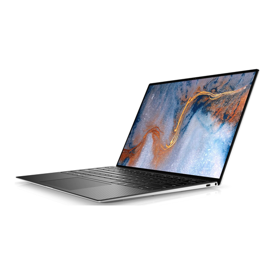
- Page 1 XPS 13 9310 Service Manual Regulatory Model: P117G Regulatory Type: P117G002 September 2020 Rev. A00...
- Page 2 A WARNING indicates a potential for property damage, personal injury, or death. © 2020 Dell Inc. or its subsidiaries. All rights reserved. Dell, EMC, and other trademarks are trademarks of Dell Inc. or its subsidiaries. Other trademarks may be trademarks of their respective owners.
-
Page 3: Table Of Contents
Transporting sensitive components..........................7 After working inside your computer..........................7 Chapter 2: Removing and installing components................8 Recommended tools................................8 Screw list....................................8 Major components of XPS 13 9310..........................9 Base cover.................................... 11 Removing the base cover............................11 Installing the base cover.............................14 Battery....................................15 Lithium-ion battery precautions.......................... - Page 4 Clearing CMOS settings..............................57 Clearing BIOS (System Setup) and System passwords...................57 Chapter 5: Troubleshooting......................58 Recovering the operating system..........................58 SupportAssist | On-board Diagnostics.........................58 System diagnostic lights..............................58 Flea power release................................59 WiFi power cycle................................60 Chapter 6: Getting help and contacting Dell.................61 Contents...
-
Page 5: Chapter 1: Working Inside Your Computer
You should only perform troubleshooting and repairs as authorized or directed by the Dell technical assistance team. Damage due to servicing that is not authorized by Dell is not covered by your warranty. See the safety instructions that is shipped with the product or at www.dell.com/regulatory_compliance. -
Page 6: Electrostatic Discharge-Esd Protection
ESD protection is an increasing concern. Due to the increased density of semiconductors used in recent Dell products, the sensitivity to static damage is now higher than in previous Dell products. For this reason, some previously approved methods of handling parts are no longer applicable. -
Page 7: Transporting Sensitive Components
It is recommended that all field service technicians use the traditional wired ESD grounding wrist strap and protective anti-static mat at all times when servicing Dell products. In addition, it is critical that technicians keep sensitive parts separate from all insulator parts while performing service and that they use anti-static bags for transporting sensitive components. -
Page 8: Chapter 2: Removing And Installing Components
Removing and installing components NOTE: The images in this document may differ from your computer depending on the configuration you ordered. Recommended tools The procedures in this document may require the following tools: ● Phillips screwdriver #0 ● Phillips screwdriver #1 ●... -
Page 9: Major Components Of Xps 13 9310
Palm-rest and keyboard M1.6x1.5 assembly System board Palm-rest and keyboard M1.2x2 assembly System board Palm-rest and keyboard M1.4x4 assembly Major components of XPS 13 9310 The following image shows the major components of XPS 13 9310. Removing and installing components... - Page 10 1. Base cover 2. Battery 3. Left fan (in computers shipped with 11 Generation Intel Core i3-1115G4 processor) NOTE: The left fan is part of the heat-sink and fan assembly in computers shipped with 11 Generation Intel Core i5-1135G7 or 11 Generation Intel Core i7-1165G7 processor.
-
Page 11: Base Cover
15. Solid-state drive NOTE: Dell provides a list of components and their part numbers for the original system configuration purchased. These parts are available according to warranty coverages purchased by the customer. Contact your Dell sales representative for purchase options. - Page 12 Removing and installing components...
- Page 13 Steps 1. Remove the eight screws (M2x3, Torx 5) that secure the base cover to the palm-rest and keyboard assembly. 2. Starting from the bottom-left corner, use a plastic scribe to pry the base cover in the direction of the arrows to release the base cover from the palm-rest and keyboard assembly.
-
Page 14: Installing The Base Cover
Installing the base cover Prerequisites If you are replacing a component, remove the existing component before performing the installation procedure. About this task The following images indicate the location of the base cover and provide a visual representation of the installation procedure. Removing and installing components... -
Page 15: Battery
Steps 1. Connect the battery cable to the system board. 2. Pivot the base cover against the side of the palm-rest and keyboard assembly where the hinges are and snap the base cover into place. NOTE: Ensure that the screw holes on the base cover are aligned with the screw holes on the palm-rest and keyboard assembly. -
Page 16: Removing The Battery
● If the battery gets stuck inside your computer as a result of swelling, do not try to release it as puncturing, bending, or crushing a lithium-ion battery can be dangerous. In such an instance, contact Dell technical support for assistance. See www.dell.com/contactdell. -
Page 17: Solid-State Drive
About this task The following image indicates the location of the battery and provides a visual representation of the installation procedure. Steps 1. Align the screw holes on the battery with the screw holes on the palm-rest and keyboard assembly. 2. -
Page 18: Installing The M.2 2230 Solid-State Drive
The following image indicates the location of the M.2 2230 solid-state drive and provides a visual representation of the removal procedure. Steps 1. Remove the antenna cable from the routing guides along the edge of the solid-state drive shield. 2. Remove the screw (M2x3) that secures the M.2 2230 solid-state drive shield to the system board. 3. -
Page 19: Removing The M.2 2280 Solid-State Drive
NOTE: This procedure applies only if you are installing an M.2 2230 solid-state drive. The following image indicates the location of the M.2 2230 solid-state drive and provides a visual representation of the installation procedure. Steps 1. Align the notch on the M.2 2230 solid-state drive with the tab on solid-state drive slot on the system board. 2. -
Page 20: Installing The M.2 2280 Solid-State Drive
CAUTION: To avoid data loss, do not remove the solid-state drive while the computer is in sleep or on state. 2. Remove the base cover. About this task NOTE: Depending on the configuration ordered, your computer may support an M.2 2280 solid-state drive or an M.2 2280 solid-state drive. - Page 21 CAUTION: Solid-state drives are fragile. Exercise care when handling the solid-state drive. CAUTION: To avoid data loss, do not remove the solid-state drive while the computer is in sleep or on state. About this task NOTE: Depending on the configuration ordered, your computer may support an M.2 2280 solid-state drive or an M.2 2280 solid-state drive.
-
Page 22: Fans
2. Follow the procedure in After working inside your computer. Fans Removing the fans Prerequisites 1. Follow the procedure in Before working inside your computer. 2. Remove the base cover. About this task NOTE: This procedure applies to computers shipped with 11 Generation Intel Core i3-1115G4 processor. -
Page 23: Installing The Fans
Steps 1. Peel the tape that secures the fan A cable to the system board. 2. Disconnect the fan A cable from the system board. 3. Remove the two screws (M1.6x2.5) that secure fan A to the system board. 4. Lift fan A off the system board. 5. - Page 24 Steps 1. Align the screw holes on fan B with the screw holes on the system board. 2. Replace the two screws (M1.6x2.5) that secure fan B to the system board. 3. Connect the fan B cable to the system board. 4.
-
Page 25: Heat Sink
Next steps 1. Install the base cover. 2. Follow the procedure in After working inside your computer. Heat sink Removing the heat sink Prerequisites 1. Follow the procedure in Before working inside your computer. CAUTION: For maximum cooling of the processor, do not touch the heat transfer areas on the heat sink. The oils in your skin can reduce the heat transfer capability of the thermal grease. -
Page 26: Heat-Sink And Fan Assembly
NOTE: This procedure applies to computers shipped with 11 Generation Intel Core i3-1115G4 processor. The heat sink and the fans are separate units. CAUTION: Incorrect alignment of the heat sink can damage the system board and processor. NOTE: If either the system board or the heat sink is replaced, use the thermal pad/paste provided in the kit to ensure that thermal conductivity is achieved. -
Page 27: Installing The Heat-Sink And Fan Assembly
About this task NOTE: This procedure applies to computers shipped with 11 Generation Intel Core i5-1135G7 processor or 11 Generation Intel Core i7-1165G7 processor. The heat sink and the fans are combined in a heat-sink and fan assembly. The following image indicates the location of the heat-sink and fan assembly and provides a visual representation of the removal procedure. -
Page 28: Display Assembly
Steps 1. Align the screw holes on the heat-sink and fan assembly with the screw holes on the system board. 2. In sequential order (as indicated on the heat-sink and fan assembly), tighten the four captive screws (M2x3) that secure the heat-sink and fan assembly to the system board. - Page 29 Removing and installing components...
- Page 30 Steps 1. Loosen the three captive screws (M1.6x2) that secure the display-assembly cable bracket to the system board. 2. Lift the display-assembly cable bracket off the system board. 3. Disconnect the camera cable and the display cable from the system board. 4.
-
Page 31: Installing The Display Assembly
Installing the display assembly Prerequisites If you are replacing a component, remove the existing component before performing the installation procedure. About this task The following images indicate the location of the display assembly and provide a visual representation of the installation procedure. - Page 32 Removing and installing components...
- Page 33 Steps 1. Slide the palm-rest and keyboard assembly under the display-assembly hinges. 2. Align the screw holes on the palm-rest assembly with the screw holes on the display hinges. 3. Replace the three screws (M2.5x4.5) that secure the left hinge to the system board and the palm-rest and keyboard assembly.
-
Page 34: System Board
System board Removing the system board Prerequisites 1. Follow the procedure in Before working inside your computer. NOTE: Your computer’s Service Tag is stored in the system board. You must enter the Service Tag in the BIOS setup program after you replace the system board. NOTE: Replacing the system board removes any changes you have made to the BIOS using the BIOS setup program. - Page 35 Removing and installing components...
- Page 36 Steps 1. Loosen the captive screw (M1.6x2.3) that secures the wireless-card bracket to the system board. 2. Lift the wireless-card bracket off the system board. 3. Using a plastic scribe, disconnect the antenna cables from the wireless card. 4. Note the routing of the left and the right antenna cables. 5.
-
Page 37: Installing The System Board
Installing the system board Prerequisites If you are replacing a component, remove the existing component before performing the installation procedure. NOTE: Your computer’s Service Tag is stored in the system board. You must enter the Service Tag in the BIOS setup program after you replace the system board. - Page 38 Removing and installing components...
- Page 39 Steps 1. Align the screw holes on the system board with the screw holes on the palm-rest and keyboard assembly. 2. Replace the four screws (M1.6x1.5) that secure the system board to the palm-rest and keyboard assembly. 3. Replace the three screws (M1.2x2) that secure the system board to the palm-rest and keyboard assembly. 4.
-
Page 40: Status-Light Board
Next steps 1. Install the display assembly. 2. Install the M.2 2230 solid-state drive or the M.2 2280 solid-state drive. 3. Install the heat sink (for computers shipped with 11 Generation Intel Core i3-1115G4 processor). NOTE: The system board can be removed or installed together with the heat sink attached. This simplifies the procedure and avoids breaking the thermal bond between the system board and the heat sink. -
Page 41: Installing The Status-Light Board
Installing the status-light board Prerequisites If you are replacing a component, remove the existing component before performing the installation procedure. About this task The following image indicates the status-light board and provides a visual representation of the installation procedure. Steps 1. -
Page 42: Installing The Palm-Rest And Keyboard Assembly
NOTE: The system board can be removed with the heat sink or the heat-sink and fan assembly attached. 6. Remove the status-light board. About this task The following image indicates the palm-rest and keyboard assembly and provides a visual representation of the removal procedure. - Page 43 Steps Place the palm-rest and keyboard assembly on a flat surface. Next steps 1. Install the status-light board. 2. Install the system board. 3. Install the display assembly. 4. Install the battery. 5. Install the base cover. NOTE: The system board can be installed with the heat sink or the heat-sink and fan assembly attached. 6.
-
Page 44: Chapter 3: Drivers And Downloads
Drivers and downloads When troubleshooting, downloading or installing drivers it is recommended that you read the Dell Knowledge Based article, Drivers and Downloads FAQ SLN128938. Drivers and downloads... -
Page 45: Chapter 4: System Setup
Boot Sequence allows you to bypass the System Setup–defined boot device order and boot directly to a specific device (for example: optical drive or hard drive). During the Power-on Self Test (POST), when the Dell logo appears, you can: ● Access System Setup by pressing F2 key... -
Page 46: One Time Boot Menu
Depending on this computer and its installed devices, the items that are listed in this section may or may not be displayed. Table 3. System setup options—Overview menu Overview XPS 13 9310 BIOS Version Displays the BIOS version number. Service Tag Displays the Service Tag of the computer. - Page 47 Table 3. System setup options—Overview menu (continued) Overview Battery State Displays the battery state. Health Displays the battery health. AC Adapter Displays whether an AC adapter is connected. If connected, the AC adapter type. PROCESSOR Processor Type Displays the processor type. Maximum Clock Speed Displays the maximum processor clock speed.
- Page 48 Table 4. System setup options—Boot Configuration menu (continued) Boot Configuration Secure Boot Enable Secure Boot Enables or disables the computer to boot using only validated boot software. Default: OFF NOTE: For Secure Boot to be enabled, the computer needs to be in UEFI boot mode and the Enable Legacy Option ROMs option needs to be turned off.
- Page 49 Table 5. System setup options—Integrated Devices menu (continued) Integrated Devices Enable Thunderbolt (and PCIe behind TBT) Enables or disables to allow or disallow PCIe devices to be connected through a pre-boot modules Thunderbolt adapter during pre-boot. Default: OFF Miscellaneous Devices Enable Fingerprint Reader Device Enables or disables the Fingerprint Reader Device.
- Page 50 Default: Optimized. Standard setting for balance of performance, noise, and temperature. USB Wake Support Wake on Dell USB-C Dock Enables connecting a Dell USB-C Dock to wake the computer from Standby. Default: ON Block Sleep Block Sleep Blocks the computer from entering Sleep (S3) mode in the operating system.
- Page 51 Table 9. System setup options—Power menu (continued) Power Lid Switch Enable Lid Switch Enables or disables the lid switch. Power On Lid Open Enables the computer to power up from the off state whenever the lid is opened. Default: ON Intel Speed Shift Technology Enables or disables the Intel Speed Shift Technology support.
- Page 52 Table 10. System setup options—Security menu (continued) Security Default: OFF NOTE: This feature may cause compatibility issues or loss of functionality with some legacy tools and applications. Data Wipe on Next Boot Start Data Wipe CAUTION: This Secure Wipe Operation deletes information in a way that it cannot be reconstructed.
- Page 53 Auto OS Recovery Threshold setup option. Default: ON Dell Auto OS Recovery Threshold Dell Auto OS Recovery Threshold Controls the automatic boot flow for SupportAssist System Resolution Console and for Dell operating system Recovery tool. Default: 2 System setup...
- Page 54 Table 13. System setup options—System Management menu System Management Service Tag Service Tag Displays the Service Tag of the computer. Asset Tag Asset Tag Creates a system Asset Tag that can be used by an IT administrator to uniquely identify a particular system. Once set in BIOS, the Asset Tag cannot be changed. AC Behavior Wake on AC Enables the computer to turn on and go to boot when AC power is supplied to the...
- Page 55 Table 15. System setup options—Pre-boot Behavior menu Pre-boot Behavior Adapter Warnings Enable Dock Warning Messages Enables or disables dock warning messages. Default: ON Warnings and Errors Warnings and Errors Selects an action on encountering a warning or error during boot. Default: Prompt on Warnings and Errors.
- Page 56 Table 16. System setup options—Virtualization menu (continued) Virtualization Enable Intel VT for Direct I/O Enables the computer to perform Virtualization Technology for Direct I/O (VT-d). VT-d is an Intel method that provides virtualization for memory map I/O. Default: ON Table 17. System setup options—Performance menu Performance Multi-Core Support Active Cores...
-
Page 57: Clearing Cmos Settings
Clearing BIOS (System Setup) and System passwords About this task To clear the system or BIOS passwords, contact Dell technical support as described at www.dell.com/contactdell. NOTE: For information on how to reset Windows or application passwords, refer to the documentation accompanying Windows or your application. -
Page 58: Chapter 5: Troubleshooting
It enables you to diagnose hardware issues, repair your computer, back up your files, or restore your computer to its factory state. You can also download it from the Dell Support website to troubleshoot and fix your computer when it fails to boot into their primary operating system due to software or hardware failures. -
Page 59: Flea Power Release
The following table lists the status of your computer based on the power and battery-charge status light. Table 19. Power and battery-charge status light Power and battery-charge status light Status of computer ● The power adapter is connected and the battery is fully charged. Solid white ●... -
Page 60: Wifi Power Cycle
NOTE: The battery must be disconnected from the system board (see Step 5 in Removing the base cover 3. Press and hold the power button for 15 seconds to drain the flea power. 4. Install the base cover. 5. Turn on your computer. WiFi power cycle About this task If your computer is unable to access the Internet due to WiFi connectivity issues, a WiFi power cycle procedure may be... -
Page 61: Chapter 6: Getting Help And Contacting Dell
Getting help and contacting Dell Self-help resources You can get information and help on Dell products and services using these self-help resources: Table 21. Self-help resources Self-help resources Resource location Information about Dell products and services www.dell.com My Dell Tips...
Need help?
Do you have a question about the XPS 13 9310 and is the answer not in the manual?
Questions and answers