ABB SMU615 Installation Manual
Substation merging unit
Hide thumbs
Also See for SMU615:
- Technical manual (272 pages) ,
- Applications manual (76 pages) ,
- Product manual (32 pages)
Table of Contents
Advertisement
Quick Links
Advertisement
Table of Contents

Related Manuals for ABB SMU615


Summary of Contents for ABB SMU615
- Page 1 — RELION® Substation Merging Unit SMU615 Installation Manual...
- Page 3 Document ID: 1MRS758405 Issued: 2019-05-17 Revision: C Product version: 1.0 © Copyright 2019 ABB. All rights reserved...
- Page 4 Copyright This document and parts thereof must not be reproduced or copied without written permission from ABB, and the contents thereof must not be imparted to a third party, nor used for any unauthorized purpose. The software or hardware described in this document is furnished under a license and may be used, copied, or disclosed only in accordance with the terms of such license.
- Page 5 In case any errors are detected, the reader is kindly requested to notify the manufacturer. Other than under explicit contractual commitments, in no event shall ABB be responsible or liable for any loss or damage resulting from the use of this manual or the application of the equipment.
- Page 6 (EMC Directive 2014/30/EU) and concerning electrical equipment for use within specified voltage limits (Low-voltage directive 2014/35/EU). This conformity is the result of tests conducted by ABB in accordance with the product standard EN 60255-26 for the EMC directive, and with the product standards EN 60255-1 and EN 60255-27 for the low voltage directive.
- Page 7 Safety information Dangerous voltages can occur on the connectors, even though the auxiliary voltage has been disconnected. Non-observance can result in death, personal injury or substantial property damage. Only a competent electrician is allowed to carry out the electrical installation. National and local electrical safety regulations must always be followed.
-
Page 9: Table Of Contents
Required tools................17 Flush mounting merging unit............17 Semi-flush mounting merging unit..........20 Semi-flush mounting merging unit inclined........23 Rack mounting merging unit............25 Wall mounting merging unit............27 Rack mounting merging unit and test switch RTXP into 19” equipment frame................30 SMU615 Installation Manual... - Page 10 Section 7 Technical data..............49 Case and HMI display variants............49 Front side of the merging unit............49 Rear side of the merging unit............50 Dimensions..................52 Enclosure class................53 Section 8 Accessories and ordering data........55 Section 9 Glossary................. 57 SMU615 Installation Manual...
-
Page 11: Section 1 Introduction
Product documentation set Brochure Product guide Operation manual Installation manual Engineering manual Technical manual Application manual IEC 61850 engineering guide Cyber security deployment guideline GUID-46AF8DD4-42E5-466B-840D-478D999D1D6D V1 EN Figure 1: The intended use of documents during the product life cycle SMU615 Installation Manual... -
Page 12: Document Revision History
B/2018-08-31 Content updated C/2019-05-17 Content updated 1.3.3 Related documentation Contact ABB for information on SMU615 related documentation. Symbols and conventions 1.4.1 Symbols The electrical warning icon indicates the presence of a hazard which could result in electrical shock. The warning icon indicates the presence of a hazard which could result in personal injury. -
Page 13: Document Conventions
Parameter values are indicated with quotation marks. The corresponding parameter values are "On" and "Off". • Input/output messages and monitored data names are shown in Courier font. • This document assumes that the parameter setting visibility is "Advanced". SMU615 Installation Manual... -
Page 15: Section 2 Environmental Aspects
These handlers can sort the material by using dedicated sorting processes and dispose of the product according to the local requirements. SMU615 Installation Manual... - Page 16 Plug-in unit Electronics plug in modules Various Electronics LHMI module Various Plastic parts PC, PBT , LCP, PA Metallic parts Aluminium Package Cardboard Attached material Manuals Paper 1) Polycarbonate 2) Liquid crystal polymer 3) Polybutylene terephthalate 4) Polyamide SMU615 Installation Manual...
-
Page 17: Section 3 Unpacking, Inspecting And Storing
Check that all items are included in the delivery in accordance with the delivery documents. 3.2.3 Inspecting product Merging units require careful handling before installation on site. • Check the merging unit to see if any damage occurred during transportation. SMU615 Installation Manual... -
Page 18: Returning A Product Damaged In Transit
Returning a product damaged in transit If damage has occurred during transport, appropriate actions must be taken against the latest carrier. Please inform the nearest ABB office or representative. Notify ABB immediately if there are any discrepancies in relation to the delivery documents. -
Page 19: Section 4 Mounting
Lift the handle to 90 degrees to release the latching mechanism. The plug-in unit is pushed about 7 mm out of the case and the connectors are separated. Pull the unit out of the case. SMU615 Installation Manual... -
Page 20: Installing Plug-In Unit
The merging unit is constructed in a way that a plug-in unit with voltage- or current- measuring inputs can only be plugged into a corresponding case. This prevents fitting an unsuitable plug-in unit into a wrong case. SMU615 Installation Manual... - Page 21 1 Rating label with serial number Forcing an unsuitable plug-in unit into the case can break both the plug-in unit and the case and may cause danger. Lift the handle 90 degrees and push the plug-in unit into the case. SMU615 Installation Manual...
- Page 22 Installing a plug-in unit into the case Let the handle swing down about 45 degrees. At the same time, push the plug- in unit into the case as far as it goes. Plug-in unit stops at about 7 mm distance from the case. SMU615 Installation Manual...
-
Page 23: Sealing Plug-In Unit
Open the sealing screw about nine turns. Thread a sealing wire through the holes in the sealing screw and the handle. SMU615 Installation Manual... -
Page 24: Securing Handle
Fully open the sealing screw and remove it. Re-insert the sealing screw with the spacer. The merging unit packaging includes a plastic bag containing loose parts such as the spacer. SMU615 Installation Manual... -
Page 25: Mounting Merging Unit
T25 Torx screwdriver for mounting the case • T20 Torx screwdriver for connecting the protective earthing Only use adjustable torque screwdrivers. 4.3.2 Flush mounting merging unit All the mounting elements are integrated in the merging unit. Requirements for installation: SMU615 Installation Manual... - Page 26 Mount the case to the panel cut-out. A070581 V5 EN Figure 8: Flush mounting a case into a panel cut-out A 165.5 ±1 mm 1 M5 fixing screws B 161.5 ±1 mm Tighten the M5 (T25) screws. SMU615 Installation Manual...
- Page 27 Section 4 1MRS758405 C Mounting The allowed range for the fixing screws’ tightening torque is 0.7...1 Nm. A070582 V5 EN Figure 9: Flush mounted case, tightening the M5 fixing screws Install the plug-in unit into the case. SMU615 Installation Manual...
-
Page 28: Semi-Flush Mounting Merging Unit
D 201 mm 153 mm 48 mm G 160 mm 4.3.3 Semi-flush mounting merging unit A mounting kit is needed for semi-flush mounting the merging unit. In addition to the detailed mounting instructions, the mounting kit includes: SMU615 Installation Manual... - Page 29 E ∅ 5.5 mm Loosen the four M5 fixing screws in the case to fit the case to the raising frame. Remove the protective film temporarily from the top side of the case. Mount the case to the raising frame. SMU615 Installation Manual...
- Page 30 Attach the protective film back on the top side of the case. Install the plug-in unit into the case. The purpose of the protective film is to prevent debris falling inside the unit while installing electrical wiring. Remove the protective film before energizing the merging unit. SMU615 Installation Manual...
-
Page 31: Semi-Flush Mounting Merging Unit Inclined
Semi-flush mounting merging unit inclined A mounting kit is needed for semi-flush mounting the merging unit inclined. In addition to the detailed mounting instructions, the mounting kit includes: • Angle frame • Gasket • Screws Requirements for installation SMU615 Installation Manual... - Page 32 Loosen the four M5 fixing screws in the case to fit the case into the angle frame. Mount the case to the angle frame. With the angled frame, the merging unit can be mounted inclined downward to a 25° angle. Tighten the screws. SMU615 Installation Manual...
-
Page 33: Rack Mounting Merging Unit
Mounting panel; the type of the mounting panel depends on the number of mounted devices • Screws Mount the mounting panel to a 19" rack. Loosen the four M5 fixing screws in the case to fit the case into the panel cut-out. Mount the case to the panel cut-out. SMU615 Installation Manual... - Page 34 Section 4 1MRS758405 C Mounting A070580 V3 EN Figure 16: 19” rack mounting panels A 482.6 mm (19") B 177 mm (4U) Tighten the screws. SMU615 Installation Manual...
-
Page 35: Wall Mounting Merging Unit
Drill screw holes according to the dimensional drawing. Mount the wall mounting frame and the rails. Install the back plate. Loosen the four M5 fixing screws in the case to fit the case into the mounting frame. Mount the case between the rails. SMU615 Installation Manual... - Page 36 Section 4 1MRS758405 C Mounting GUID-F03FBF3E-0A4F-47D2-94BF-56B71782AD3E V1 EN Figure 18: Wall mounting the merging unit A 430 mm Tighten the screws. The allowed range for the fixing screws’ tightening torque is 0.7...1 Nm. SMU615 Installation Manual...
- Page 37 45° (or 90°) degrees downwards or upwards. • To release the merging unit for pulling it out, push the locks beside the mounting frame. • To rotate the merging unit, loosen the knurled-head screws in the rails. SMU615 Installation Manual...
-
Page 38: Rack Mounting Merging Unit And Test Switch Rtxp Into 19" Equipment Frame
A mounting kit is needed for rack mounting the merging unit into a 19" equipment frame. In addition to the detailed mounting instructions, the mounting kit includes: • Mounting panel • Metallic frame for mounting the RTXP 18 or 24 test switch to the panel SMU615 Installation Manual... - Page 39 Mount the case to the panel cut-out. Install the optional metallic frame to mount the RTXP 18 or 24 test switch to the panel. A071312 V3 EN Figure 21: Mounting of the metallic frame for an RTXP 18 test switch SMU615 Installation Manual...
-
Page 40: Rack Mounting Merging Unit Into Combiflex 19" Equipment Frame (Type Rhgt 19" 4U Variant C)
Loosen the four M5 fixing screws in the case to fit the case into the mounting bracket. Mount the case to the mounting bracket. SMU615 Installation Manual... - Page 41 Mounting the merging unit into a 19" combiflex equipment frame 1 RHGT 19" 4U equipment frame, variant C, with support frame 2 Tapping screw ST3.5x13 3 Mounting bracket Install the optional RTXP 18 or 24 test switch. SMU615 Installation Manual...
-
Page 42: Mounting Lens Sensors For An Arc Protection System
Arc protection is used to detect arc situations in air insulated metal-clad switchgear. The arc protection system determines where in the switchgear cubicle the optional lens sensors are installed. Drill a hole (Ø 10 mm) in the wall of the supervised space. SMU615 Installation Manual... - Page 43 A040182 V1 EN Figure 26: Mounting the lens sensor Make sure that the cable tie lies in the groove of the sensor to prevent it from blocking the light. SMU615 Installation Manual...
-
Page 45: Section 5 Connecting
All connections are made on the rear of the case. No soldering is needed. • Open the screw-compression type terminals before inserting any wires. By default the terminals are closed at the time of delivery. • Use fine wire in door mounting. SMU615 Installation Manual... -
Page 46: Connecting Ring-Lug Type Wires
Select a suitable ring lug to fit under the M4 screw. Tighten the protective earth screw. Support the earth lead so that it cannot break or weaken. Be aware of the mechanical, chemical and electrochemical environment. SMU615 Installation Manual... -
Page 47: Connecting Analog Signals
Each terminal for CTs/VTs is dimensioned for one 0.5...6.0 mm wire or for two wires of maximum 2.5 mm SIM0002 terminal X130 is dimensioned for one 0.5...2.5 mm wire. See the application manual for standard-configuration specific current and voltage inputs. SMU615 Installation Manual... - Page 48 Example of AIM0013 card variant (4 I + 3 U with 0.2/1 A Io channel) SIM0002 X130 0.2/1A X131 X132 X133 GUID-D69CC201-88FD-4A54-AB43-8B1C19C21049 V2 EN Figure 30: Example of SIM0002 card variant (4I+3U with 0.2/1 A Io channel) SMU615 Installation Manual...
-
Page 49: Connecting Merging Unit With A Test Switch
0.5...2.5 mm wire or for two 0.5...1.0 mm wires. In addition to specific BIO cards, BI/O signals are available with some AIM and PSM cards. See the application manual for standard-configuration specific binary signal options. SMU615 Installation Manual... -
Page 50: Connecting Power Supply
The permitted auxiliary voltage range of the merging unit is marked on top of the merging unit's LHMI. • Connect the merging unit's auxiliary voltage to terminals X100-1 and X100-2. • Connect the positive lead to terminal X100-1. SMU615 Installation Manual... -
Page 51: Connecting Communication
During the start-up, all the LEDs are lit for a short period. Green Ready LED starts to flash. A steady green Ready LED indicates a successful start-up. If the merging unit detects a diagnostic error during start-up, the green Ready LED flashes. SMU615 Installation Manual... -
Page 53: Section 6 Removing, Repairing And Exchanging
Merging unit specific options can be found from Retrofit Solutions Database on the Internet www.abb.com by following the links within ABB Service Guide or via ABB Product Guide from the product specific Service & Support sheet. Removing merging unit Turn off the power. -
Page 54: Sending Merging Unit For Repair
Loosening the M5 screws Detach the case from the panel cut-out. Sending merging unit for repair • In case of product problems, contact the nearest ABB office or representative for consultation and instructions. Exchanging merging unit • To exchange the merging unit with another identical unit, remove the merging unit and install the new one. - Page 55 1MRS758405 C Removing, repairing and exchanging The exchangeable units can be found from the PartsOnLine system, see www.abb.com/partsonline. Use of PartsOnLine requires user registration. • To exchange a merging unit to a different unit, change the case and connect the wires.
-
Page 57: Section 7 Technical Data
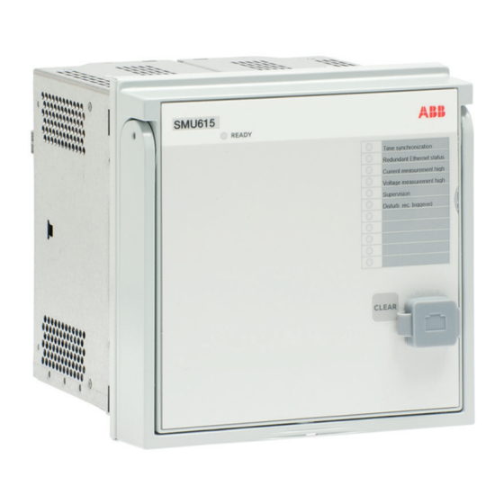
Section 7 1MRS758405 C Technical data Section 7 Technical data Case and HMI display variants 7.1.1 Front side of the merging unit GUID-F61FAD50-1151-432A-B998-2461024CAD32 V2 EN Figure 33: Front view of the merging unit SMU615 Installation Manual... -
Page 58: Rear Side Of The Merging Unit
Section 7 1MRS758405 C Technical data 7.1.2 Rear side of the merging unit GUID-4D62439F-99C6-4E5B-866C-9BEEB20FBA93 V1 EN Figure 34: Rear view of a merging unit with communication module, BIO and SMU615 Installation Manual... - Page 59 Section 7 1MRS758405 C Technical data GUID-B7A8A91C-CC78-462E-A449-EB8C51C587B7 V1 EN Figure 35: Rear view of a merging unit with communication module, BIO and SMU615 Installation Manual...
-
Page 60: Dimensions
Section 7 1MRS758405 C Technical data Dimensions GUID-D8D861C5-1CDD-4877-AAFE-D80C3448301A V1 EN Figure 36: Main dimensions 177 mm 177 mm (4U) C 164 mm D 201 mm 153 mm 48 mm G 160 mm SMU615 Installation Manual... -
Page 61: Enclosure Class
201 mm (153 + 48 mm) Weight Complete merging unit 4.1 kg Plug-in unit only 2.1 kg Enclosure class Table 4: Degree of protection of flush-mounted merging unit Description Value Front side IP 54 Rear side, connection terminals IP 20 SMU615 Installation Manual... -
Page 63: Section 8 Accessories And Ordering Data
19” rack mounting kit for one merging unit and one RTXP18 test switch (the test 2RCA021952A0003 switch is not included in the delivery) 19” rack mounting kit for one merging unit and one RTXP24 test switch (the test 2RCA022561A0003 switch is not included in the delivery) SMU615 Installation Manual... -
Page 65: Section 9 Glossary
Binary input and output Current transformer Electromagnetic compatibility International Electrotechnical Commission Liquid crystal polymer Light-emitting diode LHMI Local human-machine interface Polyamide Polybutylene terephthalate 1. Personal computer 2. Polycarbonate Power supply module RoHS Restriction of hazardous substances Voltage transformer SMU615 Installation Manual... - Page 68 — ABB Distribution Solutions Distribution Automation P.O. Box 699 FI-65101 VAASA, Finland Phone +358 10 22 11 www.abb.com/mediumvoltage www.abb.com/substationautomation © Copyright 2019 ABB. All rights reserved.
Need help?
Do you have a question about the SMU615 and is the answer not in the manual?
Questions and answers