
Related Manuals for Toro E-Z Vac 79346


Summary of Contents for Toro E-Z Vac 79346
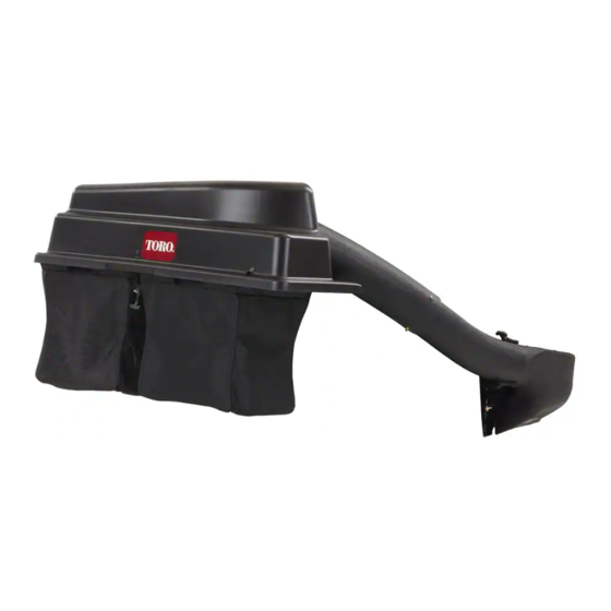
- Page 1 Form No. 3436-949 Rev A E-Z Vac ™ Complete Twin Bagger TITAN ® Zero-Turn-Radius Riding Mower Model No. 79346—Serial No. 400000000 and Up *3436-949* A Register at www.Toro.com. Original Instructions (EN)
-
Page 2: Table Of Contents
Whenever you need service, genuine Toro parts, or 2 Installing the Weight......... 6 additional information, contact an Authorized Service 3 Removing the Grass Deflector and Belt Dealer or Toro Customer Service and have the model Cover .............. 7 and serial numbers of your product ready. Figure 1... -
Page 3: Safety
Towing Safety Safety • Do not attach towed equipment except at the hitch • Become familiar with the safe operation of the point. equipment, with the operator controls, and safety • Follow the attachment manufacturer's signs. recommendation for weight limits for towed •... -
Page 4: Safety And Instructional Decals
Safety and Instructional Decals Safety decals and instructions are easily visible to the operator and are located near any area of potential danger. Replace any decal that is damaged or missing. decal136-4164 136-4164 1. Warning—read the Operator’s Manual. 4. Cutting/dismemberment hazard, impeller—keep away from moving parts;... -
Page 5: Setup
Setup Loose Parts Use the chart below to verify that all parts have been shipped. Procedure Description Qty. – No parts required Prepare the machine. Weight tray Left weight-tray mount Right weight-tray mount Suitcase weight—16 kg (35 lb) Retaining rod Install the weight. -
Page 6: Preparing The Machine
Determine the left and right sides of the machine from the normal operating position. Preparing the Machine Installing the Weight No Parts Required Parts needed for this procedure: Weight tray Procedure Left weight-tray mount Perform the following procedure to prepare the Right weight-tray mount machine for attaching the blower and finishing kit. -
Page 7: Removing The Grass Deflector And Belt Cover
g196533 Figure 3 g196560 Figure 5 Cutaway view 1. Retaining rod 3. Suitcase weight 1. Weight-tray mounts 3. Flange nut (3/8 inch) 2. Weight tray 2. Bolt (3/8 x 1-1/4 inches) 4. Self-tapping bolt (5/16 x 3/4 inch) Insert the retaining rod into the tray and rotate it into the locked position (Figure Use the 2 carriage bolts (3/8 x 1 inch) and flange... -
Page 8: Installing The Baffle And Blower Support
Note: Your chute may look different than the one pictured. Installing the Baffle and Blower Support Parts needed for this procedure: Blower support Hex washer-head screw (3/8 x 3/4 inch) Baffle Carriage bolt (5/16 x 3/4 inch) Flange nut (5/16 inch) Procedure Install the blower support to the mower deck using 2 hex washer-head screws (3/8 x 3/4 inch) - Page 9 Remove the existing bolt and nut from the mower deck (Figure Important: For 48-inch and 60-inch mower decks, there is only one bolt and nut that you can remove. For 54-inch mower deck, remove the bolt and nut as shown in Figure g206496 Figure 10...
-
Page 10: Installing The Pulley Assembly, Belt Cover, And Shoulder Bolt
Install the new belt cover over the pulley assembly using the 4 previously removed screws (1/4 x 1/2 inch) as shown in Figure Installing the Pulley Assembly, Belt Cover, and Shoulder Bolt Parts needed for this procedure: Pulley assembly Belt cover Procedure g201435 Figure 12... - Page 11 g308798 Figure 13 1. Nut 3. Bolt 2. Existing hitch bracket g302477 Figure 15 Install the stabilizer bracket to the engine guard 1. Locknut (5/16 inch) 2. Bolt (5/16 x 1 inch) using 2 carriage bolts (5/16 x 3/4 inch) and 2 locknuts (5/16 inch) as shown in Figure Position the pivot frame upward, and secure the...
-
Page 12: Installing The Latch Rod
Installing the Latch Rod Parts needed for this procedure: Latch rod Hairpin cotter Procedure Install the latch rod with a hairpin cotter (Figure 18). g308335 Figure 17 Left side shown Insert the bent ends of the rods into the attachment mount as shown in Figure 17 secure the end of each rod with a washer and hairpin cotter. -
Page 13: Assembling The Bagger Top
Assembling the Bagger Top Parts needed for this procedure: Bagger top Bagger screen Hairpin cotter Procedure Turn the bagger top over. Install the screen as shown in Figure 19 ensure that it slopes down toward the collection bags. Note: Make sure that the screens snap into place and the tabs engage the bagger top. -
Page 14: Installing The Bagger Top
Lift the bagger top and install the bags by sliding the bag frame hooks onto the retaining brackets (Figure 21). Installing the Bagger Top Parts needed for this procedure: Grass Bag Procedure Install the bagger top to the bagger frame. Note: Your bagger may look different than the one shown. -
Page 15: Installing The Blower Assembly
Installing the Blower Assembly Parts needed for this procedure: Blower assembly Procedure g201514 Figure 23 WARNING 1. Blower assembly 3. Blower support An uncovered discharge opening allows the 2. Blower pivot pin lawn mower to throw objects toward you or bystanders, resulting in serious injury. -
Page 16: Installing The Blower Belt And Powered Bagger Cover
54-inch Mower 60-inch Mower illustrative purposes) Deck Deck Deck 3. Spring 7. Idler/tension pulley Toro Part No. Toro Part No. Toro Part No. 4. Idler-pulley post 8. Blower belt 127-0074 127-0075 127-0076 Ensure that the belt remains aligned to the blower pulley while you are installing the blower assembly. -
Page 17: Installing The Discharge Tubes
g201515 Figure 27 1. Knob 3. Belt cover 2. Powered bagger cover Installing the Discharge Tubes g018444 Figure 28 Parts needed for this procedure: Lower Discharge Tube Latch Upper tube 1. Blower assembly 3. Latch Screw (1/4 x 3/4 inches) 2. - Page 18 g018440 Figure 29 1. Upper tube 3. Bagger hood 2. Rubber seal protruding out Align the upper tube holes to match the dimples on the surface of the lower tube. Note: Ensure that the side profile appears as shown in Figure Note: Do not use the open hole near the...
-
Page 19: Operation
Operation Secure the tubes together with the nuts (1/4 inch) as shown in Figure Insert the upper discharge tube through the tube WARNING seal in the hood. To avoid personal injury, follow these Pull the upper tube out slightly so that the seal extends outward and over the blower assembly procedures: (Figure... -
Page 20: Emptying The Grass Bags
Emptying the Grass Bags DANGER Debris, such as leaves, grass, or brush can catch fire. A fire in the engine area can cause personal injury and property damage. • Keep the engine and muffler area free of debris accumulation. • Take care when opening the bagger cover to keep debris from falling onto the engine and muffler area. -
Page 21: Clearing Obstructions From The Bagger
Clearing Obstructions from You can remove the bagger by repeating the Setup sections from all installed bagger related kits in the Bagger reverse order. If weights are installed, always remove the front bagger weights when removing the bagger attachments. WARNING Note: It is necessary only to remove the cutoff baffle When the bagger is in operation, the blower... -
Page 22: Operating Tips
Operating Tips CAUTION As the bagger fills, extra weight is added to Tips for Bagging the back of the machine. If you stop and start suddenly on hills, you may lose steering control or the machine may tip. Remembering the Size of the •... -
Page 23: Maintenance
Maintenance Note: Determine the left and right sides of the machine from the normal operating position. Recommended Maintenance Schedule(s) Maintenance Service Maintenance Procedure Interval • Inspect the blower belt. After the first 8 hours • Inspect the bagger. • Clean the hood screen. After each use •... -
Page 24: Cleaning The Bagger And Bags
Cleaning the Bagger and Remove the existing bagger belt from the mower-deck pulley. Bags Remove the blower from the mower deck. Service Interval: After each use Remove the existing bagger belt from the blower pulleys. Wash the inside and outside of the bagger hood, bags, tube, and the underside of the mower. -
Page 25: Storage
Storage Storing the Bagger Attachment Clean the bagger attachment; refer to Cleaning the Bagger Attachment. Inspect the bagger attachment for damage; refer to Inspecting the Bagger Attachment. Ensure that the grass bags are empty and thoroughly dry. Store the bagger in a clean, dry place, out of direct sunlight. -
Page 26: Troubleshooting
Troubleshooting Problem Possible Cause Corrective Action There is abnormal vibration. 1. The cutting blade(s) are bent or 1. Install new cutting blade(s). unbalanced. 2. The blade-mounting bolt is loose. 2. Tighten the blade-mounting bolt. 3. There is a loose blower pulley or pulley 3. - Page 27 The Toro Company (“Toro”) respects your privacy. When you purchase our products, we may collect certain personal information about you, either directly from you or through your local Toro company or dealer. Toro uses this information to fulfil contractual obligations - such as to register your warranty, process your warranty claim or to contact you in the event of a product recall - and for legitimate business purposes - such as to gauge customer satisfaction, improve our products or provide you with product information which may be of interest.
- Page 28 While the exposure from Toro products may be negligible or well within the “no significant risk” range, out of an abundance of caution, Toro has elected to provide the Prop 65 warnings. Moreover, if Toro does not provide these warnings, it could be sued by the State of California or by private parties seeking to enforce Prop 65 and subject to substantial penalties.
Need help?
Do you have a question about the E-Z Vac 79346 and is the answer not in the manual?
Questions and answers