Table of Contents
Advertisement
Quick Links
SPLIT-TYPE AIR CONDITIONERS
INDOOR UNIT
SERVICE MANUAL
Models
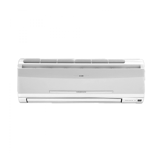
MS-GF20VA
MS-GF25VA
MS-GF35VA
MS-GF50VA
MS-GF60VA
MS-GF80VA
NOTE:
RoHS compliant products have <G> mark on the spec name plate.
-
E1
-
E1
-
E1
-
E1
-
E1
-
E1
CONTENTS
1. TECHNICAL CHANGES ···································
2. PART NAMES AND FUNCTIONS ····················· 3
3. SPECIFICATION ················································
4. NOISE CRITERIA CURVES ······························
5. OUTLINES AND DIMENSIONS ························
6. WIRING DIAGRAM ············································
7. REFRIGERANT SYSTEM DIAGRAM ············· 10
8. SERVICE FUNCTIONS ···································
9. MICROPROCESSOR CONTROL ··················· 14
10. TROUBLESHOOTING ·····································
11. DISASSEMBLY INSTRUCTIONS ···················· 35
PARTS CATALOG (OBB621)
Revision A:
• MS-GF50VA-
, MS-GF60VA-
E1
MS-GF80VA-
have been added.
E1
Please void OBH621.
No. OBH621
REVISED EDITION-A
Outdoor unit service manual
MU-GF·VA Series (OBH622)
and
E1
2
5
6
8
9
12
21
Advertisement
Table of Contents

Related Manuals for Mitsubishi Electric MS-GF50VA-E1


Summary of Contents for Mitsubishi Electric MS-GF50VA-E1
-
Page 1: Table Of Contents
Revision A: • MS-GF50VA- , MS-GF60VA- MS-GF80VA- have been added. SPLIT-TYPE AIR CONDITIONERS Please void OBH621. INDOOR UNIT No. OBH621 SERVICE MANUAL REVISED EDITION-A Models MS-GF20VA MS-GF25VA MS-GF35VA MS-GF50VA MS-GF60VA MS-GF80VA Outdoor unit service manual MU-GF·VA Series (OBH622) CONTENTS 1. TECHNICAL CHANGES ··································· 2. -
Page 2: Technical Changes
Use the specif ed refrigerant only Never use any refrigerant other than that specified. Doing so may cause a burst, an explosion, or fire when the unit is being used, serviced, or disposed of. Correct refrigerant is specified in the manuals and on the spec labels provided with our products. We will not be held responsible for mechanical failure, system malfunction, unit breakdown or accidents caused by failure to follow the instructions. -
Page 3: Part Names And Functions
PART NAMES AND FUNCTIONS MS-GF20VA MS-GF25VA MS-GF35VA Front panel Air f lter (Nano platinum f lter) Air cleaning f lter (Electrostatic anti-allergy enzyme f lter, option) Air inlet Remote controller Air outlet Heat exchanger Horizontal vane Display section Remote control receiving section Operation indicator lamp Emergency operation switch (E.O. - Page 4 MS-GF50VA MS-GF60VA MS-GF80VA Front panel Air f lter (Nano platinum f lter) Air cleaning f lter (Electrostatic anti-allergy enzyme f lter, option) Air inlet Remote controller Air outlet Heat exchanger Horizontal vane Display section Operation indicator lamp Emergency operation switch (E.O.SW) Remote control receiving section ACCESSORIES...
-
Page 5: Specification
SPECIFICATION Indoor model MS-GF20VA MS-GF25VA MS-GF35VA MS-GF50VA MS-GF60VA MS-GF80VA Function Cooling Power supply Single phase 230 V, 50 Hz Running current 0.20 0.22 0.30 0.42 Power input Model RC4V18-FA RC0J56-AF Current 0.22 0.30 0.42 0.20 Dimensions W × H × D 798 x 295 x 232 1,100 x 325 x 238 Weight... -
Page 6: Noise Criteria Curves
NOISE CRITERIA CURVES MS-GF20VA MS-GF25VA FAN SPEED FUNCTION SPL(dB(A)) LINE FAN SPEED FUNCTION SPL(dB(A)) LINE Super High COOLING Super High COOLING NC-70 NC-70 NC-60 NC-60 NC-50 NC-50 NC-40 NC-40 NC-30 NC-30 NC-20 NC-20 NC-10 NC-10 1000 2000 4000 8000 1000 2000 4000 8000... - Page 7 MS-GF50VA MS-GF60VA FAN SPEED FUNCTION SPL(dB(A)) LINE FAN SPEED FUNCTION SPL(dB(A)) LINE Super High COOLING Super High COOLING NC-70 NC-70 NC-60 NC-60 NC-50 NC-50 NC-40 NC-40 NC-30 NC-30 NC-20 NC-20 NC-10 NC-10 1000 2000 4000 8000 1000 2000 4000 8000 BAND CENTER FREQUENCIES, Hz BAND CENTER FREQUENCIES, Hz MS-GF80VA...
-
Page 8: Outlines And Dimensions
OUTLINES AND DIMENSIONS Unit: mm MS-GF20VA MS-GF25VA MS-GF35VA 11×20 Oblong hole 11×26 Oblong hole Installation plate Wall hole ø65 Air in Indoor unit Installation plate Piping Drain hose Air out Insulation ø35 O.D Liquid line ø7 - 0.5 m (Flared connection ø6.35) Gas line ø9.52 - 0.43 m (Flared connection: ø9.52) Drain hose... -
Page 9: Wiring Diagram
WIRING DIAGRAM MS-GF20VA MS-GF25VA MS-GF35VA MS-GF50VA MS-GF60VA MS-GF80VA OBH621A... -
Page 10: Refrigerant System Diagram
REFRIGERANT SYSTEM DIAGRAM MS-GF20VA MS-GF25VA Unit: mm Refrigerant pipe 9.52 (with heat insulator) Indoor coil Indoor thermistor heat RT12 exchanger Flared connection Room temperature thermistor RT11 Flared connection Refrigerant pipe 6.35 (with heat insulator) Refrigerant flow in cooling MS-GF35VA Refrigerant pipe 9.52 (with heat insulator) Indoor coil... - Page 11 MS-GF50VA MS-GF60VA MS-GF80VA Unit: mm Refrigerant pipe ø12.7 (MS-GF50VA) ø15.88 (MS-GF60/80VA) (with heat insulator) Indoor coil Indoor thermistor heat RT12 exchanger Flared connection Room temperature thermistor RT11 Flared connection Refrigerant pipe ø6.35 (MS-GF50/60VA) ø9.52 (MS-GF80VA) (with heat insulator) Refrigerant flow in cooling OBH621A...
-
Page 12: Service Functions
SERVICE FUNCTIONS MS-GF20VA MS-GF25VA MS-GF35VA MS-GF50VA MS-GF60VA MS-GF80VA 8-1. TIMER SHORT MODE For service, the following set time can be shortened by short circuit of JPG and JPS on the electronic control P.C. board. (Refer to 10-7.) Set time: 3 minutes → 3 seconds (It takes 3 minutes for the compressor to start operation. However, the starting time is shortened by short circuit of JPG and JPS.) 8-2. - Page 13 8-3. AUTO RESTART FUNCTION When the indoor unit is controlled with the remote controller, the operation mode, the set temperature, and the fan speed are memorized by the indoor electronic control P.C. board. “AUTO RESTART FUNCTION” automatically starts operation in the same mode just before the shutoff of the main power. Operation If the main power has been cut, the operation settings remain.
-
Page 14: Microprocessor Control
MICROPROCESSOR CONTROL WIRELESS REMOTE CONTROLLER MS-GF20VA MS-GF25VA MS-GF35VA Signal transmitting section Operation display section FAN SPEED CONTROL button OPERATE/STOP OFF-TIMER button (ON/OFF) button OPERATION SELECT button ON-TIMER button ECONO COOL button TIME SET buttons POWERFUL COOL button FORWARD button Temperature buttons BACKWARD button CLOCK button RESET button... - Page 15 INDOOR UNIT DISPLAY SECTION MS-GF20VA MS-GF25VA MS-GF35VA Operation Indicator lamp The operation indicator at the right side of the indoor unit indicates the operation state. •The following indication applies regardless of shape of the indication. Indication Operation state Room temperature Lighted The unit is operating to About 2°C or more away...
- Page 16 9-2. DRY ( ) OPERATION (1) Press OPERATE/STOP (ON/OFF) button. OPERATION INDICATOR lamp of the indoor unit turns on with a beep tone. (2) Select DRY mode with OPERATION SELECT button. (3) The set temperature is determined from the initial room temperature. 1.
- Page 17 (4) The initial set temperature is decided by the initial room temperature. Initial room temperature Initial set temperature Mode 26 °C or more 24 °C COOL mode of “I FEEL CONTROL” Initial room temperature 25 °C to 26 °C °C minus 2 Initial room temperature DRY mode of...
- Page 18 (5) STOP (operation OFF) and ON TIMER standby In the following cases, the horizontal vane returns to the closed position. (a) When OPERATE/STOP (ON/OFF) button is pressed (POWER OFF). (b) When the operation is stopped by the emergency operation. (c) When ON TIMER is ON standby. (6) Dew prevention During COOL or DRY operation with the vane angle at Angle 4 or 5 when the compressor cumulative operation time exceeds 1 hour, the vane angle automatically changes to Angle 1 for dew prevention.
- Page 19 9-6. TIMER OPERATION 1. How to set the time (1) Check that the current time is set correctly. NOTE: Timer operation will not work without setting the current time. Initially “0:00” blinks at the current time display of TIME MONITOR, so set the current time correctly with CLOCK button. How to set the current time (a) Press the CLOCK button.
- Page 20 9-7. EMERGENCY/TEST OPERATION Operation mode COOL In case of test run operation or emergency operation, use EMERGENCY OPERATION switch on the right side of the indoor unit. Set temperature 24°C Emergency operation is available when the remote controller is miss- Fan speed Med.
-
Page 21: Troubleshooting
TROUBLESHOOTING MS-GF20VA MS-GF25VA MS-GF35VA MS-GF50VA MS-GF60VA MS-GF80VA 10-1. CAUTIONS ON TROUBLESHOOTING 1. Before troubleshooting, check the following 1) Check the power supply voltage. 2) Check the indoor/outdoor connecting wire for miswiring. 2. Take care of the following during servicing 1) Before servicing the air conditioner, be sure to turn OFF the main unit first with the remote controller, and then after confirming the horizontal vane is closed, turn OFF the breaker and/or disconnect the power plug. - Page 22 10-2. FAILURE MODE RECALL FUNCTION Outline of the function This air conditioner can memorize the abnormal condition which has occurred once. Even though LED indication listed on the troubleshooting check table (10-4.) disappears, the memorized failure details can be recalled. 1.
- Page 23 2. Indoor unit failure mode table Upper lamp of OP- Abnormal point ERATION INDICA- Condition Remedy (Failure mode) TOR lamp Not lighted Normal — — The room temperature thermistor short or 1-time f ash every Room temperature Refer to the characteristics of the room temperature open circuit is detected every 8 seconds dur- 0.5-second thermistor...
- Page 24 10-3. INSTRUCTION OF TROUBLESHOOTING Start Indoor unit does Indoor unit oper- OPERATION INDICATOR Indoor and not receive the ates. lamp on the indoor unit is outdoor unit Outdoor unit signal from re- f ashing ON and OFF. do not operate. mote controller.
- Page 25 10-4. TROUBLESHOOTING CHECK TABLE Before taking measures, make sure that the symptom reappears for accurate troubleshooting. When the indoor unit has started operation and detected an abnormality of the following condition (the first detection after the power ON), the indoor fan motor turns OFF and OPERATION INDICATOR lamp flashes. Operation Indicator lamp The operation indicator lamp is at the right side of the indoor unit.
- Page 26 10-5. TROUBLE CRITERION OF MAIN PARTS Part name Check method and criterion Figure Measure the resistance with a tester. Room temperature thermistor (RT11) Refer to 10-7. "Test point diagram and voltage", "1. Indoor electronic control Indoor coil thermistor P.C. board", for the chart of thermistor. (RT12) Measure the resistance with a tester.
- Page 27 10-6. TROUBLESHOOTING FLOW A Check of indoor fan motor MS-GF20/25/35VA Turn OFF the power supply. Check connector CN211 visually. Are soldered points of the Reconnect the lead wires. Are lead wires connected? Resolder it. connector correctly soldered to the indoor power P.C. board? Disconnect lead wires from connector CN211 on indoor power P.C.
- Page 28 MS-GF50/60/80VA The indoor fan motor error has occurred, and the indoor fan does not operate. Turn OFF the power supply. Pay enough attention to the high voltage on the fan motor connector CN211. Turn ON the power supply, wait 5 seconds or more, and then press EMERGENCY OPERATION switch.
- Page 29 B Check of remote controller and indoor electronic control P.C. board Check if the remote controller is exclusive for this air conditioner. MS-GF20/25/35VA Press OPERATE/STOP (ON/OFF) button on the remote controller. Is LCD display on the remote controller Replace the batteries. (Refer to 10-1.4.) visible? (Not clear) Remove the batteries, then set them back...
- Page 30 Check of indoor electronic control P.C. board and indoor fan motor MS-GF20/25/35VA Turn OFF the power supply. Remove indoor fan motor connector CN211 from indoor Measure the resistance of indoor fan motor. Short circuit Refer to 10-5. Replace the indoor fan motor. power P.C.
- Page 31 MS-GF50/60/80VA Turn OFF the power supply. Remove indoor fan motor connector CN211 and Short circuit: Measure the resistance between CN211 Replace the indoor fan motor. vane motor connector CN151 from the indoor electronic of the indoor fan motor connector. control P.C. board and turn ON the power supply. Does the unit operate with the remote controller? Measure the resistance of the horizontal vane Short circuit:...
- Page 32 D Electromagnetic noise enters into TV sets or radios Is the unit earthed? Earth the unit. Is the distance between the antennas Extend the distance between the antennas and and the indoor unit within 3 m, or is the the indoor unit, and/or the antennas and the distance between the antennas and the outdoor unit.
- Page 33 10-7. TEST POINT DIAGRAM AND VOLTAGE 1. Indoor electronic control P.C. board MS-GF20VA MS-GF25VA MS-GF35VA Timer short mode point JPG, JPS (Refer to 8-1.) Room temperature thermistor RT11 (CN111) Indoor coil thermistor RT12 (CN112) Vane motor (CN151) Indoor coil thermistor (RT12) Room temperature thermistor (RT11) Connector to Indoor power P.C.
- Page 34 3. Indoor electronic control P.C. board, Indoor terminal P.C. board, Power monitor receiver SW P.C. board MS-GF50VA MS-GF60VA MS-GF80VA Indoor electronic control P.C. board To disable "Auto restart function", Indoor terminal P.C. board Indoor coil thermistor cut the Jumper wire to JR77. RT12 (main) (CN112) (Refer to 8-3.) Fuse...
-
Page 35: Disassembly Instructions
DISASSEMBLY INSTRUCTIONS <"Terminal with locking mechanism" Detaching points> The terminal which has the locking mechanism can be detached as shown below. There are two types (refer to (1) and (2)) of the terminal with locking mechanism. The terminal without locking mechanism can be detached by pulling it out. Check the shape of the terminal before detaching. - Page 36 OPERATING PROCEDURE PHOTOS Electrical box 2. Removing the indoor electronic control P.C. Photo 2 Earth wire board and the room temperature thermistor Screw of the (1) Remove the panel (Refer to 1.) and the corner box. electrical cover (2) Remove the screw of the V.A. clamp and the V.A. clamp.
- Page 37 OPERATING PROCEDURE PHOTOS 4. Removing the nozzle assembly Photo 4 (1) Remove the panel (Refer to 1.) and the corner box. Screws of horizontal vane motor unit (2) Remove the indoor/outdoor connecting wire (Refer to 2 (2)-(4).). (3) Remove the indoor electronic control P.C. board holder. (4) Pull out the drain hose from the nozzle assembly and remove the nozzle assembly.
- Page 38 OPERATING PROCEDURE PHOTOS 6. Removing the indoor fan motor, the indoor coil Photo 5 thermistor, and the line flow fan (1) Remove the panel (Refer to 1.) and the corner box. (2) Remove the indoor electronic control P.C. board hold- er, the electrical box and the nozzle assembly.
- Page 39 11-2. MS-GF50VA MS-GF60VA MS-GF80VA NOTE: Turn OFF power supply before disassembly. OPERATING PROCEDURE PHOTOS 1. Removing the panel Photo 1 (1) Remove the horizontal vanes. Horizontal vanes Front panel (2) Remove the screw caps of the panel. Remove the screws of the panel. (3) Hold the lower part of both ends of the panel and pull it slightly toward you, and then remove the panel by pushing it upward.
- Page 40 OPERATING PROCEDURE PHOTOS 4. Removing the nozzle assembly Photo 4 (1) Remove the panel (Refer to 1.) and the corner box. (2) Remove the V.A. clamp, and then the indoor/outdoor connecting wire. (Photo 2) (3) Remove the electrical cover. (Photo 2) (4) Disconnect the following connectors on the electronic control P.C.
- Page 41 OPERATING PROCEDURE PHOTOS 7. Removing the water cut, the indoor fan motor, Photo 8 the indoor coil thermistor, and the line flow fan (1) Remove the panel (Refer to 1.) and the corner box. (2) Remove the power monitor receiver holder, the electri- cal box and the nozzle assembly.
- Page 42 HEAD OFFICE: TOKYO BLDG., 2-7-3, MARUNOUCHI, CHIYODA-KU, TOKYO 100-8310, JAPAN © Copyright 2012 MITSUBISHI ELECTRIC CORPORATION Distributed in Feb. 2013. No. OBH621 REVISED EDITION-A Distributed in Oct. 2012. No. OBH621 New publication, effective Feb. 2013 Made in Japan Specifications are subject to change without notice.
Need help?
Do you have a question about the MS-GF50VA-E1 and is the answer not in the manual?
Questions and answers