ABB 2600T Series Instructions For Installation Manual
Hide thumbs
Also See for 2600T Series:
- Instruction manual (136 pages) ,
- Operating instructions manual (96 pages) ,
- Operating instruction (84 pages)

Related Manuals for ABB 2600T Series


Summary of Contents for ABB 2600T Series
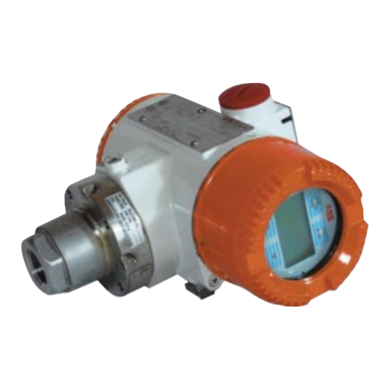
- Page 1 2600T Series Safety Pressure Instruction for installation Transmitters and commissioning PED/268H_2 Models 268H/N - 1 -...
- Page 2 Cert. No. Q5907 As a part of ABB, a world leader in process automation technology , we offer customers application expertise, service and support worldwide. ISO 9001: 2000 We are committed to teamwork, high quality manufacturing, advanced technology and unrivalled service and support.
-
Page 3: Table Of Contents
This document provides basic instruction for the installation Section Page and commissioning of the ABB 2600T. This transmitter is connected to a process by means of impulse lines and can 1. INTRODUCTION ............3 measure Pressure or Absolute pressure. The measurement is transmitted to a control system by means of a 4-20 mA signal 2. -
Page 4: Phase 1 - Preliminary Checks
PHASE 1 - PRELIMINARY CHECKS that all the parameters listed on this label (or on the certificates 2. PRELIMINARY CHECKS enclosed with the transmitter) are in accordance with the Before mounting the transmitter, check the compatibility with requirements of the area where the transmitter is going to be the following measurement and safety requirements: installed. -
Page 5: Pressure And Temperature Limits
(the manual is available at www.abb.com inserting - 21MPa, 210bar, 3045psi for sensor codes P, Q, S in the “search” tool the keyword “IM/26X”) or from local ABB representatives. For EEx ia and intrinsically safe (FM, CSA and SAA) approvals,... -
Page 6: Environmetal Limits
Electromagnetic compatibility (EMC) process flanges and sensor diaphragm. Complies with EN 50081–1 for emission and EN 50082–2 for A fluid / material compatibility table is available at www.abb.com immunity requirements and test; (inserting in the “search” tool the keyword “TB/COR”) or from Radiated electromagnetic immunity level: 30V/m (according to local ABB representatives. -
Page 7: Phase 2 - Transmitter Installation
PHASE 2 - TRANSMITTER INSTALLATION 3. TRANSMITTER INSTALLATION The following examples are standard mounting locations for instrumentation suitable for these main types of applications: TRANSMITTER LOCATION Level measurement with open tanks 1. Mount the transmitter at the same height or below of the lowest level to be measured. - Page 8 PHASE 2 - TRANSMITTER INSTALLATION Pressure or absolute pressure measurement of a liquid in a pipe 1. Place the tap at the side of the line. Dirty fluids 2. Mount the transmitter beside or below the tap for clean fluids, above the tap for dirty fluids. 3.
-
Page 9: Transmitter Mounting
PHASE 2 - TRANSMITTER INSTALLATION TRANSMITTER MOUNTING Orient the process flanges to enable process connections to be made. It is important to mount the transmitter and to lay the process piping so that gas bubbles, when measuring liquids, or condensate when measuring gases, can flow back into the process. -
Page 10: Rotation
PHASE 2 - TRANSMITTER INSTALLATION ROTATION Housing Rotation To improve field access to wiring or the readability of the optional LCD meter it is possible to rotate the Housing and the Meters or the Integral display. Housing Rotation Unlock the housing rotation set screw by turning it 1 turn (use the 3 mm Allen key supplied with the instrument) Turn the housing clock wise or counterclockwise up to 180°... -
Page 11: Phase 3 - Transmitter Wiring
PHASE 3 - TRANSMITTER WIRING 5. Run the cable through the cable gland and the open port. TRANSMITTER WIRING 6. Connect the positive lead to the + terminal, and the negative lead to the – terminal. PROTECTIVE GROUNDING All transmitters are supplied with an external ground connection ✶... -
Page 12: Phase 4 - Transmitter Operation
PHASE 4 - TRANSMITTER OPERATION 5. TRANSMITTER OPERATION Use the following step to adjust the transmitter zero. PRESSURE MEASUREMENT 1. Slowly open the gate valve to admit process fluid to primary of side H. 2. Vent all entrapped air (liquid service) or drain any condensate (gas service) from primary using the vent/drain valve. 3. -
Page 13: Level Measurement
PHASE 4 - TRANSMITTER OPERATION LEVEL MEASUREMENT 1. Vent all entrapped air from primary using vent/drain valves on the transmitter, then close them. Max. Level 2. Make sure to have the level in the tank at the required Max. Level reference (minimum) level Note - In case it is not possible to empty the tank, it is possible to follow the Zero Raise/Lower adjustment... -
Page 14: Dismantling And Reassembly
DISMANTLING AND REASSEMBLY Reassembly WARNING - Process fluids and/or pressure retained in the transmitter primary unit can cause severe injury and WARNING - Assembling flanges with incorrect death or damage to the equipment. It is the user fixing bolts and nuts and improper "O rings" can cause responsibility to make sure that no pressure is applied fracture or overstressing of bolts and release of pressurized before removing the instrument from service or when... - Page 15 - 15 -...
- Page 16 - 16 -...
- Page 17 - 17 -...
- Page 18 - 18 -...
- Page 19 Service and Repair Centre. – Food & Beverage – Manufacturing Italy – Metals and Minerals – Oil, Gas & Petrochemical ABB S.p.A. – Pulp and Paper Business Unit Measurement Products Tel: +39 0344 58111 Fax: +39 0344 56278 Drives and Motors •...
- Page 20 The Company’s policy is one of continuous product ABB has Sales & Customer Support improvement and the right is reserved to modify the expertise in over 100 countries worldwide information contained herein without notice. Printed in Italy (01.2009) www.abb.com/instrumentation © ABB 2012 ABB Ltd ABB S.p.A.
Need help?
Do you have a question about the 2600T Series and is the answer not in the manual?
Questions and answers