LG LGES-5048 Quick Installation Manual
Hide thumbs
Also See for LGES-5048:
- Quick installation instructions (4 pages) ,
- User manual (18 pages) ,
- User manual (37 pages)
Table of Contents
Advertisement
Quick Links
Advertisement
Table of Contents

Related Manuals for LG LGES-5048


Summary of Contents for LG LGES-5048
- Page 1 Quick Installation Guide Hybrid Inverter LGES-5048 V1.0 -2021 -11-01...
-
Page 2: Safety Precautions
Strictly follow the installation, operation, and configuration instructions in this guide and user manual. The manufacturer shall not be liable for equipment damage or personal injury if you do not follow the instructions. For more warranty details, please visit https //www.lgessbattery.com/au/ home-battery/product-info.lg Safety Disclaimer WARNING DC Side 1. - Page 3 Inverter 1. Terminals at the bottom of the inverter cannot bear much load. Otherwise, the terminals will be damaged. 2. All labels and warning marks should be clear after the installation. Do not scrawl, damage, or cover any label on the device. 3.
-
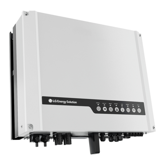
Page 4: Product Introduction
Product Introduction Parts Communication Module Battery Terminal (BATTERY PV Input Terminal +/-) (PV1/PV2) Port (WiFi/LAN) DRED or Remote METER Communication Shutdown BMS Communication Port Port Communication Port RS485 Communication AC Terminal (ON-GRID/ Reserved Port Port BACKUP) 10. Indicators Mounting Plate 12. -
Page 5: Inverter Installation
Inverter Installation Packing List x 10 [a] The communication module can be used as a WiFi module or LAN module. Space Requirement ≥300mm ≥200mm ≥200mm ≥300mm ≥500mm... - Page 6 IP65 0%~95%RH Angle Requirements Inverter Installation Avoid water pipes and cables buried in the wall when drilling holes. The lock and its accessories should be prepared by customers. Φ: 10mm Depth: 80mm...
-
Page 7: Electrical Connection
Electrical Connection Connecting the PE Cable L=L1+(1~2)mm Copper, 4~6mm 1.2~2N·m Connecting the AC Cable (ON-GRID & BACKUP) 0.6~0.8N·m 7-9mm 20-25mm Φ: 13-18mm Copper, 4mm ≤S≤6mm... - Page 8 Connecting the DC Cable (PV) Click 7~8mm Φ: 4~5mm 7~8mm 2.5mm ≤S≤4mm Use a multimeter to measure the DC voltage and check the polarity of the connectors. Click Click...
-
Page 9: Communication Connection
Connecting the Battery Cable (BATTERY) 0.6~0.8N·m 10mm Φ: 10~14mm 10mm Φ: 10~14mm 20mm ≤S≤35mm 7~9N·m Communication Connection Connecting the DRED Communication Cable 6~8mm 25mm... - Page 10 1: DRM 1/5 2: DRM2/6 3: DRM3/7 4: DRM4/8 5: REFGEN 6: COM/DRMO 0.8N·m Connecting the Remote Shutdown Communication Cable 6~8mm 25mm 5: REFGEN 6: COM/DRMO 0.8N·m...
- Page 11 Connecting BMS or Smart Meter To Battery Reserved To Smart Meter RS485 (to third party Color Smart Meter EMS devices) Orange&White 485_A2 485_A Orange 485_B Green&White 485_B2 485_B1 485_A Blue CAN_H Blue&White CAN_L Green 485_A1 485_B Brown&White 485_B1 Brown 485_A1 Connecting the Communication Module Notice Use the delivered module remover when removing the communication module.
-
Page 12: Wiring System
Wiring System DC Breaker AC Breaker AC Breaker AC Breaker... - Page 13 Wiring with SP3T Bypass Switch Notice The purpose of SP3T bypass switch is to allow for continued operation of back-up loads in case of inverter fault. SP3T bypass switch is not provided with inverter, it can be purchased from electrical wholesalers. Distribution box Bypass Switch Back-Up...
-
Page 14: Led Indicators
LED Indicators Commissioning and Monitoring Commissioning via LGES PV Master App play LGES PV Master App Store <10m <5m LGES PV Master... - Page 15 Bluetooth:SOL-BLE******** WiFi: Solar-WiFi******** * are the last 8 digits of the inverter SN. WiFi initial password: 12345678 Initial Password lgresuinstaller Configure basic settings following the hints after log...
- Page 16 Monitoring via LG RESU HOME App play LG RESU HOME App Store LG RESU HOME App Configure WiFi following Contact Dealer for password. the WiFi Configuration If you are Dealer, use existing Instruction. For WiFi module organisation code and only.
- Page 17 LG Energy Solution Australia Pty Ltd Unit 12, 35 Dunlop Rd, Mulgrave, VIC 3170 www.lghomebattery.com/au essserviceau@lgensol.com 340-00567-01...
Need help?
Do you have a question about the LGES-5048 and is the answer not in the manual?
Questions and answers