Table of Contents
Advertisement
Quick Links
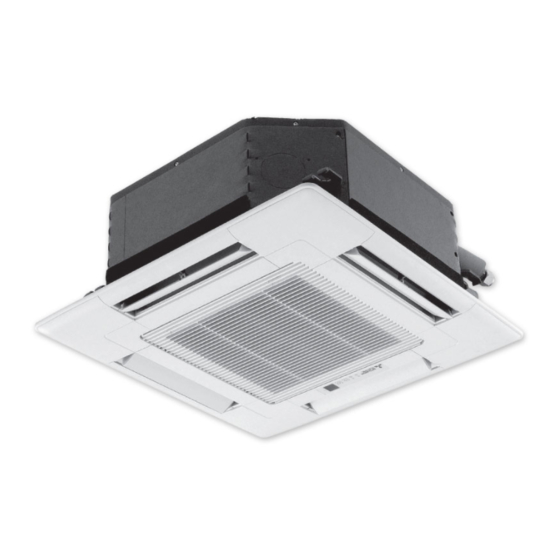
SPLIT-TYPE, HEAT PUMP AIR CONDITIONERS
TECHNICAL & SERVICE MANUAL
Indoor unit
[Model Name]
[Service Ref.]
SLZ-KA25VAQ
SLZ-KA25VAQ2
SLZ-KA35VAQ
SLZ-KA50VAQ
Model name
indication
INDOOR UNIT
TEMP.
ON/OFF
WIRED REMOTE CONTROLLER
SLZ-KA25VAQ.TH
SLZ-KA25VAQR1.TH
SLZ-KA25VAQ2.TH
SLZ-KA35VAQ.TH
SLZ-KA35VAQR1.TH
SLZ-KA35VAQR2.TH
SLZ-KA50VAQ.TH
SLZ-KA50VAQR1.TH
SLZ-KA50VAQR2.TH
(Option)
September 2013
REVISED EDITION-E
Revision:
• Added connectable outdoor unit
SUZ-KA25/35/50VA4.TH
in REVISED EDITION-E.
• Some descriptions have been
modified.
• Please void OCH493
REVISED EDITION-D.
Note:
• This manual describes only
service data of the indoor units.
CONTENTS
1. TECHNICAL CHANGES ...................... 2
2. REFERENCE SERVICE MANUAL ...... 2
3. PARTS NAMES AND FUNCTIONS ..... 2
4. SPECIFICATIONS ............................... 6
5. OUTLINES AND DIMENSIONS ........... 8
6. WIRING DIAGRAM ............................ 10
7. REFRIGERANT SYSTEM DIAGRAM ..... 11
8. TROUBLESHOOTING ....................... 12
9. 4-WAY AIR FLOW SYSTEM .............. 25
10. DISASSEMBLY PROCEDURE .......... 27
PARTS CATALOG (OCB493)
No. OCH493
Advertisement
Table of Contents

Related Manuals for Mitsubishi Electric SLZ-KA25VAQ


Summary of Contents for Mitsubishi Electric SLZ-KA25VAQ
-
Page 1: Table Of Contents
No. OCH493 REVISED EDITION-E TECHNICAL & SERVICE MANUAL Indoor unit Revision: • Added connectable outdoor unit [Model Name] [Service Ref.] SUZ-KA25/35/50VA4.TH SLZ-KA25VAQ.TH in REVISED EDITION-E. SLZ-KA25VAQ • Some descriptions have been modified. SLZ-KA25VAQR1.TH • Please void OCH493 SLZ-KA25VAQ2.TH SLZ-KA25VAQ2 REVISED EDITION-D. -
Page 2: Technical Changes
We will not be held responsible for mechanical failure, system malfunction, unit breakdown or accidents caused by failure to follow the instructions. TECHNICAL CHANGES SLZ-KA35VAQR1.TH SLZ-KA35VAQR2.TH SLZ-KA50VAQR1.TH SLZ-KA50VAQR2.TH • INDOOR CONTROLLER BOARD has been changed. SLZ-KA25VAQ.TH SLZ-KA25VAQR1.TH SLZ-KA35VAQ.TH SLZ-KA35VAQR1.TH SLZ-KA50VAQ.TH SLZ-KA50VAQR1.TH • TURBO FAN and WASHER have been changed. REFERENCE SERVICE MANUAL 2-1. - Page 3 3-2. Wired remote controller (Option) PAR-30MAA The functions which can be used are restricted according to the model. The main display can be displayed in two different modes: "Full" and "Basic." Display The initial setting is "Full." 1 Operation mode Indoor unit operation mode appears here.
- Page 4 Main menu list Setting and display items Setting details Vane · Louver · Vent. Use to set the vane angle. • Select a desired vane setting from fi ve different settings. (Lossnay) Use to turn ON / OFF the louver. •...
- Page 5 3-3. Wired remote controller (Option) PAR-21MAA Once the controllers are set, the same operation mode can be repeated by simply pressing the ON/OFF button. * The functions which can be used are restricted according to the model. “Sensor” indication Day-of-Week Display Section Shows the current day of the week.
-
Page 6: Specifications
SPECIFICATIONS SLZ-KA35VAQ.TH SLZ-KA50VAQ.TH SLZ-KA25VAQ.TH SLZ-KA25VAQ2.TH SLZ-KA50VAQR1.TH SLZ-KA35VAQR1.TH Indoor service ref. SLZ-KA25VAQR1.TH SLZ-KA35VAQR2.TH SLZ-KA50VAQR2.TH Function Cooling Cooling Cooling Heating Heating Heating Cooling Heating Single phase Single phase Single phase Single phase Power supply 230V, 50Hz 230V, 50Hz 230V, 50Hz 230V, 50Hz... - Page 7 NOISE CRITERION CURVES <50Hz> <50Hz> SLZ-KA25VAQ2.TH SLZ-KA25VAQ.TH NOTCH SPL(dB) LINE NOTCH SPL(dB) LINE SLZ-KA35VAQ.TH High High SLZ-KA25VAQR1.TH SLZ-KA35VAQR1.TH Medium Medium SLZ-KA35VAQR2.TH NC-70 NC-70 NC-60 NC-60 NC-50 NC-50 NC-40 NC-40 NC-30 NC-30 APPROXIMATE APPROXIMATE THRESHOLD OF THRESHOLD OF HEARING FOR HEARING FOR...
-
Page 8: Outlines And Dimensions
OUTLINES AND DIMENSIONS SLZ-KA25VAQ.TH SLZ-KA35VAQ.TH SLZ-KA50VAQ.TH Unit: mm SLZ-KA25VAQR1.TH SLZ-KA35VAQR1.TH SLZ-KA50VAQR1.TH SLZ-KA25VAQ2.TH SLZ-KA35VAQR2.TH SLZ-KA50VAQR2.TH Fresh air intake Detail drawing of fresh air intake Suspension bolt pitch 73.4 2.8 hole Cut out hole Burring hole Ceiling surface 15~37 576~620 Ceiling hole... - Page 9 Unit: mm WIRED REMOTE CONTROLLER (Option) 19.5 PAR-21MAA PAR-30MAA OCH493E...
-
Page 10: Wiring Diagram
WIRING DIAGRAM SLZ-KA25VAQ.TH SLZ-KA35VAQ.TH SLZ-KA50VAQ.TH SLZ-KA25VAQR1.TH SLZ-KA35VAQR1.TH SLZ-KA50VAQR1.TH SLZ-KA25VAQ2.TH SLZ-KA35VAQR2.TH SLZ-KA50VAQR2.TH GRILLE OUTDOOR UNIT CNSK SKY BLU 1 3 5 7 9 PINK (POWER (POWER DC13.1V CNDK FUSE CN3C CN2S LED2 X6 X5 X4 LED1 (POWER CN2D LED3 LED2 LED1... -
Page 11: Refrigerant System Diagram
REFRIGERANT SYSTEM DIAGRAM SLZ-KA25VAQ.TH SLZ-KA35VAQ.TH SLZ-KA50VAQ.TH SLZ-KA25VAQR1.TH SLZ-KA35VAQR1.TH SLZ-KA50VAQR1.TH SLZ-KA25VAQ2.TH SLZ-KA35VAQR2.TH SLZ-KA50VAQR2.TH Strainer Heat exchanger Refrigerant GAS pipe connection (Flare) Condenser/evaporator temperature thermistor (TH5) Refrigerant flow in cooling Refrigerant flow in heating Refrigerant LIQUID pipe connection (Flare) Pipe temperature thermistor/liquid... -
Page 12: Troubleshooting
TROUBLESHOOTING 8-1. CAUTIONS ON TROUBLESHOOTING (1) Before troubleshooting, check the followings: Check the power supply voltage. Check that the indoor/outdoor connecting wire is correct. (2) Take care of the followings during servicing: Before servicing the air conditioner, be sure to turn off the remote controller first to stop the main unit, and then turn off the breaker. - Page 13 • On wired remote controller Check code displayed in the LCD. • If the unit cannot be operated properly after the test run, refer to the following table to find out the cause. Symptom Cause Wired remote controller •For about 2 minutes after power-on, operation of the For about 2 minutes after power-on PLEASE WAIT remote controller is not possible due to system start-up.
- Page 14 Note: Refer to the manual of outdoor unit for the details of display 8-3. SELF-DIAGNOSIS ACTION TABLE such as F, U, and other E. Abnormal point and detection method Countermeasure Error Code Cause Defective thermistor Check resistance value of thermistor. Room temperature thermistor (TH1) 0°C ..
- Page 15 Abnormal point and detection method Countermeasure Error Code Cause (Cooling or drying mode) (Cooling or drying mode) Freezing/overheating protection is oper- Clogged filter (reduced airflow) Check clogging of the filter. ating Freezing protection (Cooling mode) Short cycle of air path Remove blockage.
- Page 16 Abnormal point and detection method Countermeasure Error Code Cause Pipe temperature thermistor / Condenser / Evaporator (TH5) Defective thermistor The unit is in 3-minute resume protec- Check resistance value of thermistor. tion mode if short/open of thermistor is characteristics For characteristics, refer to (P1) above. detected.
- Page 17 Abnormal point and detection method Countermeasure Error Code Cause Remote controller transmission error(E3)/signal receiving error(E5) 2 remote controllers are set as Set a remote controller to main, and the Abnormal if remote controller could not other to sub. “main.” find blank of transmission path for 6 seconds and could not transmit.
- Page 18 Abnormal point and detection method Countermeasure Error Code Cause Forced compressor stop (due to water leakage abnormality) When the intake temperature subtracted Drain pump trouble Check the drain pump. from liquid pipe temperature is less than -10°C, drain sensor detects whether it is Drain defective Please check whether water can be drained.
- Page 19 8-4. TROUBLESHOOTING OF PROBLEMS Note: Refer to the manual of outdoor unit for the detail of remote controller. Phenomena Cause Countermeasure • When LED1 on indoor controller board is also off. (1) LED2 on indoor controller board Check the voltage of outdoor power Power supply of rated voltage is not supplied to is off.
- Page 20 8-5. TEST POINT DIAGRAM 8-5-1. Indoor power board SLZ-KA25VAQ.TH SLZ-KA35VAQ.TH SLZ-KA50VAQ.TH SLZ-KA25VAQR1.TH SLZ-KA35VAQR1.TH SLZ-KA50VAQR1.TH CN2S Connect to the indoor controller board (CN2D) between 12.6-13.7V DC (Pin (+)) CNSK Connect to the indoor controller board (CNDK) between 220-240V AC SLZ-KA25VAQ2.TH SLZ-KA35VAQR2.TH SLZ-KA50VAQR2.TH...
- Page 21 8-5-2. Indoor controller board SLZ-KA25VAQ.TH SLZ-KA35VAQ.TH SLZ-KA50VAQ.TH SLZ-KA25VAQR1.TH SLZ-KA35VAQR1.TH SLZ-KA50VAQR1.TH SLZ-KA25VAQ2.TH SLZ-KA35VAQR2.TH SLZ-KA50VAQR2.TH CN2D LED1 Connector to the indoor LED2 LED3 Power supply power board (CN2S) Power supply Transmission (I.B) (12.5~13.7V DC) (R.B) (Indoor/outdoor) CN3C CN22 – Transmission Remote controller...
- Page 22 ) indicates a switch position. Jumper wire Setting by the dip switch and jumper wire Remarks Functions Model Setting 1 2 3 4 5 SLZ-KA25VAQ SLZ-KA25VAQ2 Capacity 1 2 3 4 5 setting SLZ-KA35VAQ 1 2 3 4 5 SLZ-KA50VAQ <Initial setting>...
- Page 23 8-7. TROUBLE CRITERION OF MAIN PARTS SLZ-KA25VAQ.TH SLZ-KA35VAQ.TH SLZ-KA50VAQ.TH SLZ-KA25VAQR1.TH SLZ-KA35VAQR1.TH SLZ-KA50VAQR1.TH SLZ-KA25VAQ2.TH SLZ-KA35VAQR2.TH SLZ-KA50VAQR2.TH Parts name Check method and criterion Room temperature Measure the resistance with a tester. thermistor (Parts temperature 10 °C ~ 30 °C) (TH1) Normal Abnormal Pipe temperature 4.3k ~ 9.6k...
- Page 24 <Thermistor Characteristic graph> < Thermistor for lower temperature > • Room temperature thermistor (TH1) Thermistor for • Pipe temperature thermistor/liquid (TH2) lower temperature • Condenser/evaporator temperature thermistor (TH5) Thermistor R =15kΩ ± 3% Fixed number of B=3480 ± 2% Rt=15exp { 3480( 273+t 0˚C 15kΩ...
-
Page 25: Way Air Flow System
73.4 3- 2.8 hole Cut out hole Burring hole Ceiling surface Drain pipe Electrical Box Refrigerant pipe 9-2. FRESH AIR INTAKE AMOUNT & STATIC PRESSURE CHARACTERISTICS SLZ-KA25VAQ.TH SLZ-KA35VAQ.TH SLZ-KA50VAQ.TH SLZ-KA25VAQR1.TH SLZ-KA35VAQR1.TH SLZ-KA50VAQR1.TH SLZ-KA25VAQ2.TH SLZ-KA35VAQR2.TH SLZ-KA50VAQR2.TH Taking air into the unit... - Page 26 9-4. FIXING HORIZONTAL VANE Horizontal vane of each air outlet can be fixed according to the environment where it is installed. Setting procedure 1) Turn off a main power supply (Turn off a breaker). 2) Remove the vane motor connector in the direction of the arrow shown below with pressing the unlocking button as in the figure below.
-
Page 27: Disassembly Procedure
DISASSEMBLY PROCEDURE SLZ-KA25VAQ.TH SLZ-KA35VAQ.TH SLZ-KA50VAQ.TH SLZ-KA25VAQR1.TH SLZ-KA35VAQR1.TH SLZ-KA50VAQR1.TH SLZ-KA25VAQ2.TH SLZ-KA35VAQR2.TH SLZ-KA50VAQR2.TH Be careful when removing heavy parts. OPERATING PROCEDURE PHOTOS & ILLUSTRATIONS 1. Removing the air intake grille Figure 1 (1) Slide the knob of air intake grille to the direction of the arrow to open the air intake grille. - Page 28 OPERATING PROCEDURE PHOTOS & ILLUSTRATIONS 5. Removing the room temperature thermistor (TH1) Photo 4 (1) Remove the panel. (Refer to Procedure 3) Connectors (2) Pull out the room temperature thermistor from the drain pan. Drain plug Control box (3) Remove the 2 screws fixed to the control box cover, and remove the control box cover.
- Page 29 OPERATING PROCEDURE PHOTOS & ILLUSTRATIONS 9. Removing the drain pump (DP) and drain sensor (DS) Cover Photo 7 Screw (1) Remove the panel. (Refer to Procedure 3) (2) Remove the drain pan. (Refer to Procedure 6) (3) Remove the 2 screws fixed to the control box cover, and Control remove the control box cover.
- Page 30 HEAD OFFICE : TOKYO BLDG., 2-7-3, MARUNOUCHI, CHIYODA-KU, TOKYO 100-8310, JAPAN Copyright 2010 MITSUBISHI ELECTRIC CORPORATION Distributed in Sep. 2013 No.OCH493 REVISED EDITION-E Distributed in Oct. 2012 No.OCH493 REVISED EDITION-D Distributed in Feb. 2012 No.OCH493 REVISED EDITION-C Distributed in Dec. 2011 No.OCH493 REVISED EDITION-B Distributed in Mar.
Need help?
Do you have a question about the SLZ-KA25VAQ and is the answer not in the manual?
Questions and answers