Table of Contents
Advertisement
Quick Links
Advertisement
Chapters
Table of Contents

Related Manuals for Acer Aspire 8951G


Summary of Contents for Acer Aspire 8951G
- Page 1 Aspire 8951G SERVICE GUIDE...
-
Page 2: Revision History
Copyright Copyright © 2011 by Acer Incorporated. All rights reserved. No part of this publication may be reproduced, transmitted, transcribed, stored in a retrieval system, or translated into any language or computer language, in any form or by any means, electronic, mechanical, magnetic, optical, chemical, manual or otherwise, without the prior written permission of Acer Incorporated. - Page 3 Conventions The following conventions are used in this manual: WARNING: Indicates a potential for personal injury. CAUTION: Indicates a potential loss of data or damage to equipment. IMPORTANT: Indicates information that is important to know for the proper completion of a procedure, choice of an option, or completing a task.
-
Page 4: General Information
Acer-authorized Service Providers: The Acer office may have a different part number code than those given in the FRU list in this service guide. The list provided by the regional Acer office must be used to order FRU parts for... - Page 5 Top View ......... 1-11 Acer MediaRemote....... . . 1-13 Front View .
- Page 6 Video Interface........1-32 BIOS ..........1-32 LAN Interface.
- Page 7 CHAPTER 2 System Utilities BIOS Setup Utility........2-3 Navigating the BIOS Utility .
- Page 8 Touchpad Removal....... . . 3-16 Touchpad Installation ......3-17 ODD (Optical Disk Drive) Module Removal .
- Page 9 Aspire 8951G ........
-
Page 10: Aspire 8951G
Aspire 8951G........8-4... - Page 11 CHAPTER Hardware Specifications...
-
Page 12: Table Of Contents
Top View ......... 1-11 Acer MediaRemote....... . . 1-13 Front View . - Page 13 Hard Disk Drive (AVL components)..... 1-34 Super-Multi Drive ........1-35 BD Drive .
-
Page 15: Features
Up to 4 GB of DDR3 system memory, upgradable to 16 GB using four soDIMM modules Display 18.4" Full HD 1920 x 1080 resolution, high-brightness (220-nit), Acer CineCrystal™ LED-backlit TFT LCD Mercury-free, environment-friendly 8 ms response time ... -
Page 16: Graphics
Audio Regulator, Volume Leveler, Volume Maximizer, Intelligent EQ, Dialogue Enhancer, Surround Virtualizer for Headphones, Surround Virtualizer (for built-in speakers), and Dolby Acer CineSurround with five built-in speakers and the Acer Tuba CineBass subwoofer supporting low-frequency effects True5.1-channel surround sound output ... -
Page 17: Optical Media Drive
1280 x 1024 resolution 720p HD audio/video recording Certified Skype™ HD video streaming Acer Video Conference Manager software with Video Quality Enhancement (VQE) technology, supporting online video calls Acer PureZone technology Wireless and Networking WLAN: ... -
Page 18: Privacy Control
155 (W) x 67 (D) x 36.5 (H) mm (6.1 x 2.63 x 1.43 inches) 570 g (1.25 lbs.) with 180 cm DC cable Embedded Battery Acer PowerSmart long-life battery, supporting up to 1,000 charge cycles 83 Wh 6000 mAh 8-cell Li-ion standard battery pack Battery life: 5.5 hours ... -
Page 19: Input And Output
Operating: 5°C to 35°C Non-operating: -20°C to 65°C Humidity (non-condensing) Operating: 20% to 80% Non-operating: 20% to 80% Software Productivity Acer Backup Manager Acer ePower Management Acer eRecovery Management ® ® Adobe Flash ®... -
Page 20: Optional Items
® Microsoft Silverlight™ Skype™ Windows Live™ Essentials 2011 Web links and utilities Acer Accessory Store (Belgium, France, Germany, Italy, Netherlands, Spain, Sweden, UK only) Acer Identity Card Acer Registration Acer Updater ® ... -
Page 21: Notebook Tour
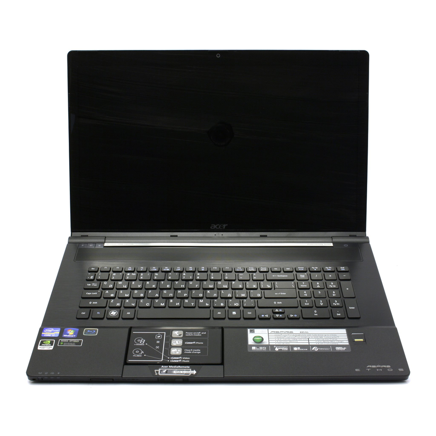
Notebook Tour Top View Figure 1-1. Top View Table 1-1. Top View Icon Acer Crystal Eye webcam Display screen Hardware Specifications and Configurations Item Web camera for video communication (only for certain models). Also called Liquid-Crystal Display (LCD), displays computer output (Configuration may vary by model). - Page 22 Turns the keyboard backlight on or off. For entering data into the computer. Touch-sensitive pointing device which functions like a computer mouse*. Touch sensitive controls for Acer clear.fi, volume (up, down) and media (play/ pause, previous, next, stop). * Touchpad becomes inactive when media console is active.
-
Page 23: Acer Mediaremote
Acer MediaRemote The detachable touchpad features a media console that allows the user to control Acer clear.fi and Windows Media Player. Figure 1-2. Acer MediaRemote To detach the touchpad, slide the touchpad release latch and lift the MediaRemote from the touchpad dock. - Page 24 Preparing the MediaRemote for use Before using the MediaRemote as a detachable device, ensure the battery is fully charged. The MediaRemote is already paired with the computer. Status light The status light (just above the Touchpad Mode button) indicates connection and battery status.
-
Page 25: Media Console
clear.fi shortcuts If the clear.fi shortcuts are active, you can easily open the media sections of clear.fi. the blank area of the touchpad can still be used as a pointing device. Table 1-4. clear.fi shortcuts Icon Select Main menu Video Music Media console Press the Touchpad Mode button again to activate the media console. - Page 26 G-sensor While the MediaRemote is detached, it may be rotated from the usual landscape orientation and used in a portrait mode. An internal g-sensor will change the orientation of the touchpad controls. If the touchpad controls do not match the orientation of the MediaRemote, tilt the MediaRemote (at least 30º) for a couple of seconds.
-
Page 27: Front View
Front View Figure 1-4. Front View Table 1-6. Front View Icon Communication key Multi-in-1 card reader Touchpad release latch Hardware Specifications and Configurations Item Enables/disables the computer’s communication devices. (Communication devices may vary by configuration.) Accepts Secure Digital (SD), MultiMediaCard (MMC), Memory Stick PRO (MS PRO), xD-Picture Card (xD). -
Page 28: Left View
Left View Figure 1-5. Left View Table 1-7. Left View Icon DC-IN jack Ventilation slots External display (VGA) port HDMI port USB 2.0 / 3.0 port USB 2.0 / e SATA port Line-in jack Microphone-in jack Headphones/speaker/ line-out jack with S/PDIF support. -
Page 29: Right View
Right View Figure 1-6. Right View Table 1-8. Right View Icon USB 2.0 ports Optical drive Optical drive eject button/optical disk access indicator Emergency eject hole Ethernet (RJ-45) port Kensington lock slot Hardware Specifications and Configurations Item Connect to USB 2.0 devices (e.g., USB mouse, USB camera). -
Page 30: Base View
Base View Figure 1-7. Base View Table 1-9. Base View Icon Sub woofer Memory compartment Hard disk bay Ventilation slots Battery release latch 1-20 Item Emits low frequency sound output. Houses the computer’s main memory. Houses the computer’s hard disk (secured with screws) Enable the computer to stay cool, even after prolonged use. -
Page 31: Touchpad Basics
Touchpad Basics Figure 1-8. Touchpad Move a finger across the Touchpad (1) to move the cursor. Press the right (2) and left(3) buttons located beneath the Touchpad to perform selection and execution functions. These two buttons are the equivalent of the left and right buttons on a mouse. -
Page 32: Using The Keyboard
Using the Keyboard Figure 1-9. Keyboard Lock Keys The keyboard has three lock keys which can be toggled on and off. (Table 1-11) Table 1-11. Keyboard Lock Keys Lock key Caps Lock When Caps Lock is on, all alphabetic characters typed are in uppercase. Num Lock When Num Lock is on, the embedded keypad is in numeric mode. -
Page 33: Windows Keys
Windows Keys The keyboard has two keys that perform Windows-specific functions. Windows Logo key Application key Table 1-13. Windows Keys Windows Logo Pressed alone, this key has the same effect as clicking on the Windows Start button; it launches the Start menu. It can also be used with other keys to provide a variety of functions. -
Page 34: Hotkeys
Hotkeys Hotkeys or key combinations can be used to access most of the computer's controls like screen brightness and volume output. Figure 1-10. Keyboard Hotkeys To activate hotkeys, press and hold the Fn key before pressing the other key in the hotkey combination. - Page 35 Table 1-14. Keyboard Hotkeys (Continued) Hotkey Icon <Fn> + < > <Fn> + < > <Fn> + < > <Fn> + < > <Fn> + <Home> <Fn> + <Pg Up> <Fn> + <Pg Dn> <Fn> + <End> Hardware Specifications and Configurations Function Brightness up...
-
Page 36: System Block Diagram
System Block Diagram 3/CLK2 port PCIe 5/CLK5 port PCIe Interfaces Graphics MEMORY SYSTEM Figure 1-11. System Block Diagram 1-26 Hardware Specifications and Configurations... -
Page 37: Specification Tables
Specification Tables Computer specifications Item Dimensions Length Width Height (front to rear) Weight (equipped with optical drive, flash drive, and battery) Input power Operating voltage Operating current Temperature Operating (not writing to optical disc) Operating (writing to optical disc) Nonoperating Relative humidity Operating Nonoperating... -
Page 38: System Board Major Chips
System Board Major Chips Item Core logic Intel VGA chip Nvidia N12P-GS/N12E-GE Realtek 8111E USB 2.0 Intel USB 3.0 NEC UPD720200AF1-DAP-A Super I/O controller Nuvoton NPCE791C Bluetooth Wireless PCMCIA Audio codec Realtek ALC669-GR 5.1 Card reader JMB388-QGAZ0A Processor Item... -
Page 39: Processor Specifications
Processor Specifications Item CPU Speed (GHz) i3-2310M i5-2410M i5-2540M I7-2620M CPU Fan True Value Table (Tj=100) CPU Temp Fan On = 45°C; Fan Off = 40°C Fan On = 55°C; Fan Off = 50°C Fan On = 78°C; Fan Off = 67°C Fan On = 84°C;... -
Page 40: Vga Fan True Value Table
VGA Fan True Value Table CPU Temp Fan On = 45°C; Fan Off = 40°C Fan On = 55°C; Fan Off = 50°C Fan On = 68°C; Fan Off = 60°C Fan On = 81°C; Fan Off = 73°C Fan On = 92°C; Fan Off = 86°C OS shut down at 105°C;... - Page 41 Slot 1 (MB) Slot 2 (MB) Memory Combinations (continued) 1024 1024 2048 2048 2048 2048 2048 2048 2048 2048 2048 2048 2048 2048 2048 2048 4096 4096 4096 4096 4096 4096 4096 4096 4096 4096 4096 4096 4096 4096 Hardware Specifications and Configurations Slot 3 (MB) Slot 4 (MB) 1024...
-
Page 42: Video Interface
Video Interface Item Chipset Package Interface Compatibility Sampling rate BIOS Item BIOS vendor BIOS Version BIOS ROM type BIOS ROM size Features 1-32 Specification NVidia N12P-GS/N12E-GE GB2-128/ GB3-128 PCIE X 16 ® They support Microsoft DirectX 11 with shader Model 5.0, PCI ®... -
Page 43: Lan Interface
Integrated switching regulator for improved power consumption Specification ACER AF7B_A10B GF7T keyboard US/UK 129 keys, JP 132 keys Plug USB keyboard to the USB port directly: Yes Support Application keys for Windows Vista / Windows 7 Multi-Langue support... -
Page 44: Hard Disk Drive (Avl Components)
Hard Disk Drive (AVL components) Item Vendor & Model Hitachi Name HTS545050B9A 300, WD5000BPVT- 22HXZT1 Capacity (GB) Bytes per sector Data heads 4, 3 Drive Format Disks Spindle speed (RPM) Performance Specifications Buffer size Interface Fast data transfer 3.0, 3.0 rate (Gbits / sec, max) Media data transfer... -
Page 45: Super-Multi Drive
Super-Multi Drive Item Vendor & Model name Performance Specification Transfer rate (KB/sec) Buffer Memory Interface Applicable disc format Loading mechanism Power Requirement Input Voltage Hardware Specifications and Configurations Specification TSST TS-L633F With CD Diskette Sustained: Max 3.6 (24x) 1.5 MB SATA DVD: ... - Page 46 Item Super-Multi Drive (Continued) Item Vendor & Model name Performance Specification Transfer rate (KB/sec) Buffer Memory Interface Applicable disc format Loading mechanism Power Requirement Input Voltage 1-36 Specification Specification Panasonic UJ8A0 With CD Diskette Sustained: Max 3.6 (24x) SATA DVD: ...
-
Page 47: Bd Drive
BD Drive Items Vendor & Model HLDS CT30N name Performance With CD Diskette Specification Transfer rate Sustained: (KB/sec) 3600 KB/s (24x) max. Buffer Memory 2 MB Interface SATA Applicable disc format Loading mechanism Drawer type manual load / Electrical release Power Requirement Input Voltage 5V +/- 5%... -
Page 48: Led 18.4
LED 18.4” Item Vendor/Model name Screen Diagonal (mm) Active Area (mm) Display resolution (pixels) Pixel Pitch (mm) Typical White Luminance (cd/m ) also called Brightness Contrast Ratio Response Time (Optical Rise Time/Fall Time) msec Typical Power Consumption (watt) Weight (without inverter) Physical Size (mm) Electrical Interface Viewing Angle (degree) -
Page 49: Display Supported Resolution (Lcd)
Display Supported Resolution (LCD) Resolution 800x600p/60Hz 16:9 1024x768p/60Hz 16:9 1280x600/60Hz 16:9 1280x720/60Hz 16:9 1280x768/60Hz 16:9 1360x768/60Hz 16:9 1366x768/60Hz 16:9 Graphics Controller Item VGA Chip Supports Hardware Specifications and Configurations 8 bits 16 bits 32 bits Specification Nvidia N12P-GS/N12E-GE ® They support Microsoft DirectX 11 with shader Model 5.0, PCI ®... -
Page 50: Display Supported Resolution (Gpu)
Display Supported Resolution (GPU) Resolution 800x600p/60Hz 16:9 1024x768p/60Hz 16:9 1280x600/60Hz 16:9 1280x720/60Hz 16:9 1280x768/60Hz 16:9 1360x768/60Hz 16:9 1366x768/60Hz 16:9 Bluetooth Interface Item Chipset Foxconn Bluetooth BRM 2070, Data throughput Protocol 2.1 + EDR Interface USB 2.0 Connector type SM06B-XSRK-E Supported protocol 1-40 8 bits 16 bits... -
Page 51: Bluetooth Module
Bluetooth Module Item Controller Foxconn Bluetooth BRM 2070 Features Bluetooth 3.0 compliant Point-to-multipoint operation External USB interface for data Onboard antenna and SMA RF connector Coexistence support Item Controller Foxconn Bluetooth ATH BU12 Features Single-chip Bluetooth v2.1/3.0+EDR integrated solution ... -
Page 52: Audio Codec And Amplifier
Audio Codec and Amplifier Item Audio Controller Features 1-42 Specification Realtek ALC669X-GR Meets Microsoft WLP (Windows Logo Program) audio requirements High performance DACs with digital >110dB and analog 98dB (A-weighting) signal-to-noise High performance ADCs with digital > 100dB and analog ... -
Page 53: Audio Interface
Item Audio Codec and Amplifier (continued) Features Amplifier Audio Interface Item Audio Controller Audio onboard or optional Mono or Stereo Compatibility Sampling rate Internal microphone Internal speaker/quantity Wireless Module 802.11b/g/n Item Chipset Data throughput Protocol Interface Battery Item Vendor & Model name Battery Type Pack capacity Number of battery cell... -
Page 54: Vram
VRAM Item Chipset Memory size Interface USB Port Item USB compliance level EHCI Number of USB port(s) Location Output Current HDMI Port Item Compliance level Data throughput Number of HDMI port(s) Location AC Adapter Item Input rating Maximum input AC current Inrush current Efficiency 1-44... -
Page 55: System Power Management
System Power Management Item Mech. Off (G3) Soft Off (G2/S5) Working (G0/S0) Suspend to RAM (S3) Save to Disk (S4) Card Reader Item Chipset Package Maximum supported size Features Hardware Specifications and Configurations Specification Al devices in the system are turned off completely. OS initiated shutdown. -
Page 56: System Led Indicator
Item Card Reader (continued) Features System LED Indicator Item Lock System state HDD access state Wireless state Power button backlight Battery state 1-46 Specification Compliant with Memory Stick XC Micro Format Specification ver.1.00-00 Compliant with Memory Stick XC-HG Micro Format ... -
Page 57: System Dma Specification
System DMA Specification Legacy Mode DMA0 DMA1 DMA2 DMA3 DMA4 DMA5 DMA6 DMA7 *ExpressCard controller can use DMA 1, 2, or 5. System Interrupt Specification Hardware IRQ IRQ0 IRQ1 IRQ2 IRQ3 IRQ4* IRQ5* IRQ6 IRQ7* IRQ8 IRQ9* IRQ10* IRQ11* IRQ12 IRQ13 IRQ14* IRQ15*... -
Page 58: System Io Address Map
System IO Address Map I/O address (hex) 000 - CF7 PCI bus 000 - 01F Direct memory access controller 020 - 021 Programmable interrupt controller 024 - 025 Programmable interrupt controller 028 - 029 Programmable interrupt controller 02C - 02D Programmable interrupt controller 02E - 02F Motherboard resources... - Page 59 I/O address (hex) 0B0 - 0B1 Programmable interrupt controller 0B2 - 0B3 Motherboard resources 0B4 - 0B5 Programmable interrupt controller 0B8 - 0B9 Programmable interrupt controller 0BC - 0BD Programmable interrupt controller 0C0 - 0DF Direct memory access controller Numeric data processor 3B0 - 3BB Intel 3C0 - 3DF...
- Page 60 I/O address (hex) 7080-7087 Standard AHCI 1.0 Serial ATA Controller 7088-708F Standard AHCI 1.0 Serial ATA Controller 7090-7093 Standard AHCI 1.0 Serial ATA Controller 7094-7097 Standard AHCI 1.0 Serial ATA Controller FFFF Motherboard resources 1-50 System Function (shipping configuration) Hardware Specifications and Configurations...
-
Page 61: System I/O Address Specifications
System I/O Address Specifications I/O address (hex) System Function (shipping configuration) 220 - 22F 230 - 26D 26E - 26 278 - 27F 280 - 2AB 2A0 - 2A7 2A8 - 2E7 2E8 - 2EF 2F0 - 2F7 2F8 - 2FF 300 - 31F 320 - 36F 370 - 377... - Page 62 1-52 Hardware Specifications and Configurations...
- Page 63 CHAPTER System Utilities...
- Page 64 BIOS Setup Utility........2-3 Navigating the BIOS Utility .
-
Page 65: Bios Setup Utility
System Utilities BIOS Setup Utility This utility is a hardware configuration program built into a computer’s BIOS (Basic Input/Output System). The utility is pre-configured and optimized so most users do not need to run it. If configuration problems occur, the setup utility may need to be run. Refer to arises. -
Page 66: Bios
BIOS The following is a description of the tabs found on the InsydeH20 BIOS Setup Utility screen: NOTE: NOTE: The screens provided are for reference only. Actual values may differ by model. Information Information Main CPU Type: CPU Speed: HDD Model Name: HDD Serial Number: ATAPI Model Name: System BIOS Version:... - Page 67 Table 2-1. BIOS Information Parameter CPU Type CPU Speed HDD0 Model Name HDD0 Serial Number ATAPI Model Name System BIOS Version VGA BIOS Version Serial Number Asset Tag Number Product Name UUID System Utilities Description CPU (central processing unit) type and speed of system Speed of the CPU Model name of HDD0 (hard disk drive) installed on primary IDE master...
-
Page 68: Main
Main The Main tab allows the user to set system time and date, enable or disable boot option and enable or disable recovery. Information Main System Time System Date Total Video Memory: Video Memory: Quiet Boot Network Boot F12 Boot Menu D2D Recovery SATA Mode ... - Page 69 Table 2-2. BIOS Main (Continued) Parameter Network Option to boot system from LAN (local area network) Boot F12 Boot Option to use boot menu during POST Menu Option to use D2D Recovery function Recovery SATA Mode Option to set SATA controller mode System Utilities Description Format/Option...
-
Page 70: Security
Security The Security tab shows parameters that safeguard and protect the computer from unauthorized use. Information Main Supervisor Password Is: User Password Is: HDD Password Is: Set Supervisor Password Set User Password Set HDD Password Password on Boot Help ... -
Page 71: Setting A Password
Table 2-3. BIOS Security (Continued) Parameter Password on Boot NOTE: NOTE: When prompted to enter password, three attempts are allowed before system halts. Resetting BIOS password may require computer be returned to dealer. Password on Boot must be set to Enabled to activate password feature. Passwords are not case sensitive. - Page 72 IMPORTANT: Use care when typing a password. Characters do not appear on the screen. 3. Retype password in the Confirm New Password field and press Enter. 4. If new password and confirm new password strings match, the Setup Notice dialog screen is shown (Figure 2-5).
-
Page 73: Removing A Password
Removing a Password Perform the following: 1. Use the and keys to highlight Set Supervisor Password and press Enter. The Set Supervisor Password dialog box is shown. (Figure 2-7) Figure 2-7. Removing a Password: Set Supervisor Password 2. Type current password in Enter Current Password field and press Enter. 3. - Page 74 a. Press Enter to return to the BIOS Setup Utility Security menu. b. The Supervisor Password parameter is shown as Set. c. Press F10 to save changes and exit BIOS Setup Utility. 6. If current password and new password strings do not match, the Setup Warning dialog is shown (Figure 2-10).
-
Page 75: Boot
Boot The Boot tab allows changes to the order of boot devices used to load the operating system. Bootable devices include the: USB diskette drives Onboard hard disk drive DVD drive in the module bay Use and keys to select a device and press F5 or F6 to change the value. Information Main Boot priority order:... -
Page 76: Exit
Exit The Exit tab allows users to save or discard changes and quit the BIOS Setup Utility. Information Main Exit Saving Changes Exit Discard Changes Load Setup Defaults Discard Changes Save Changes Help Exit Figure 2-13. BIOS Exit Table 2-4 describes the parameters in Figure 2-13. -
Page 77: Bios Flash Utilities
BIOS Flash Utilities BIOS Flash memory updates are required for the following conditions: New versions of system programs New features or options Restore a BIOS when it becomes corrupted. Use the Flash utility to update the system BIOS Flash ROM. NOTE: NOTE: If a Crisis Recovery Disc is not available, create one before BIOS Flash utility is used. -
Page 78: Dos Flash Utility
DOS Flash Utility Perform the following to use the DOS Flash Utility: 1. Press F2 during boot to enter Setup Menu. 2. Select Boot Menu to modify boot priority order. 3. Move USB HDD to position 1 (Figure 2-14). (Refer to Information Main Boot priority order:... - Page 79 BIOS flash process begins. (Figure 2-16) Figure 2-16. Updating Flash ROM Blocks 7. Flash is complete when the message, Flash Programming Complete is shown. System will restart automatically when finished. NOTE: NOTE: If AC power is not connected, the following message is shown (Figure 2-17). Plug in the AC power to continue.
-
Page 80: Winflash Utility
WinFlash Utility Perform the following to use the WinFlash Utility: 1. Double click the WinFlash executable. 2. Click OK to begin the update. A progress screen is shown. (Figure 2-18) V0.05 V0.08 Figure 2-18. InsydeFlash NOTE: NOTE: If the error message appears, check the system BIOS ROM-file size. 2-18 System Utilities... -
Page 81: Hdd/Bios Password Utilities
HDD/BIOS Password Utilities CAUTION: If Power-on Password authentication is enabled, the BIOS password can only be cleared by initiating the Crisis Disk Recovery procedure. See Crisis Disk. Clearing HDD Passwords This section provides details about removing an HDD password from the BIOS. If the HDD password is incorrectly entered three times, an error is generated. - Page 82 NOTE: NOTE: A key code is generated for use with unlocking utility. Make note of this code. 3. On a separate, compatible device, boot to DOS. 4. Execute UnlockHD.exe (Figure 2-22) to create a password unlock code. Use the format <UnlockHD [key code]>...
-
Page 83: Clearing Bios Passwords
Clearing BIOS Passwords If a BIOS password (Supervisor Password and/or User Password) is set, the BIOS will prompt for the password at system POST or upon entering the BIOS setup menu. There are two methods for clearing the BIOS password. A hardware method and a software method. Hardware Method 1. - Page 84 Software Method If wrong supervisor password is entered three times, the System will halt! dialog is shown. (Figure 2-25) Figure 2-25. Supervisor Password Error 1. At a DOS prompt, enter ClearSuPw.exe. (Figure 2-26) Figure 2-26. Clear Supervisor Password Utility 2. When message Clear the SU Pws completely is shown, supervisor password has been removed.
-
Page 85: Miscellaneous Tools
Miscellaneous Tools Using Boot Sequence Selector The Boot Sequence Selector allows the boot order to be changed without accessing the BIOS Setup Utility. To use the Boot Sequence Selector, perform the following steps: 1. Boot to DOS. 2. At a DOS prompt, enter bs <#> and a boot sequence ID number. A boot sequence ID is a digit from 1 to 4. -
Page 86: Using Dmi Tools
Using DMI Tools The DMI (Desktop Management Interface) Tool copies BIOS information to EEPROM. Used in the DMI pool for hardware management. When the BIOS shows Verifying DMI pool data, it is checking that the table correlates with the hardware before sending it to the operating system (Windows, etc.). To update the DMI Pool, perform the following: 1. - Page 87 3. Press 1 to modify asset tag key. (Figure 2-29) Figure 2-29. Asset Tag Menu Item 4. Press 2 to modify the product number key. (Figure 2-30) Figure 2-30. Product Name Menu Item System Utilities 2-25...
- Page 88 5. Press 3 to modify serial number key. Figure 2-31. Serial Number Menu Item 6. Press 4 to modify the 1394 GUID number key. Figure 2-32. 1394 GUID Number Menu Item 2-26 System Utilities...
- Page 89 7. Press 0 to exit. Figure 2-33. Exit Menu Item 8. At the command prompt, type VEEPROM to write any changes in the data to the EEPROM. Figure 2-34. VEEPROM Command Prompt NOTE: NOTE: When using any of the write options, restart the system to make the new DMI data effective.
-
Page 90: Using The Lan Mac Eeprom Utility
Using the LAN MAC EEPROM Utility Use MAC.BAT utility to write the MAC.CFG file to EEPROM under DOS mode. 1. Use a text editor (e.g. Notepad) to open and edit the MAC.CFG file. (Figure 2-35) File Title= MAC Address byte WriteData=’001122334455’... - Page 91 2-29 System Utilities...
- Page 92 2-30 System Utilities...
- Page 93 CHAPTER Maintenance Procedures...
- Page 94 Introduction ......... 3-5 General Information .
- Page 95 PCH Heatsink Removal ......3-49 PCH Heatsink Installation......3-49 RTC Battery Removal .
-
Page 97: Introduction
Machine Maintenance Procedures Introduction This chapter contains general information about the notebook, a list of tools needed to perform the required maintenance and step by step procedures on how to remove and install components from the notebook computer. General Information The product previews seen in the following procedures may not represent the final product color or configuration. -
Page 98: Maintenance Flowchart
Maintenance Flowchart The flowchart in Figure 3-1 provides a graphic representation of the module removal and installation sequences. It provides information on what components need to be removed and installed during servicing. Figure 3-1. Maintenance Flow Machine Maintenance Procedures... -
Page 99: Getting Started
Getting Started The flowchart (Figure 3-1) identifies sections illustrating the entire removal and install sequence. Observe the order of the sequence to avoid damage to any of the hardware components. Perform the following prior to performing any maintenance procedures: 1. Remove external power (A) from the system. (Figure 3-2) 2. -
Page 100: Dummy Card Removal
Dummy Card Removal 1. Push in dummy card (A) to release from spring latch. (Figure 3-4) 2. Remove dummy card. Figure 3-4. Dummy Card Dummy Card Installation 1. Insert dummy card (A). (Figure 3-4) 2. Push card until spring latch locks. Machine Maintenance Procedures... -
Page 101: Logic Door Removal
Logic Door Removal 1. Remove screws (A) from lower cover. (Figure 3-5) Figure 3-5. Logic Door 2. Lift logic door from slot (B) on lower cover. 3. Remove logic door. Logic Door Installation 1. Align logic door flanges into slots (C) on lower cover. (Figure 3-6) Figure 3-6. - Page 102 2. Install and secure screws (A) to lower cover. (Figure 3-5) Size Quantity Screw Type M2.5x4.0 3-10 Machine Maintenance Procedures...
-
Page 103: Battery Cable Removal
Battery Cable Removal Prerequisite: Logic Door Removal 1. Locate battery cable (A) on mainboard. (Figure 3-7) Figure 3-7. Lower Cover Overview 2. Disconnect battery cable (A) from mainboard connector (F). Battery Cable Installation 1. Connect battery cable (A) to mainboard connector (F). (Figure 3-7) 2. -
Page 104: Lower Cover Dimm Module Removal
Lower Cover DIMM Module Removal Prerequisite: Battery Cable Removal 1. Locate DIMM (Dual In-Line Memory Module) module (B) on lower cover. 2. Open module clips (A) to unlock module. (Figure 3-8) Figure 3-8. DIMM Module(s) in Lower Cover 3. Disconnect DIMM module (B) from mainboard connector (D). 4. -
Page 105: Main Hdd (Hard Disk Drive) Module Removal
Main HDD (Hard Disk Drive) Module Removal Prerequisite: Battery Cable Removal 1. Locate main HDD module (C) on lower cover. CAUTION: HDD module is connected to mainboard. Use caution when removing module. 2. Use mylar tabs (A) to lift HDD module until HDD cable clears lower cover. (Figure 3-9) Figure 3-9. -
Page 106: Hdd Brackets Removal
HDD Brackets Removal Prerequisite: Main HDD (Hard Disk Drive) Module Removal (as required for Secondary HDD) 1. Remove screws (A) from HDD brackets. (Figure 3-10) Figure 3-10. HDD Module Brackets 2. Remove HDD brackets (B) from HDD module. HDD Brackets Installation 1. -
Page 107: Wlan Module Removal
WLAN Module Removal Prerequisite: Battery Cable Removal 1. Locate WLAN (Wireless Local Area Network) module (E) on mainboard. 2. Disconnect WLAN main (A) and auxiliary (B) antenna cables from WLAN module connectors (F). (Figure 3-11) Figure 3-11. WLAN Module 3. Remove screw (C) from mainboard. 4. -
Page 108: Touchpad Removal
Touchpad Removal Prerequisite: Battery Cable Removal 1. Locate touchpad removal switch (A). (Figure 3-12) Figure 3-12. Touchpad Removal Switch 2. Move and hold switch as shown in Figure 3-13. Figure 3-13. Removing Touchpad 3. Remove touchpad. 3-16 Machine Maintenance Procedures... -
Page 109: Touchpad Installation
Touchpad Installation 1. Locate mainboard connector (A) in touchpad bay. (Figure 3-14) Figure 3-14. Touchpad Installation 2. Connect touchpad (B) to mainboard connector. 3. Install logic door. 3-17 Machine Maintenance Procedures... -
Page 110: Odd (Optical Disk Drive) Module Removal
ODD (Optical Disk Drive) Module Removal Prerequisite: Main HDD (Hard Disk Drive) Module Removal (Must remove Secondary HDD. Procedure is shown in Main HDD removal) 1. Locate ODD cable (A) on mainboard. (Figure 3-15) 2. Disconnect ODD cable from mainboard connector (B). Figure 3-15. - Page 111 7. Press ODD tray release button (F) on ODD bezel to eject ODD tray. (Figure 3-17) Figure 3-17. ODD Eject Button 8. Slide ODD tray (F) from ODD module. (Figure 3-18) Figure 3-18. ODD Bezel Removal 9. Unlock latch (G) to separate ODD bezel (H) from tray. (Figure 3-19) Figure 3-19.
-
Page 112: Odd Module Installation
11. Remove screws (J) from ODD bracket (K). (Figure 3-20) Figure 3-20. ODD Bracket 12. Remove ODD bracket. ODD Module Installation 1. Install ODD bracket (K) to ODD module. (Figure 3-20) 2. Install and secure screws (J) from ODD bracket to ODD module. 3. -
Page 113: Keyboard Assembly Removal
Keyboard Assembly Removal Prerequisite: Touchpad Removal ODD (Optical Disk Drive) Module Removal Main HDD (Hard Disk Drive) Module Removal Lower Cover DIMM Module Removal 1. Remove screws (A) and (B) from lower cover. (Figure 3-21) Figure 3-21. Lower Cover Screws 2. - Page 114 NOTE: NOTE: Cover LCD panel with cloth or sheet to protect LCD panel. 3. Turn computer and open cover to show top edge of keyboard assembly. (Figure 3-22) Figure 3-22. Top of Keyboard Assembly. CAUTION: Keyboard assembly is connected to upper cover. Use caution when removing. 4.
- Page 115 CAUTION: Keyboard FPC and LED keyboard backlight cable are connected to mainboard. Use caution when removing keyboard assembly. 6. Turn keyboard assembly as shown in Figure 3-24. Figure 3-24. Keyboard Assembly Flipped Over 7. Disconnect keyboard FPC (E) from mainboard connector. 8.
-
Page 116: Keyboard Assembly Installation
Keyboard Assembly Installation 1. Turn keyboard assembly as shown in 2. Connect keyboard LED backlight cable (F) to mainboard connector. 3. Connect keyboard FPC (E) to mainboard connector. 4. Locate keyboard assembly flanges (G). (Figure 3-25) Figure 3-25. Keyboard Assembly Flanges 5. - Page 117 6. Install keyboard assembly flush against the upper cover. 7. Press along edge of keyboard assembly until secure with upper cover. 8. Turn computer over to show bottom of lower cover. 9. Install and secure screws (C) in ODD bay to lower cover. 10.
-
Page 118: Keyboard Removal
Keyboard Removal Prerequisite: Keyboard Assembly Removal 1. Remove screws (A) from keyboard assembly. (Figure 3-27) Figure 3-27. Bottom Side of Keyboard Assembly 2. Remove left (B) and right (C) brackets from keyboard. 3. Remove keyboard from upper cover. 3-26 Machine Maintenance Procedures... -
Page 119: Keyboard Installation
Keyboard Installation 1. Locate guides (D) on keyboard assembly. (Figure 3-28) Figure 3-28. Inserting Keyboard into Guides 2. Insert keyboard into guides. 3. Align left (B) and right (C) brackets on keyboard. (Figure 3-27) 4. Install and secure screws (A) to keyboard assembly. 5. -
Page 120: Function Board Removal
Function Board Removal Prerequisite: Keyboard Assembly Removal 1. Locate function board (A) on upper cover. (Figure 3-29) Figure 3-29. Upper Cover Overview 2. Disconnect function board FFC (D) from function board connector (E). (Figure 3-30) Figure 3-30. Function Board 3-28 Machine Maintenance Procedures... -
Page 121: Function Board Installation
3. Remove screw (F) from upper cover. 4. Remove function board (A) from guidepins (G) on upper cover. Function Board Installation 1. Align function board (A) with guidepins (G). 2. Install function board on upper cover. 3. Install and secure screw (F) to upper cover. 4. -
Page 122: Upper Cover Dimm Module Removal
Upper Cover DIMM Module Removal Prerequisite: Keyboard Assembly Removal 1. Locate DIMM module bracket (B) on lower cover. 2. Remove screw (A) and DIMM module bracket from upper cover. (Figure 3-31) Figure 3-31. DIMM Module Screw 3. Open module clips (C). (Figure 3-32) Figure 3-32. -
Page 123: Upper Cover Dimm Module Installation
4. Disconnect DIMM module (D) from mainboard connector (E). 5. Repeat steps 2 and 3 for remaining DIMM module. Upper Cover DIMM Module Installation 1. Connect DIMM module (D) to mainboard connector (E). (Figure 3-32) 2. Press on module until clips (C) lock into place. 3. -
Page 124: Power Board Removal
Power Board Removal Prerequisite: Keyboard Assembly Removal NOTE: NOTE: Power board and RJ45 connector are located on same board. 1. Locate power board (C) on lower cover. 2. Disconnect power board FFC (A) from mainboard connector (B). (Figure 3-31) Figure 3-34. LAN Board 3. -
Page 125: Upper Cover Removal
Upper Cover Removal Prerequisite: Function Board Removal Upper Cover DIMM Module Removal Power Board Removal 1. Disconnect LVDS cable (A) from mainboard connector (B). (Figure 3-35) Figure 3-35. Upper Cover 2. Disconnect microphone cable (C) from mainboard connector (D). 3. Remove LVDS cable from guides (F). 4. - Page 126 5. Route WLAN main and auxiliary cables (G) through lower cover opening (H). (Figure 3-36) Figure 3-36. WLAN Cables on Lower Cover 6. Turn computer to show upper cover. 7. Remove WLAN main and auxiliary cables (G) from guides (J). (Figure 3-37) Figure 3-37.
- Page 127 8. Disconnect function board FFC (K) from mainboard connector (L). (Figure 3-38) Figure 3-38. Upper Cover FFC Connections 9. Disconnect LAN board FFC (M) from mainboard connector (N). 10. Disconnect fingerprint scanner FFC (P) from mainboard connector (Q). 11. Remove screws (R) from lower cover. (Figure 3-39) Figure 3-39.
- Page 128 CAUTION: Touchpad connector extends out from upper cover. Use caution when removing upper cover. 12. Lift side (S) of upper cover until separated from lower cover. (Figure 3-40) Figure 3-40. Lifting Upper Cover to Clear Touchpad Connector 13. Rotate upper cover until opening clears touchpad connector (U). 14.
-
Page 129: Upper Cover Installation
Upper Cover Installation 1. Install side (T) of upper cover until secure to latch (V) on lower cover. (Figure 3-42) Figure 3-42. Installing Upper Cover Latch 2. Install upper cover so touchpad connector (U) is inserted through opening in upper cover. (Figure 3-40) 3. - Page 130 Size Quantity Screw Type M2.5x4.0 3-38 Machine Maintenance Procedures...
-
Page 131: Fingerprint Scanner Removal
Fingerprint Scanner Removal Prerequisite: Upper Cover Removal 1. Locate fingerprint scanner board (A) on bottom side of upper cover. (Figure 3-43) Figure 3-43. Fingerprint Scanner 2. Disconnect fingerprint scanner FFC (B) from fingerprint scanner connector (C). 3. Remove screw (D) securing bracket to upper cover. 4. -
Page 132: Fingerprint Scanner Installation
5. Remove fingerprint scanner from upper cover. Fingerprint Scanner Installation 1. Align and install fingerprint scanner module (A) to guidepin (G) on upper cover. (Figure 3-43) 2. Install fingerprint scanner bracket (E) to latch (F) and guidepin (G) on upper cover. (Figure 3-44) 3. -
Page 133: Bluetooth Module Removal
Bluetooth Module Removal Prerequisite: Upper Cover Removal 1. Locate Bluetooth module (A) on lower cover. (Figure 3-45) Figure 3-45. Lower Cover Overview 2. Remove Bluetooth module and adhesive from lower cover. 3. Disconnect Bluetooth cable (D) from Bluetooth module connector. (Figure 3-46) Figure 3-46. -
Page 134: Bluetooth Module Installation
Bluetooth Module Installation 1. Install adhesive (E) to Bluetooth module. (Figure 3-46) 2. Connect Bluetooth cable (D) to Bluetooth module connector. 3. Install Bluetooth module (A) to lower cover. (Figure 3-45) 4. Install upper cover. 3-42 Machine Maintenance Procedures... -
Page 135: Usb Board Removal
USB Board Removal Prerequisite: Upper Cover Removal 1. Locate USB board (B) on lower cover. 2. Disconnect USB FFC (A) from USB board connector (C). (Figure 3-47) Figure 3-47. USB Board 3. Remove screw (D) from lower cover. 4. Lift USB board tab (E) until clear of guidepin (F). (Figure 3-48) Figure 3-48. -
Page 136: Usb Board Installation
USB Board Installation 1. Align and install USB ports (G) to USB port slots on lower cover. (Figure 3-48) 2. Align USB board to guidepin (F). 3. Install USB board on lower cover. 4. Install screw (D) to lower cover. (Figure 3-47) 5. -
Page 137: Dt Module Removal
DT Module Removal Prerequisite: Upper Cover Removal 1. Locate DT module (C) on lower cover. (Figure 3-45) 2. Disconnect DT cable (A) from DT module connector (B). (Figure 3-49) Figure 3-49. DT Module 3. Remove screw (D) from lower cover. 4. -
Page 138: Mainboard Removal
Mainboard Removal Prerequisite: Upper Cover Removal 1. Disconnect DT cable (A) from mainboard connector (B). (Figure 3-50) Figure 3-50. Mainboard Connectors 2. Remove DT cable from guide (C). 3. Disconnect Bluetooth cable (D) from mainboard connector (E). 4. Disconnect USB board FFC (F) from mainboard connector (G). 5. - Page 139 7. Remove screws (M) from lower cover. (Figure 3-51) Figure 3-51. Mainboard Screws CAUTION: Use caution when installing mainboard. Forced installation may damage left side connectors. CAUTION: After mainboard removal, use caution not to damage touchpad connector 8. Lift mainboard from side (N) until clear of bottom speaker module (Q). (Figure 3-52) Figure 3-52.
-
Page 140: Mainboard Installation
Mainboard Installation CAUTION: Use caution when installing mainboard. Forced installation may damage left side connectors. NOTE: NOTE: Make sure all cables are clear from mainboard during installation. 1. Install mainboard by sliding side (P) at a slight angle into slots on lower cover. (Figure 3-52) 2. -
Page 141: Pch Heatsink Removal
PCH Heatsink Removal Prerequisite: Mainboard Removal 1. Locate heatsink (A) on mainboard. (Figure 3-53) Figure 3-53. Heatsink 2. Remove screws (B) from lower cover. 3. Remove heatsink from mainboard. PCH Heatsink Installation 1. Install heatsink to mainboard (Figure 3-53) 2. Install and secure screws (B) to lower cover. 3. -
Page 142: Rtc Battery Removal
RTC Battery Removal Prerequisite: Mainboard Removal 1. Locate RTC battery (A) on mainboard. (Figure 3-54) Figure 3-54. RTC Battery Removal. 2. Remove RTC battery from RTC battery holder (B). IMPORTANT: Follow local regulations for battery disposal. RTC Battery Installation 1. Install RTC battery (A) to RTC battery holder (B). (Figure 3-54) 2. -
Page 143: Thermal Assembly Removal
Thermal Assembly Removal Prerequisite: Mainboard Removal 1. Locate thermal assembly (A) on mainboard. (Figure 3-55) 2. Disconnect fan cable (B) from mainboard connector. Figure 3-55. Thermal Assembly 3. Loosen captive screws (C1 - C7) on thermal assembly. (Figure 3-55) 4. Remove thermal assembly from mainboard. 3-51 Machine Maintenance Procedures... -
Page 144: Thermal Assembly Installation
Thermal Assembly Installation IMPORTANT: Apply approved thermal grease and make sure all heat pads are in place before replacing module CAUTION: Thermal grease can damage mainboard. Use caution when applying. The following thermal grease types are approved for use: PSX-D 1. -
Page 145: Cpu Removal
CPU Removal Prerequisite: Thermal Assembly Removal 1. Locate CPU module (A) on mainboard. (Figure 3-57) Figure 3-57. CPU in Socket 2. Turn captive screw (B) left 180º to release module. 3. Remove CPU module from socket. CPU Installation 1. Align CPU marker (C) with socket marker (D) and install CPU (A) in socket. (Figure 3-57) 2. - Page 146 Figure 3-58. Mainboard Recycling IMPORTANT: Follow local regulations for circuit board disposal. 3-54 Machine Maintenance Procedures...
-
Page 147: Lcd (Liquid Crystal Display) Module Removal
LCD (Liquid Crystal Display) Module Removal Prerequisite: Upper Cover Removal 1. Locate LCD module on upper cover. 2. Remove screws (A) from LCD hinges on lower cover. Figure 3-59. LCD Module 3. Lift and remove LCD module from lower cover guidepins (B). LCD Module Installation 1. -
Page 148: Speaker Module Removal
Speaker Module Removal Prerequisite: Mainboard Removal 1. Locate bottom speaker assembly (A) on lower cover. (Figure 3-60) Figure 3-60. Bottom Speaker Assembly 2. Remove screw (B) on bottom right speaker. 3. Remove bottom speaker assembly cable (C) from lower cover guides. 4. -
Page 149: Speaker Module Installation
Speaker Module Installation 1. Align and install upper speaker assembly (D) to guidepin (G) on lower cover. 2. Install upper speaker assembly cable (F) to guides. 3. Install and secure screws (E) to lower cover. 4. Install bottom speaker assembly (A) to lower cover. 5. -
Page 150: Battery Removal
Battery Removal Prerequisite: Speaker Module Removal 1. Locate battery cable (A) in lower cover. (Figure 3-62) Figure 3-62. Battery Cable 2. Push battery cable through lower cover slot (B). 3. Remove battery (C) from lower cover. Battery Installation 1. Install battery (C) on lower cover. (Figure 3-62) 2. -
Page 151: Dc-In Cable Removal
DC-IN Cable Removal Prerequisite: Speaker Module Removal 1. Locate DC-IN cable (A) on lower cover. (Figure 3-63) Figure 3-63. DC-IN cable 2. Remove DC-IN cable from guides on lower cover. 3. Remove DC-IN cable connector (B) from lower cover. DC-IN Cable Installation 1. - Page 152 3-60 Machine Maintenance Procedures...
- Page 153 CHAPTER Troubleshooting...
- Page 154 Introduction ......... 4-3 General Information .
-
Page 155: Introduction
NOTE: NOTE: The diagnostic tests are intended for Acer products only. Non-Acer products, prototype cards, or modified options can give false errors and invalid system responses. 1. Obtain as much detailed information as possible about the problem. -
Page 156: Power On Issues
Power On Issues If the system doesn’t power on, perform the following: Figure 4-1. Power On Issue Computer Shuts Down Intermittently If the system powers off at intervals, perform the following: 1. Makes sure the power cable is properly connected to the computer and the electrical outlet. -
Page 157: No Display Issues
No Display Issues If the Display fails, perform the following: Figure 4-2. No Display Issue No POST or Video If the POST or video does not appear, perform the following: 1. Make sure that internal display is selected. Switching between internal and external by pressing Fn+F5. -
Page 158: Abnormal Video
Remove any memory cards and CD/DVD discs. 8. Start the computer. If the computer boots correctly, add the devices one by one until the failure point is discovered. 9. Reseat the memory modules. 10. Remove the drives (refer to 11. If the Issue is still not resolved, refer to Abnormal Video If the video appears abnormal, perform the following: 1. -
Page 159: Lcd Failure
LCD Failure If the LCD fails, perform the following: Figure 4-3. LCD Failure Troubleshooting... -
Page 160: Keyboard Failure
Keyboard Failure If the Keyboard fails, perform the following: Figure 4-4. Keyboard Failure Troubleshooting... -
Page 161: Touchpad Failure
Touchpad Failure If the Touchpad fails, perform the following: Figure 4-5. Touchpad Failure Troubleshooting... -
Page 162: Internal Speaker Failure
Internal Speaker Failure If internal Speakers fail, perform the following: Figure 4-6. Internal Speaker Failure Sound Problems Perform the following: 1. Boot the computer. 2. Navigate to Start Manager. Check the Device Manager to determine that: The device is properly installed ... - Page 163 Drag the slider to 50. Confirm that the volume is not muted. Click Mixer to verify that other audio applications are set to 50 and not muted. 6. Navigate to Start Speakers are selected as the default audio device (green check mark). NOTE: NOTE: If Speakers does not show, right-click on the Playback tab and select Show...
-
Page 164: Microphone Failure
Microphone Failure If internal or external Microphones fail, perform the following: Figure 4-7. Microphone Failure 1. Check that the microphone is enabled. Navigate to Start and Sound Sound and select the Recording tab. 2. Right click on the Recording tab and select Show Disabled Devices (clear by default). -
Page 165: Usb Failure
USB Failure If the USB fails, perform the following: Figure 4-8. USB Failure 4-13 Troubleshooting... -
Page 166: Other Functions Failure
Other Functions Failure HDD Not Operating Correctly If the HDD fails to operate correctly, perform the following: 1. Disconnect all external devices. 2. Run a complete virus scan using up-to-date software to confirm the computer is virus free. 3. Run the Windows Vista Startup Repair Utility: a. -
Page 167: Odd Failure
ODD Failure If the ODD fails, perform the following: Figure 4-9. ODD Failure ODD Not Operating Correctly If the ODD exhibits any of the following symptoms it may be faulty: Audio CDs do not play when loaded DVDs do not play when loaded ... - Page 168 2. Use an different disc. 3. Navigate to Start with Removable Storage panel. 4. Navigate to Start Manager. 5. Double click lDE ATA/ATAPI controllers. If a device shows a down arrow, right click on the device and click Enable. 6.
- Page 169 6. Confirm that the default drive is record enabled: Navigate to Start Select the Recording tab. In the Desktop disc recording panel, select the writable ODD from the drop down list. Click OK. 7. Confirm that the software used for burning discs is the factory default. If using different software, refer to the software's user manual.
- Page 170 Playback is Choppy If playback is choppy or jumps, perform the following: 1. Check that system resources are not running low: Close some applications. Reboot and try the operation again. 2. Check that the ODD controller transfer mode is set to DMA. ...
-
Page 171: Random Loss Of Bios Settings
Try a different cable. If the drive works with the new cable, the original cable should be replaced. 4. Replace the ODD. Refer to Random Loss of BIOS Settings If the computer is experiencing intermittent loss of BIOS information, perform the following: 1. -
Page 172: External Mouse Failure
External Mouse Failure If an external Mouse fails, perform the following: 1. Use a different mouse. 2. If the mouse uses a wireless connection, insert new batteries and confirm there is a good connection. Refer to the mouse user manual. 3. -
Page 173: Intermittent Problems
1. Remove power from the computer. 2. Visually check them for damage. If any problems are found, replace the FRU. 3. Remove or disconnect all of the following devices: Non-Acer devices Printer, mouse, and other external devices ... -
Page 174: Post Codes
Post Codes The following are the InsydeH2O™ Functionality POST code tables. The components of the POST code table includes: SEC phase, PEI phase, DXE phase, BDS phase, CSM functions, S3 functions and ACPI functions. Phase PostBDS InsydeH2ODDT™ Reserve OEM Reserve Reserved Functionality Name (Include\PostCode.h) - Page 175 Functionality Name (Include\PostCode.h) SEC_GO_TO_PEICORE party relate functions – Platform dependence. Functionality Name (Include\PostCode.h) PEI_SIO_INIT PEI_CPU_REG_INIT PEI_CPU_AP_INIT* PEI_CPU_HT_RESET* PEI_PCIE_MMIO_INIT PEI_NB_REG_INIT PEI_SB_REG_INIT PEI_PCIE_TRAINING* PEI_TPM_INIT PEI_SMBUS_INIT PEI_PROGRAM_CLOCK_GEN PEI_IGD_EARLY_INITIAL * PEI_HECI_INIT* PEI_WATCHDOG_INIT* PEI_MEMORY_INIT PEI_MEMORY_INIT_FOR_CRISIS PEI_MEMORY_INSTALL PEI_TXTPEI* PEI_SWITCH_STACK PEI_MEMORY_CALLBACK PEI_ENTER_RECOVERY_MODE PEI_RECOVERY_MEDIA_FOUND PEI_RECOVERY_MEDIA_NOT_FOUND PEI_RECOVERY_LOAD_FILE_DONE Troubleshooting Phase Post Description Code...
- Page 176 Functionality Name (Include\PostCode.h) PEI_RECOVERY_START_FLASH PEI_ENTER_DXEIPL PEI_FINDING_DXE_CORE PEI_GO_TO_DXE_CORE party relate functions – Platform dependence. Functionality Name (Include\PostCode.h) DXE_TCGDXE* DXE_SB_SPI_INIT* DXE_CF9_RESET* DXE_SB_SERIAL_GPIO_INIT* DXE_SMMACCESS* DXE_NB_INIT* DXE_SIO_INIT* DXE_LEGACY_REGION* DXE_SB_INIT* DXE_IDENTIFY_FLASH_DEVICE DXE_FTW_INIT DXE_VARIABLE_INIT DXE_VARIABLE_INIT_FAIL DXE_MTC_INIT DXE_CPU_INIT DXE_MP_CPU_INIT DXE_SMBUS_INIT DXE_SMART_TIMER_INIT DXE_PCRTC_INIT DXE_SATA_INIT* 4-24 Phase Post Description Code Start Flash BIOS with Recovery image...
- Page 177 Functionality Name (Include\PostCode.h) DXE_SMM_CONTROLER_INIT* DXE_LEGACY_INTERRUPT* DXE_RELOCATE_SMBASE DXE_FIRST_SMI DXE_VTD_INIT* DXE_BEFORE_CSM16_INIT DXE_AFTER_CSM16_INIT DXE_LOAD_ACPI_TABLE DXE_SB_DISPATCH* DXE_SB_IOTRAP_INIT* DXE_SUBCLASS_DRIVER* DXE_PPM_INIT* DXE_HECIDRV_INIT* party relate functions – Platform dependence. Functionality Name (Include\PostCode.h) BDS_ENTER_BDS BDS_INSTALL_HOTKEY BDS_ASF_INIT* BDS_PCI_ENUMERATION_START BDS_BEFORE_PCIIO_INSTALL BDS_PCI_ENUMERATION_END BDS_CONNECT_CONSOLE_IN BDS_CONNECT_CONSOLE_OUT BDS_CONNECT_STD_ERR Troubleshooting Phase Post Description Code Setup SMM Control service Setup Legacy Interrupt service Relocate SMM BASE...
- Page 178 Functionality Name (Include\PostCode.h) BDS_CONNECT_USB_HC BDS_CONNECT_USB_BUS BDS_CONNECT_USB_DEVICE BDS_NO_CONSOLE_ACTION BDS_DISPLAY_LOGO_SYSTEM_INFO BDS_START_IDE_CONTROLLER BDS_START_SATA_CONTROLLER BDS_START_ISA_ACPI_CONTROLLER BDS_START_ISA_BUS BDS_START_ISA_FDD BDS_START_ISA_SEIRAL BDS_START_IDE_BUS BDS_START_AHCI_BUS BDS_CONNECT_LEGACY_ROM BDS_ENUMERATE_ALL_BOOT_OPTION BDS_END_OF_BOOT_SELECTION BDS_ENTER_SETUP BDS_ENTER_BOOT_MANAGER BDS_BOOT_DEVICE_SELECT BDS_EFI64_SHADOW_ALL_LEGACY_ROM BDS_ACPI_S3SAVE BDS_READY_TO_BOOT_EVENT BDS_GO_LEGACY_BOOT BDS_GO_UEFI_BOOT 4-26 Phase Post Description Code USB host controller initialization USB BUS driver initialization USB device driver initialization Console device initial fail...
- Page 179 Functionality Name (Include\PostCode.h) BDS_LEGACY16_PREPARE_TO_BOOT BDS_EXIT_BOOT_SERVICES* BDS_LEGACY_BOOT_EVENT BDS_ENTER_LEGACY_16_BOOT BDS_RECOVERY_START_FLASH party relate functions – Platform dependence. Functionality Name (Include\ PostCode.h) POST_BDS_NO_BOOT_DEVICE POST_BDS_START_IMAGE POST_BDS_ENTER_INTI9 POST_BDS_BOOT_SECTOR Functionality Name (Include\ PostCode.h) S3_RESTORE_MEMORY_CONTROLLER S3_INSTALL_S3_MEMORY S3_SWITCH_STACK S3_MEMORY_CALLBACK S3_ENTER_S3_RESUME_PEIM S3_BEFORE_ACPI_BOOT_SCRIPT S3_BEFORE_RUNTIME_BOOT_SCRIPT Troubleshooting Phase Post Description Code Prepare to Boot to Legacy OS Send END of POST Message to ME via...
- Page 180 Functionality Name (Include\ PostCode.h) S3_BEFORE_RELOCATE_SMM_BASE S3_BEFORE_MP_INIT S3_BEFORE_RESTORE_ACPI_CALLBACK S3_AFTER_RESTORE_ACPI_CALLBACK S3_GO_TO_FACS_WAKING_VECTOR Functionality Name (Include\PostCode.h) ASL_ENTER_S1 ASL_ENTER_S3 ASL_ENTER_S4 ASL_ENTER_S5 ASL_WAKEUP_S1 ASL_WAKEUP_S3 ASL_WAKEUP_S4 Functionality Name (Include\PostCode.h) SMM_IDENTIFY_FLASH_DEVICE SMM_SMM_PLATFORM_INIT SMM_ACPI_ENABLE_START SMM_ACPI_ENABLE_END SMM_S1_SLEEP_CALLBACK SMM_S3_SLEEP_CALLBACK SMM_S4_SLEEP_CALLBACK SMM_S5_SLEEP_CALLBACK SMM_ACPI_DISABLE_START SMM_ACPI_DISABLE_END 4-28 Phase Post Code Relocate SMM BASE during S3 resume Multi-processor initial during S3 resume Start to restore system...
- Page 181 Functionality Name (Include\PostCode.h) Used by Insyde debugger Used by Insyde debugger Used by Insyde debugger Used by Insyde debugger Used by Insyde debugger Used by Insyde debugger Used by Insyde debugger Used by Insyde debugger Used by Insyde debugger Troubleshooting Post Code Description 0x0D...
- Page 182 4-30 Troubleshooting...
- Page 183 CHAPTER Jumper and Connector Locations...
- Page 184 Mainboard ......... . 5-3 Clearing Password and BIOS Recovery .
-
Page 185: Mainboard
Jumper and Connector Locations Mainboard CN7 CN8 CN14 CN16 Figure 5-1. Mainboard Top Overview Table 5-1. Mainboard Top Overview Item Description Switch Connector DDR Socket DDR Socket Keyboard Connector Power/LAN Connector Keyboard Backlight Connector EC Control Jumper and Connector Locations U4,U7, U12,U13 CN18... - Page 186 Table 5-1. Mainboard Top Overview (Continued) Item Description EC ROM USB Connector CN11 DT dongle Connector CN10 Finger Connector CN22 CN23 CN25 CN30 CN34 Figure 5-2. Mainboard Bottom Overview Table 5-2. Mainboard Bottom Overview Item Description AC-IN Connector CN20, CN21 DDR Socket CN19 FAN Connector...
- Page 187 Table 5-2. Mainboard Bottom Overview (Continued) Item Description CN24 VGA Connector CN26 HDMI Connector CN27 USB3.0 Connector CN28 ESATA Connector CN31 Line in Connector CN32 MIC Connector CN33 SPDIF Connector Jumper and Connector Locations Item Description CN34 HDD Connector CN30 HDD Connector CPU Socket CN25...
-
Page 188: Clearing Password And Bios Recovery
Clearing Password and BIOS Recovery This section provides users with the SOP (standard operating procedure) for clearing the BIOS password and recovering the BIOS for the Aspire 8951G. Clearing Password NOTE: NOTE: The following procedure is only for clearing BIOS Password (Supervisor Password and User Password). - Page 189 7. Restart the system and press F2 to enter BIOS Utility Setup menu. 8. If no password prompt is shown, BIOS password is cleared. 9. If password prompt is shown, repeat steps 1 through 7. Jumper and Connector Locations...
-
Page 190: Bios Recovery By Crisis Disk
BIOS Recovery by Crisis Disk BIOS Recovery Boot Block BIOS Recovery Boot Block is a special block of BIOS. It is used to boot up the system with minimum BIOS initialization. Users can enable this feature to restore the BIOS firmware if a previous BIOS flashing process has failed. - Page 191 2. Copy ROM (read-only memory) file, ZRH.fd, to root directory of USB HDD. Make sure that there is no other BIOS file is saved in the same directory. 3. Insert USB HDD into USB port. 4. Remove battery power and AC power adapter. Refer to Getting Started.
- Page 192 5-10 Jumper and Connector Locations...
- Page 193 CHAPTER FRU (Field Replaceable Unit) List...
-
Page 194: Exploded Diagrams
Exploded Diagrams ........6-4 Main Assembly ........6-4 FRU List . - Page 195 Guide. For Acer Authorized Service Providers, the Acer office may have a different part number code from those given in the FRU list of this printed Service Guide. Users MUST use the local FRU list provided by the regional Acer office to order FRU parts for repair and service of customer machines.
-
Page 196: Exploded Diagrams
Exploded Diagrams Main Assembly Figure 6-1. Main Assembly Exploded Diagram LCD Module Bluetooth Module Battery ODD Module Lower Cover 1st HDD Module 2nd HDD Module DIMM Module Mainboard Description 6M.RJ207.003 BH.21100.010 BT.00805.018 6M.RJ207.002 60.RJ207.002 KH.50001.017 KH.50001.017 KN.2GB03.021 KC.26301.QMP MB.RJ206.002 FRU (Field Replaceable Unit) List... - Page 197 Upper Cover Keyboard Keyboard Cover FRU (Field Replaceable Unit) List Description 60.RJ207.001 KB.I170A.302 60.RJ207.003...
-
Page 198: Fru List
FRU List Category ADAPTER Adapter DELTA 120W-DE 19V 1.7x5.5x11 Green ADP-120ZB BBGB, LV5+OBL LED LF Adapter LITE-ON 120W-DE 19V 1.7x5.5x11 Green PA-1121-04AC, LV5+OBL LED LF BATTERY Battery PANASONIC AS11B Li-Ion 4S2P PANASONIC 8 cell 6000mAh Main COMMON AS11B5E BOARD Lan Intel WLAN TBD Taylor Peak 2x2 AGN Foxconn Wireless LAN Atheros HB97 2x2 BGN (HM) Liteon Wireless LAN Atheros HB97 2x2 BGN (HM) - Page 199 Category RF DONGLE CABLE POWER CORD US 3PIN ROHS POWER CORD PRC 3P Y536B30001218008 POWER CORD(S.A) 1.8M 3BLACK FZ010008-006 POWER CORD ARGENTINE 3 PIN BLACK POWER CORD AU W/LABEL (3 PIN) PWR CORD V943B30001218008 DANISH 3P PWR CORD(ISR)1.8M 3PBLK FZ0I0008-038 POWER CORD JAPAN POWER CORD AF-S (INDIA) POWER CORD SWISS 3 PIN...
- Page 200 Category FFC- SWITCH BOARD TO M/B FFC- FP BOARD TO M/B FFC- POWER BOARD TO M/B (RJ45) CASE/COVER/BRACKET ASSEMBLY UPPER CASE LOWER CASE KB FRAME DETACHABLE TP MODULE KB BRACKET - R KB BRACKET - L FINGER PRINT BRACKET DUMMY CARD Description FRU (Field Replaceable Unit) List 50.RJ207.005...
- Page 201 Category BASE DOOR RAM SUPPORT BARKET CPU/PROCESSOR CPU Intel Core i7 i7-2630QM PGA 2.0G 45W 4/8 CPU Intel Core i7 i7-2720QM PGA 2.2G 45W 4/8-QC CPU(988P)I7-2820QM 2.3G Q1NC -QC CPU Intel Core i3 i3-2310M PGA 2.1G 35W 2/4-DC CPU Intel Core i5 i5-2410M PGA 2.3G 35W 2/4-DC CPU Intel Core i5 i5-2520M PGA 2.5G 35W 2/4-DC CPU Intel Core i5 i5-2540M PGA 2.6G 35W 2/4-DC DVD RW DRIVE...
- Page 202 Category ODD CONN. CABLE BD COMBO DRIVE DVD/RW BD COMBO MODULE 12.7mm DL 4X Pioneer BD COMBE BDC-TD03RT F/W:1.20 STN ODD HLDS BD COMBO 12.7mm Tray DL 4X CT30N LF W/O bezel 1.00 SATA (HF + Windows 7 + 3D) ODD PLDS BD COMBO 12.7mm Tray DL 4X DS-6E2SH LF W/O bezel SATA (HF + Win7 + 3D) ODD BEZEL - BD COMBO...
- Page 203 8MB LF F/W:DA3872 HDD BRACKET HDD CONN. CABLE FOR 1ST HDD HDD CONN. CABLE FOR 2ND HDD KEYBOARD Keyboard ACER AF7B_A10B GF7T 103KS Black Chinese Texture Keyboard ACER AF7B_A10B GF7T 103KS Black Greek Texture Keyboard ACER AF7B_A10B GF7T 103KS Black...
- Page 204 Category Keyboard ACER AF7B_A10B GF7T 104KS Black Bulgaria Texture Keyboard ACER AF7B_A10B GF7T 104KS Black SLO/CRO Texture Keyboard ACER AF7B_A10B GF7T 104KS Black CZ/SK Texture Keyboard ACER AF7B_A10B GF7T 104KS Black Hungarian Texture Keyboard ACER AF7B_A10B GF7T 104KS Black Brazilian Portuguese Texture...
- Page 205 Category Keyboard ACER AF7B_A10B GF7T 104KS Black Portuguese Texture Keyboard ACER AF7B_A10B GF7T 103KS Black US International w/ Hebrew Texture Keyboard ACER AF7B_A10B GF7T 104KS Black Norwegian Texture Keyboard ACER AF7B_A10B GF7T 103KS Black Korean Texture LCD MODULE LED LCD FLASH MODULE 18.4 WUXGA GLARE...
- Page 206 Category Memory HYNIX SO-DIMM DDRIII 1333 4GB HMT351S6AFR8C-H9 LF 256*8 0.055um Memory NANYA SO-DIMM DDRIII 1333 2GB NT2GC64B88B0NS-CG LF 256*8 0.055um HEATSINK THERMAL MODULE 45W DIS SPEAKER SPEAKER SET (W/ R/L) - SUB WOOFER SPEAKER SET (W/ R/L) 6-14 Description FRU (Field Replaceable Unit) List KN.4GB09.002 KN.4GB0G.003...
-
Page 207: Screw List
Screw List Category SCREW SCREW M2-0.4*2-I(BNI)(NYLOK)(7,0.6)IRON SCREW M2.5X4-I-NYLOK K SCREW M2.5*6.2-I(NI)(NYLOK)IRON SCREW M2.5*6.5-I(BZN(NYLOK-RED) SCREW M2.0*5-I(NI)(NYLOK) SCREW M2.0*3.0-I IRON SCREW M3.0*3.5-I(NI)(NYLOK)STEEL FRU (Field Replaceable Unit) List Description 86.W4107.002 86.T23V7.009 86.PTN07.002 86.ARE07.001 86.T23V7.010 86.S0207.001 86.WF807.002 6-15... - Page 208 6-16 FRU (Field Replaceable Unit) List...
- Page 209 CHAPTER Model Definition and Configuration...
- Page 210 Aspire 8951G ........
-
Page 211: Model Definition And Configuration
Model Definition and Configuration Aspire 8951G Model Country AS8951G-2314G50 Mnkk AS8951G-2414G1. 5TMnkk AS8951G-2414G1T Mnkk AS8951G-2414G64 Bnkk AS8951G-2414G64 Mnkk AS8951G-2414G64 Mnkk AS8951G-2414G64 Mnkk AS8951G-2414G64 Mnkk Model Definition and Configuration LX.RJ402 EMEA AS8951G-2314G50Mnkk .002 W7HP64ASDE1 MC N12PGS1GBCFPkk_3D4V3UJ 2*2G/500/BT/8L3.0/5R/CBUL_bgn_FP _1.3HD_AL_DE11 LX.RJ302 EMEA AS8951G-2414G1.5TMnkk .004... - Page 212 Model Country AS8951G-2414G75 Mnkk AS8951G-2416G64 Mnkk AS8951G-2416G64 Mnkk AS8951G-2418G64 Mnkk AS8951G-2418G75 Bnkk AS8951G-2418G75 Bnkk AS8951G-2418G75 Bnkk AS8951G-2418G75 Bnkk AS8951G-2418G75 Bnkk LX.RJ402 EMEA AS8951G-2414G75Mnkk .003 W7HP64RUASRU1 MC N12PGS1GBCFPkk_3D4V3UJ 2*2G/750/BT/8L3.0/5R/CBUL_bgn_FP _1.3HD_AL_RU11 LX.RJ402 EMEA AS8951G-2416G64Mnkk EM .012 W7HP64EMASTR1 MC N12PGS1GBCFPkk_3D4V3UJ 4G+2G/640/8L3.0/5R/CBUL_bgn_FP_ 1.3HD_AL_TR81 LX.RJ402 EMEA AS8951G-2416G64Mnkk EM .013...
- Page 213 Model Country AS8951G-2418G75 AL/MK Mnkk AS8951G-2418G75 Mnkk AS8951G-2418G75 Mnkk AS8951G-2418G75 RS/BA Mnkk AS8951G-2418G75 SI/HR Mnkk AS8951G-2544G62 Mnkk AS8951G-2548G1. 5TMnkk AS8951G-2548G87 Mnkk AS8951G-263121.5 TBnkk Model Definition and Configuration LX.RJ402 EMEA AS8951G-2418G75Mnkk .016 W7HP64ASAL1 MC N12PGS1GBCFPkk_3D4V3UJ 2*4G/750/BT/8L3.0/5R/CBUL_bgn_FP _1.3HD_AL_A111 LX.RJ402 EMEA AS8951G-2418G75Mnkk .009 W7HP64ASCH1 MC N12PGS1GBCFPkk_3D4V3UJ 2*4G/750/8L3.0/5R/CBUL_bgn_FP_1.
- Page 214 Model Country AS8951G-2631275 Bnkk AS8951G-2631287 Wnkk AS8951G-2631287 Wnkk AS8951G-2631287 Wnkk AS8951G-263161.5 AL/MK TBnkk AS8951G-263161.5 TBnkk AS8951G-263161.5 TBnkk AS8951G-263161.5 RS/BA TBnkk AS8951G-263161.5 TBnkk LX.RJ207 EMEA AS8951G-2631275Bnkk .003 W7UT64ASGR1 MC N12EGE2GBCFPkkQ_3D4V3UJ 4G+4G+4G/750/BT/8L3.0/5R/CBUL_b gn_FP_1.3HD_AL_EL31 LX.RJ202 EMEA AS8951G-2631287Wnkk .042 W7HP64ASBE1 MC N12EGE2GBCFPkkQ_3D4V3UJ 4G+4G+4G/S120G_2.5+750/BT/8L3.0 /5R/CBUL_bgn_FP_1.3HD_AL_NL11 LX.RJ202 EMEA AS8951G-2631287Wnkk...
- Page 215 Model Country AS8951G-263161.5 TBnkk AS8951G-263161.5 SI/HR TBnkk AS8951G-263161.5 TMnkk AS8951G-263161.5 TMnkk AS8951G-263161.5 Czech TWnkk AS8951G-263161.5 TWnkk AS8951G-263161.5 TWnkk AS8951G-2634G1. GCTWN 5TBnkk AS8951G-2634G1T Bnkk Model Definition and Configuration LX.RJ202 AS8951G-263161.5TBnkk .019 W7HP64ASSG1 MC N12EGE2GBCFPkkQ_3D4V3UJ 4G+4G+4G+4G/750+750/BT/8L3.0/5 R/CBUL_bgn_FP_1.3HD_AL_ZH31 LX.RJ202 EMEA AS8951G-263161.5TBnkk .037 W7HP64ASSI1 MC N12EGE2GBCFPkkQ_3D4V3UJ 4G+4G+4G+4G/750+750/BT/8L3.0/5 R/CBUL_bgn_FP_1.3HD_AL_SL11...
- Page 216 Model Country AS8951G-2634G1T Mnkk AS8951G-2634G50 Mnkk AS8951G-2634G64 Mnkk AS8951G-2634G75 Bnkk AS8951G-2634G75 Bnkk AS8951G-2634G75 Bnkk AS8951G-2634G75 Mnkk AS8951G-2634G75 Mnkk AS8951G-2636G75 RS/BA Mnkk LX.RJ202 EMEA AS8951G-2634G1TMnkk .018 W7HP64ASFR1 MC N12EGE2GBCFPkkQ_3D4V3UJ 2*2G/500+500/8L3.0/5R/CBUL_bgn_ FP_1.3HD_AL_FR21 LX.RJ207 EMEA AS8951G-2634G50Mnkk .001 W7UT64ASGR1 MC N12EGE2GBCFPkkQ_3D4V3UJ 2*2G/500/BT/8L3.0/5R/CBUL_bgn_FP _1.3HD_AL_EL31 LX.RJ502 AS8951G-2634G64Mnkk .007 W7HP64INASIN1 MC...
- Page 217 Model Country AS8951G-2636G75 SI/HR Mnkk AS8951G-2636G75 Mnkk AS8951G-2638G1. 28TBnkk AS8951G-2638G1. AU/NZ 5TBnkk AS8951G-2638G1. 5TBnkk AS8951G-2638G1. 5TBnkk AS8951G-2638G1. 5TBnkk AS8951G-2638G1. 5TBnkk AS8951G-2638G1. GCTWN 5TBnkk Model Definition and Configuration LX.RJ502 EMEA AS8951G-2636G75Mnkk .010 W7HP64ASSI1 MC N12PGS1GBCFPkkQ_3D4V3UJ 4G+2G/750/BT/8L3.0/5R/CBUL_bgn_ FP_1.3HD_AL_SL11 LX.RJ202 EMEA AS8951G-2636G75Mnkk EM .032 W7HP64EMASZA2 MC N12EGE2GBCFPkkQ_3D4V3UJ...
- Page 218 Model Country AS8951G-2638G1. 5TBnkk AS8951G-2638G1. 5TBnkk AS8951G-2638G1. 5TMnkk AS8951G-2638G1. 5TMnkk AS8951G-2638G1. 5TMnkk AS8951G-2638G1. 5TMnkk AS8951G-2638G1. 5TMnkk AS8951G-2638G1T Bnkk AS8951G-2638G1T Mnkk 7-10 LX.RJ502 AS8951G-2638G1.5TBnkk .005 W7HP64ASSG1 MC N12PGS1GBCFPkkQ_3D4V3UJ 2*4G/750+750/BT/8L3.0/5R/CBUL_bg n_FP_1.3HD_AL_ES61 LX.RJ502 AS8951G-2638G1.5TBnkk .006 W7HP64ASSG1 MC N12PGS1GBCFPkkQ_3D4V3UJ 2*4G/750+750/BT/8L3.0/5R/CBUL_bg n_FP_1.3HD_AL_ZH31 LX.RJ202 EMEA AS8951G-2638G1.5TMnkk .004 W7HP64ASDK2 MC N12EGE2GBCFPkkQ_3D4V3UJ...
- Page 219 Model Country AS8951G-2638G1T Mnkk AS8951G-2638G1T Wnkk AS8951G-2638G75 Bnkk AS8951G-2638G75 Bnkk AS8951G-2638G75 Mnkk AS8951G-2638G75 Mnkk AS8951G-2638G75 Mnkk AS8951G-2638G75 Wnkk AS8951G-2638G87 Bnkk Model Definition and Configuration LX.RJ202 EMEA AS8951G-2638G1TMnkk EM .031 W7HP64EMASZA2 MC N12EGE2GBCFPkkQ_3D4V3UJ 2*4G/500+500/BT/8L3.0/5R/CBUL_bg n_FP_1.3HD_AL_ES61 LX.RJ202 CHINA AS8951G-2638G1TWnkk .039 W7HP64ASHK2 MC N12EGE2GBCFPkkQ_3D4V3UJ 2*4G/500+500/BT/8L3.0/5R/CBUL_bg n_FP_1.3HD_AL_ZH31...
- Page 220 Model Country AS8951G-2728G1. 5TMnkk AS8951G-2728G75 Mnkk AS8951G-2728G75 Mnkk AS8951G-282161.5 TBnkk AS8951G-2828G1T RS/BA Mnkk AS8951G-2828G1T SI/HR Mnkk AS8951G-2828G1T Wnkk Model Country AS8951G-2314G50 Mnkk AS8951G-2414G1. 5TMnkk AS8951G-2414G1T Mnkk 7-12 LX.RJ207 AS8951G-2728G1.5TMnkk EM .002 W7UT64EMASPH1 MC N12EGE2GBCFPkkQ_3D4V3UJ 2*4G/750+750/BT/8L3.0/5R/CBUL_bg n_FP_1.3HD_AL_ES61 LX.RJ502 AS8951G-2728G75Mnkk .001 W7HP64ASSG1 MC N12PGS1GBCFPkkQ_3D4V3UJ 2*4G/750/BT/8L3.0/5R/CBUL_bgn_FP _1.3HD_AL_ES61...
- Page 221 Model Country AS8951G-2414G64 Bnkk AS8951G-2414G64 Mnkk AS8951G-2414G64 Mnkk AS8951G-2414G64 Mnkk AS8951G-2414G64 Mnkk AS8951G-2414G75 Mnkk AS8951G-2416G64 Mnkk AS8951G-2416G64 Mnkk AS8951G-2418G64 Mnkk AS8951G-2418G75 Bnkk AS8951G-2418G75 Bnkk AS8951G-2418G75 Bnkk AS8951G-2418G75 Bnkk AS8951G-2418G75 Bnkk AS8951G-2418G75 AL/MK Mnkk AS8951G-2418G75 Mnkk AS8951G-2418G75 Mnkk AS8951G-2418G75 RS/BA Mnkk AS8951G-2418G75 SI/HR Mnkk...
- Page 222 Model Country AS8951G-2548G1. 5TMnkk AS8951G-2548G87 Mnkk AS8951G-263121.5 TBnkk AS8951G-2631275 Bnkk AS8951G-2631287 Wnkk AS8951G-2631287 Wnkk AS8951G-2631287 Wnkk AS8951G-263161.5 AL/MK TBnkk AS8951G-263161.5 TBnkk AS8951G-263161.5 TBnkk AS8951G-263161.5 RS/BA TBnkk AS8951G-263161.5 TBnkk AS8951G-263161.5 TBnkk AS8951G-263161.5 SI/HR TBnkk AS8951G-263161.5 TMnkk AS8951G-263161.5 TMnkk AS8951G-263161.5 Czech TWnkk AS8951G-263161.5 TWnkk AS8951G-263161.5...
- Page 223 Model Country AS8951G-2634G1T Bnkk AS8951G-2634G1T Mnkk AS8951G-2634G50 Mnkk AS8951G-2634G64 Mnkk AS8951G-2634G75 Bnkk AS8951G-2634G75 Bnkk AS8951G-2634G75 Bnkk AS8951G-2634G75 Mnkk AS8951G-2634G75 Mnkk AS8951G-2636G75 RS/BA Mnkk AS8951G-2636G75 SI/HR Mnkk AS8951G-2636G75 Mnkk AS8951G-2638G1. 28TBnkk AS8951G-2638G1. AU/NZ 5TBnkk AS8951G-2638G1. 5TBnkk AS8951G-2638G1. 5TBnkk AS8951G-2638G1. 5TBnkk AS8951G-2638G1. 5TBnkk AS8951G-2638G1.
- Page 224 Model Country AS8951G-2638G1. 5TBnkk AS8951G-2638G1. 5TMnkk AS8951G-2638G1. 5TMnkk AS8951G-2638G1. 5TMnkk AS8951G-2638G1. 5TMnkk AS8951G-2638G1. 5TMnkk AS8951G-2638G1T Bnkk AS8951G-2638G1T Mnkk AS8951G-2638G1T Mnkk AS8951G-2638G1T Wnkk AS8951G-2638G75 Bnkk AS8951G-2638G75 Bnkk AS8951G-2638G75 Mnkk AS8951G-2638G75 Mnkk AS8951G-2638G75 Mnkk AS8951G-2638G75 Wnkk AS8951G-2638G87 Bnkk AS8951G-2728G1. 5TMnkk AS8951G-2728G75 Mnkk AS8951G-2728G75 Mnkk 7-16...
- Page 225 Model Country AS8951G-282161.5 TBnkk AS8951G-2828G1T RS/BA Mnkk AS8951G-2828G1T SI/HR Mnkk AS8951G-2828G1T Wnkk Model AS8951G-2314G50Mnkk AS8951G-2414G1.5TMnkk AS8951G-2414G1TMnkk AS8951G-2414G64Bnkk AS8951G-2414G64Mnkk AS8951G-2414G64Mnkk AS8951G-2414G64Mnkk AS8951G-2414G64Mnkk AS8951G-2414G75Mnkk AS8951G-2416G64Mnkk AS8951G-2416G64Mnkk AS8951G-2418G64Mnkk AS8951G-2418G75Bnkk AS8951G-2418G75Bnkk AS8951G-2418G75Bnkk AS8951G-2418G75Bnkk AS8951G-2418G75Bnkk AS8951G-2418G75Mnkk AS8951G-2418G75Mnkk AS8951G-2418G75Mnkk AS8951G-2418G75Mnkk AS8951G-2418G75Mnkk AS8951G-2544G62Mnkk AS8951G-2548G1.5TMnkk Model Definition and Configuration BOM Name LX.RJ202.010 AS8951G_N12EGE2GBCFP...
- Page 226 Model AS8951G-2548G87Mnkk AS8951G-263121.5TBnkk AS8951G-2631275Bnkk AS8951G-2631287Wnkk AS8951G-2631287Wnkk AS8951G-2631287Wnkk AS8951G-263161.5TBnkk AS8951G-263161.5TBnkk AS8951G-263161.5TBnkk AS8951G-263161.5TBnkk AS8951G-263161.5TBnkk AS8951G-263161.5TBnkk AS8951G-263161.5TBnkk AS8951G-263161.5TMnkk AS8951G-263161.5TMnkk AS8951G-263161.5TWnkk AS8951G-263161.5TWnkk AS8951G-263161.5TWnkk AS8951G-2634G1.5TBnkk AS8951G-2634G1TBnkk AS8951G-2634G1TMnkk AS8951G-2634G50Mnkk AS8951G-2634G64Mnkk AS8951G-2634G75Bnkk AS8951G-2634G75Bnkk AS8951G-2634G75Bnkk AS8951G-2634G75Mnkk AS8951G-2634G75Mnkk AS8951G-2636G75Mnkk AS8951G-2636G75Mnkk AS8951G-2636G75Mnkk AS8951G-2638G1.28TBnkk AS8951G-2638G1.5TBnkk 7-18 Country LX.RJ302.003 NLED18.4WUXGAGL LX.RJ202.022 NLED18.4WUXGAGL LX.RJ207.003 NLED18.4WUXGAGL LX.RJ202.042...
- Page 227 Model AS8951G-2638G1.5TBnkk AS8951G-2638G1.5TBnkk AS8951G-2638G1.5TBnkk AS8951G-2638G1.5TBnkk AS8951G-2638G1.5TBnkk AS8951G-2638G1.5TBnkk AS8951G-2638G1.5TBnkk AS8951G-2638G1.5TMnkk AS8951G-2638G1.5TMnkk AS8951G-2638G1.5TMnkk AS8951G-2638G1.5TMnkk AS8951G-2638G1.5TMnkk AS8951G-2638G1TBnkk AS8951G-2638G1TMnkk AS8951G-2638G1TMnkk AS8951G-2638G1TWnkk AS8951G-2638G75Bnkk AS8951G-2638G75Bnkk AS8951G-2638G75Mnkk AS8951G-2638G75Mnkk AS8951G-2638G75Mnkk AS8951G-2638G75Wnkk AS8951G-2638G87Bnkk AS8951G-2728G1.5TMnkk AS8951G-2728G75Mnkk AS8951G-2728G75Mnkk AS8951G-282161.5TBnkk AS8951G-2828G1TMnkk AS8951G-2828G1TMnkk AS8951G-2828G1TWnkk Model AS8951G-2314G50Mnkk Model Definition and Configuration Country LX.RJ202.023 NLED18.4WUXGAGL LX.RJ202.016 NLED18.4WUXGAGL LX.RJ202.003...
- Page 228 Model AS8951G-2414G1.5TMnkk AS8951G-2414G1TMnkk AS8951G-2414G64Bnkk AS8951G-2414G64Mnkk AS8951G-2414G64Mnkk AS8951G-2414G64Mnkk AS8951G-2414G64Mnkk AS8951G-2414G75Mnkk AS8951G-2416G64Mnkk AS8951G-2416G64Mnkk AS8951G-2418G64Mnkk AS8951G-2418G75Bnkk AS8951G-2418G75Bnkk AS8951G-2418G75Bnkk AS8951G-2418G75Bnkk AS8951G-2418G75Bnkk AS8951G-2418G75Mnkk AS8951G-2418G75Mnkk AS8951G-2418G75Mnkk AS8951G-2418G75Mnkk AS8951G-2418G75Mnkk AS8951G-2544G62Mnkk AS8951G-2548G1.5TMnkk AS8951G-2548G87Mnkk AS8951G-263121.5TBnkk AS8951G-2631275Bnkk AS8951G-2631287Wnkk AS8951G-2631287Wnkk AS8951G-2631287Wnkk AS8951G-263161.5TBnkk AS8951G-263161.5TBnkk AS8951G-263161.5TBnkk AS8951G-263161.5TBnkk 7-20 Country LX.RJ302.004 2G-DDR3 (128*16*8) LX.RJ402.001 1G-DDR3 (64*16*8) LX.RJ402.007 1G-DDR3 (64*16*8)
- Page 229 Model AS8951G-263161.5TBnkk AS8951G-263161.5TBnkk AS8951G-263161.5TBnkk AS8951G-263161.5TMnkk AS8951G-263161.5TMnkk AS8951G-263161.5TWnkk AS8951G-263161.5TWnkk AS8951G-263161.5TWnkk AS8951G-2634G1.5TBnkk AS8951G-2634G1TBnkk AS8951G-2634G1TMnkk AS8951G-2634G50Mnkk AS8951G-2634G64Mnkk AS8951G-2634G75Bnkk AS8951G-2634G75Bnkk AS8951G-2634G75Bnkk AS8951G-2634G75Mnkk AS8951G-2634G75Mnkk AS8951G-2636G75Mnkk AS8951G-2636G75Mnkk AS8951G-2636G75Mnkk AS8951G-2638G1.28TBnkk AS8951G-2638G1.5TBnkk AS8951G-2638G1.5TBnkk AS8951G-2638G1.5TBnkk AS8951G-2638G1.5TBnkk AS8951G-2638G1.5TBnkk AS8951G-2638G1.5TBnkk AS8951G-2638G1.5TBnkk AS8951G-2638G1.5TBnkk AS8951G-2638G1.5TMnkk AS8951G-2638G1.5TMnkk AS8951G-2638G1.5TMnkk Model Definition and Configuration Country LX.RJ202.012 2G-DDR3 (128*16*8) LX.RJ202.019 2G-DDR3 (128*16*8)
- Page 230 Model AS8951G-2638G1.5TMnkk AS8951G-2638G1.5TMnkk AS8951G-2638G1TBnkk AS8951G-2638G1TMnkk AS8951G-2638G1TMnkk AS8951G-2638G1TWnkk AS8951G-2638G75Bnkk AS8951G-2638G75Bnkk AS8951G-2638G75Mnkk AS8951G-2638G75Mnkk AS8951G-2638G75Mnkk AS8951G-2638G75Wnkk AS8951G-2638G87Bnkk AS8951G-2728G1.5TMnkk AS8951G-2728G75Mnkk AS8951G-2728G75Mnkk AS8951G-282161.5TBnkk AS8951G-2828G1TMnkk AS8951G-2828G1TMnkk AS8951G-2828G1TWnkk Model AS8951G-2314G50Mnkk AS8951G-2414G1.5TMnkk AS8951G-2414G1TMnkk AS8951G-2414G64Bnkk AS8951G-2414G64Mnkk AS8951G-2414G64Mnkk AS8951G-2414G64Mnkk AS8951G-2414G64Mnkk AS8951G-2414G75Mnkk AS8951G-2416G64Mnkk AS8951G-2416G64Mnkk 7-22 Country LX.RJ202.014 2G-DDR3 (128*16*8) LX.RJ202.015 2G-DDR3 (128*16*8) LX.RJ202.024 2G-DDR3 (128*16*8) LX.RJ202.028...
- Page 231 Model AS8951G-2418G64Mnkk AS8951G-2418G75Bnkk AS8951G-2418G75Bnkk AS8951G-2418G75Bnkk AS8951G-2418G75Bnkk AS8951G-2418G75Bnkk AS8951G-2418G75Mnkk AS8951G-2418G75Mnkk AS8951G-2418G75Mnkk AS8951G-2418G75Mnkk AS8951G-2418G75Mnkk AS8951G-2544G62Mnkk AS8951G-2548G1.5TMnkk AS8951G-2548G87Mnkk AS8951G-263121.5TBnkk AS8951G-2631275Bnkk AS8951G-2631287Wnkk AS8951G-2631287Wnkk AS8951G-2631287Wnkk AS8951G-263161.5TBnkk AS8951G-263161.5TBnkk AS8951G-263161.5TBnkk AS8951G-263161.5TBnkk AS8951G-263161.5TBnkk AS8951G-263161.5TBnkk AS8951G-263161.5TBnkk AS8951G-263161.5TMnkk AS8951G-263161.5TMnkk AS8951G-263161.5TWnkk AS8951G-263161.5TWnkk AS8951G-263161.5TWnkk AS8951G-2634G1.5TBnkk AS8951G-2634G1TBnkk Model Definition and Configuration Country LX.RJ302.002 SO4GBIII10 LX.RJ402.004 SO4GBIII10...
- Page 232 Model AS8951G-2634G1TMnkk AS8951G-2634G50Mnkk AS8951G-2634G64Mnkk AS8951G-2634G75Bnkk AS8951G-2634G75Bnkk AS8951G-2634G75Bnkk AS8951G-2634G75Mnkk AS8951G-2634G75Mnkk AS8951G-2636G75Mnkk AS8951G-2636G75Mnkk AS8951G-2636G75Mnkk AS8951G-2638G1.28TBnkk AS8951G-2638G1.5TBnkk AS8951G-2638G1.5TBnkk AS8951G-2638G1.5TBnkk AS8951G-2638G1.5TBnkk AS8951G-2638G1.5TBnkk AS8951G-2638G1.5TBnkk AS8951G-2638G1.5TBnkk AS8951G-2638G1.5TBnkk AS8951G-2638G1.5TMnkk AS8951G-2638G1.5TMnkk AS8951G-2638G1.5TMnkk AS8951G-2638G1.5TMnkk AS8951G-2638G1.5TMnkk AS8951G-2638G1TBnkk AS8951G-2638G1TMnkk AS8951G-2638G1TMnkk AS8951G-2638G1TWnkk AS8951G-2638G75Bnkk AS8951G-2638G75Bnkk AS8951G-2638G75Mnkk AS8951G-2638G75Mnkk 7-24 Country LX.RJ202.018 SO2GBIII10 LX.RJ207.001 SO2GBIII10 LX.RJ502.007 SO2GBIII10 LX.RJ202.005...
- Page 233 Model AS8951G-2638G75Mnkk AS8951G-2638G75Wnkk AS8951G-2638G87Bnkk AS8951G-2728G1.5TMnkk AS8951G-2728G75Mnkk AS8951G-2728G75Mnkk AS8951G-282161.5TBnkk AS8951G-2828G1TMnkk AS8951G-2828G1TMnkk AS8951G-2828G1TWnkk Model AS8951G-2314G50Mnkk AS8951G-2414G1.5TMnkk AS8951G-2414G1TMnkk AS8951G-2414G64Bnkk AS8951G-2414G64Mnkk AS8951G-2414G64Mnkk AS8951G-2414G64Mnkk AS8951G-2414G64Mnkk AS8951G-2414G75Mnkk AS8951G-2416G64Mnkk AS8951G-2416G64Mnkk AS8951G-2418G64Mnkk AS8951G-2418G75Bnkk AS8951G-2418G75Bnkk AS8951G-2418G75Bnkk AS8951G-2418G75Bnkk AS8951G-2418G75Bnkk AS8951G-2418G75Mnkk AS8951G-2418G75Mnkk AS8951G-2418G75Mnkk AS8951G-2418G75Mnkk Model Definition and Configuration Country LX.RJ502.004 SO4GBIII10 LX.RJ202.034 SO4GBIII10 LX.RJ202.040...
- Page 234 Model AS8951G-2418G75Mnkk AS8951G-2544G62Mnkk AS8951G-2548G1.5TMnkk AS8951G-2548G87Mnkk AS8951G-263121.5TBnkk AS8951G-2631275Bnkk AS8951G-2631287Wnkk AS8951G-2631287Wnkk AS8951G-2631287Wnkk AS8951G-263161.5TBnkk AS8951G-263161.5TBnkk AS8951G-263161.5TBnkk AS8951G-263161.5TBnkk AS8951G-263161.5TBnkk AS8951G-263161.5TBnkk AS8951G-263161.5TBnkk AS8951G-263161.5TMnkk AS8951G-263161.5TMnkk AS8951G-263161.5TWnkk AS8951G-263161.5TWnkk AS8951G-263161.5TWnkk AS8951G-2634G1.5TBnkk AS8951G-2634G1TBnkk AS8951G-2634G1TMnkk AS8951G-2634G50Mnkk AS8951G-2634G64Mnkk AS8951G-2634G75Bnkk AS8951G-2634G75Bnkk AS8951G-2634G75Bnkk AS8951G-2634G75Mnkk AS8951G-2634G75Mnkk AS8951G-2636G75Mnkk AS8951G-2636G75Mnkk 7-26 Country SI/HR LX.RJ402.015 LX.RJ302.001 LX.RJ302.005 LX.RJ302.003 LX.RJ202.022 LX.RJ207.003...
- Page 235 Model AS8951G-2636G75Mnkk AS8951G-2638G1.28TBnkk AS8951G-2638G1.5TBnkk AS8951G-2638G1.5TBnkk AS8951G-2638G1.5TBnkk AS8951G-2638G1.5TBnkk AS8951G-2638G1.5TBnkk AS8951G-2638G1.5TBnkk AS8951G-2638G1.5TBnkk AS8951G-2638G1.5TBnkk AS8951G-2638G1.5TMnkk AS8951G-2638G1.5TMnkk AS8951G-2638G1.5TMnkk AS8951G-2638G1.5TMnkk AS8951G-2638G1.5TMnkk AS8951G-2638G1TBnkk AS8951G-2638G1TMnkk AS8951G-2638G1TMnkk AS8951G-2638G1TWnkk AS8951G-2638G75Bnkk AS8951G-2638G75Bnkk AS8951G-2638G75Mnkk AS8951G-2638G75Mnkk AS8951G-2638G75Mnkk AS8951G-2638G75Wnkk AS8951G-2638G87Bnkk AS8951G-2728G1.5TMnkk AS8951G-2728G75Mnkk AS8951G-2728G75Mnkk AS8951G-282161.5TBnkk AS8951G-2828G1TMnkk AS8951G-2828G1TMnkk AS8951G-2828G1TWnkk Model Definition and Configuration Country LX.RJ202.032 LX.RJ202.025 AU/NZ LX.RJ202.013...
- Page 236 Model AS8951G-2314G50Mnkk AS8951G-2414G1.5TMnkk AS8951G-2414G1TMnkk AS8951G-2414G64Bnkk AS8951G-2414G64Mnkk AS8951G-2414G64Mnkk AS8951G-2414G64Mnkk AS8951G-2414G64Mnkk AS8951G-2414G75Mnkk AS8951G-2416G64Mnkk AS8951G-2416G64Mnkk AS8951G-2418G64Mnkk AS8951G-2418G75Bnkk AS8951G-2418G75Bnkk AS8951G-2418G75Bnkk AS8951G-2418G75Bnkk AS8951G-2418G75Bnkk AS8951G-2418G75Mnkk AS8951G-2418G75Mnkk AS8951G-2418G75Mnkk AS8951G-2418G75Mnkk AS8951G-2418G75Mnkk AS8951G-2544G62Mnkk AS8951G-2548G1.5TMnkk AS8951G-2548G87Mnkk AS8951G-263121.5TBnkk AS8951G-2631275Bnkk AS8951G-2631287Wnkk AS8951G-2631287Wnkk AS8951G-2631287Wnkk AS8951G-263161.5TBnkk AS8951G-263161.5TBnkk AS8951G-263161.5TBnkk 7-28 Country LX.RJ402.002 LX.RJ302.004 N750GB5.4KS_4K LX.RJ402.001 N500GB5.4KS_4K LX.RJ402.007 LX.RJ402.006...
- Page 237 Model AS8951G-263161.5TBnkk AS8951G-263161.5TBnkk AS8951G-263161.5TBnkk AS8951G-263161.5TBnkk AS8951G-263161.5TMnkk AS8951G-263161.5TMnkk AS8951G-263161.5TWnkk AS8951G-263161.5TWnkk AS8951G-263161.5TWnkk AS8951G-2634G1.5TBnkk AS8951G-2634G1TBnkk AS8951G-2634G1TMnkk AS8951G-2634G50Mnkk AS8951G-2634G64Mnkk AS8951G-2634G75Bnkk AS8951G-2634G75Bnkk AS8951G-2634G75Bnkk AS8951G-2634G75Mnkk AS8951G-2634G75Mnkk AS8951G-2636G75Mnkk AS8951G-2636G75Mnkk AS8951G-2636G75Mnkk AS8951G-2638G1.28TBnkk AS8951G-2638G1.5TBnkk AS8951G-2638G1.5TBnkk AS8951G-2638G1.5TBnkk AS8951G-2638G1.5TBnkk AS8951G-2638G1.5TBnkk AS8951G-2638G1.5TBnkk AS8951G-2638G1.5TBnkk AS8951G-2638G1.5TBnkk AS8951G-2638G1.5TMnkk AS8951G-2638G1.5TMnkk Model Definition and Configuration Country RS/BA LX.RJ202.036 N750GB5.4KS_4K LX.RJ202.012...
- Page 238 Model AS8951G-2638G1.5TMnkk AS8951G-2638G1.5TMnkk AS8951G-2638G1.5TMnkk AS8951G-2638G1TBnkk AS8951G-2638G1TMnkk AS8951G-2638G1TMnkk AS8951G-2638G1TWnkk AS8951G-2638G75Bnkk AS8951G-2638G75Bnkk AS8951G-2638G75Mnkk AS8951G-2638G75Mnkk AS8951G-2638G75Mnkk AS8951G-2638G75Wnkk AS8951G-2638G87Bnkk AS8951G-2728G1.5TMnkk AS8951G-2728G75Mnkk AS8951G-2728G75Mnkk AS8951G-282161.5TBnkk AS8951G-2828G1TMnkk AS8951G-2828G1TMnkk AS8951G-2828G1TWnkk Model AS8951G-2314G50Mnkk AS8951G-2414G1.5TMnkk AS8951G-2414G1TMnkk AS8951G-2414G64Bnkk AS8951G-2414G64Mnkk AS8951G-2414G64Mnkk AS8951G-2414G64Mnkk AS8951G-2414G64Mnkk AS8951G-2414G75Mnkk AS8951G-2416G64Mnkk 7-30 Country LX.RJ202.049 N750GB5.4KS_4K LX.RJ202.014 N750GB5.4KS_4K LX.RJ202.015 N750GB5.4KS_4K LX.RJ202.024 N500GB5.4KS_4K...
- Page 239 Model AS8951G-2416G64Mnkk AS8951G-2418G64Mnkk AS8951G-2418G75Bnkk AS8951G-2418G75Bnkk AS8951G-2418G75Bnkk AS8951G-2418G75Bnkk AS8951G-2418G75Bnkk AS8951G-2418G75Mnkk AS8951G-2418G75Mnkk AS8951G-2418G75Mnkk AS8951G-2418G75Mnkk AS8951G-2418G75Mnkk AS8951G-2544G62Mnkk AS8951G-2548G1.5TMnkk AS8951G-2548G87Mnkk AS8951G-263121.5TBnkk AS8951G-2631275Bnkk AS8951G-2631287Wnkk AS8951G-2631287Wnkk AS8951G-2631287Wnkk AS8951G-263161.5TBnkk AS8951G-263161.5TBnkk AS8951G-263161.5TBnkk AS8951G-263161.5TBnkk AS8951G-263161.5TBnkk AS8951G-263161.5TBnkk AS8951G-263161.5TBnkk AS8951G-263161.5TMnkk AS8951G-263161.5TMnkk AS8951G-263161.5TWnkk AS8951G-263161.5TWnkk AS8951G-263161.5TWnkk AS8951G-2634G1.5TBnkk Model Definition and Configuration Country LX.RJ402.013 3rd WiFi 2x2 BGN LX.RJ302.002 3rd WiFi 2x2 BGN...
- Page 240 Model AS8951G-2634G1TBnkk AS8951G-2634G1TMnkk AS8951G-2634G50Mnkk AS8951G-2634G64Mnkk AS8951G-2634G75Bnkk AS8951G-2634G75Bnkk AS8951G-2634G75Bnkk AS8951G-2634G75Mnkk AS8951G-2634G75Mnkk AS8951G-2636G75Mnkk AS8951G-2636G75Mnkk AS8951G-2636G75Mnkk AS8951G-2638G1.28TBnkk AS8951G-2638G1.5TBnkk AS8951G-2638G1.5TBnkk AS8951G-2638G1.5TBnkk AS8951G-2638G1.5TBnkk AS8951G-2638G1.5TBnkk AS8951G-2638G1.5TBnkk AS8951G-2638G1.5TBnkk AS8951G-2638G1.5TBnkk AS8951G-2638G1.5TMnkk AS8951G-2638G1.5TMnkk AS8951G-2638G1.5TMnkk AS8951G-2638G1.5TMnkk AS8951G-2638G1.5TMnkk AS8951G-2638G1TBnkk AS8951G-2638G1TMnkk AS8951G-2638G1TMnkk AS8951G-2638G1TWnkk AS8951G-2638G75Bnkk AS8951G-2638G75Bnkk AS8951G-2638G75Mnkk 7-32 Country LX.RJ202.002 3rd WiFi 2x2 BGN LX.RJ202.018 3rd WiFi 2x2 BGN LX.RJ207.001...
- Page 241 Model AS8951G-2638G75Mnkk AS8951G-2638G75Mnkk AS8951G-2638G75Wnkk AS8951G-2638G87Bnkk AS8951G-2728G1.5TMnkk AS8951G-2728G75Mnkk AS8951G-2728G75Mnkk AS8951G-282161.5TBnkk AS8951G-2828G1TMnkk AS8951G-2828G1TMnkk AS8951G-2828G1TWnkk Model AS8951G-2314G50Mnkk AS8951G-2414G1.5TMnkk AS8951G-2414G1TMnkk AS8951G-2414G64Bnkk AS8951G-2414G64Mnkk AS8951G-2414G64Mnkk AS8951G-2414G64Mnkk AS8951G-2414G64Mnkk AS8951G-2414G75Mnkk AS8951G-2416G64Mnkk AS8951G-2416G64Mnkk AS8951G-2418G64Mnkk AS8951G-2418G75Bnkk AS8951G-2418G75Bnkk AS8951G-2418G75Bnkk AS8951G-2418G75Bnkk AS8951G-2418G75Bnkk AS8951G-2418G75Mnkk AS8951G-2418G75Mnkk AS8951G-2418G75Mnkk Model Definition and Configuration Country LX.RJ502.003 3rd WiFi 2x2 BGN LX.RJ502.004 3rd WiFi 2x2 BGN LX.RJ202.034...
- Page 242 Model AS8951G-2418G75Mnkk AS8951G-2418G75Mnkk AS8951G-2544G62Mnkk AS8951G-2548G1.5TMnkk AS8951G-2548G87Mnkk AS8951G-263121.5TBnkk AS8951G-2631275Bnkk AS8951G-2631287Wnkk AS8951G-2631287Wnkk AS8951G-2631287Wnkk AS8951G-263161.5TBnkk AS8951G-263161.5TBnkk AS8951G-263161.5TBnkk AS8951G-263161.5TBnkk AS8951G-263161.5TBnkk AS8951G-263161.5TBnkk AS8951G-263161.5TBnkk AS8951G-263161.5TMnkk AS8951G-263161.5TMnkk AS8951G-263161.5TWnkk AS8951G-263161.5TWnkk AS8951G-263161.5TWnkk AS8951G-2634G1.5TBnkk AS8951G-2634G1TBnkk AS8951G-2634G1TMnkk AS8951G-2634G50Mnkk AS8951G-2634G64Mnkk AS8951G-2634G75Bnkk AS8951G-2634G75Bnkk AS8951G-2634G75Bnkk AS8951G-2634G75Mnkk AS8951G-2634G75Mnkk AS8951G-2636G75Mnkk 7-34 Country NB Chipset RS/BA LX.RJ402.017 HM65 SI/HR LX.RJ402.015...
- Page 243 Model AS8951G-2636G75Mnkk AS8951G-2636G75Mnkk AS8951G-2638G1.28TBnkk AS8951G-2638G1.5TBnkk AS8951G-2638G1.5TBnkk AS8951G-2638G1.5TBnkk AS8951G-2638G1.5TBnkk AS8951G-2638G1.5TBnkk AS8951G-2638G1.5TBnkk AS8951G-2638G1.5TBnkk AS8951G-2638G1.5TBnkk AS8951G-2638G1.5TMnkk AS8951G-2638G1.5TMnkk AS8951G-2638G1.5TMnkk AS8951G-2638G1.5TMnkk AS8951G-2638G1.5TMnkk AS8951G-2638G1TBnkk AS8951G-2638G1TMnkk AS8951G-2638G1TMnkk AS8951G-2638G1TWnkk AS8951G-2638G75Bnkk AS8951G-2638G75Bnkk AS8951G-2638G75Mnkk AS8951G-2638G75Mnkk AS8951G-2638G75Mnkk AS8951G-2638G75Wnkk AS8951G-2638G87Bnkk AS8951G-2728G1.5TMnkk AS8951G-2728G75Mnkk AS8951G-2728G75Mnkk AS8951G-282161.5TBnkk AS8951G-2828G1TMnkk AS8951G-2828G1TMnkk Model Definition and Configuration Country NB Chipset SI/HR LX.RJ502.010 HM65...
- Page 244 Model Country NB Chipset Battery Adapter AS8951G-2828G1TWnkk LX.RJ202.046 HM65 8CELL3.0 120W-DE 7-36 Model Definition and Configuration...
- Page 245 CHAPTER Test Compatible Components...
- Page 246 Aspire 8951G........8-4...
-
Page 247: Test Compatible Components
Test Compatible Components This computer’s compatibility is tested and verified by Acer’s internal testing department. All of ® its system functions are tested under Windows 7 environment. Refer to the following lists for components, adapter cards, and peripherals which have passed these tests. -
Page 248: Environment Test
Microsoft Windows ® Aspire 8951G Vendor Type 2nd HDD 60001922 N750GB5.4KS TOSHIBA DIGI 60001953 N500GB5.4KS TOSHIBA ELEC 60001953 N640GB5.4KS TOSHIBA ELEC 60001994 WD N500GB5.4KS 60001994 WD N640GB5.4KS 60001994 WD N750GB5.4KS 60002005 HGST N500GB5.4KS 60002005 HGST N640GB5.4KS 60002005 HGST N750GB5.4KS 60002005 HGST N750GB5.4KS... - Page 249 Vendor Type 60002036 N640GB5.4KS SEAGATE 60002036 N750GB5.4KS SEAGATE Adapter 10001023 120W-DE LITE-ON 10001081 120W-DE DELTA Audio Codec 10004786 ALC669X REALTEK Battery 60001535 8CELL3.0 PANASONIC Bluetooth 10001018 HON BT 3.0 10001018 HON BT 3.0 Camera 10001028 1.3M HD H264 QUANTA PLM00012 1.3M HD Suyin Card Reader...
- Page 250 Vendor Type 10001067 INTEL Ci52410M 10001067 INTEL Ci52430M 10001067 INTEL Ci52520M 10001067 INTEL Ci52540M 10001067 INTEL Ci72630QM 10001067 INTEL Ci72720QM 10001067 INTEL Ci72820QM Finger Print F0000599 EGIS SS801U 10001067 INTEL SSD25120 60001922 N750GB5.4KS TOSHIBA DIGI 60001953 N500GB5.4KS TOSHIBA ELEC 60001953 N640GB5.4KS TOSHIBA ELEC 60001994 WD...
- Page 251 ST9750423AS,9ZW14G-188, Desaru5, 375G/P. SATA 8MB LF+HF F/W:0001SDM1 Flash Disk MICRON SSD NAND 128GB MTFDDAK128MAM-1J1 LF+HF Keyboard ACER AF7B_A10B AF7B Internal 17 Standard Black NONE Y2010 Acer Legend Backlit-Painting Realtek RTL8111EA LED LCD CMO 18.4" WUXGA Glare N184H6-L02 LF 220nit 8ms 500:1...
- Page 252 Vendor Type 60002000 SO2GBIII13 UNIFOSA 60002045 SO2GBIII13 HYNIX 60002045 SO4GBIII13 HYNIX 60002045 SO4GBIII13 HYNIX 60002050 SO4GBIII13 MICRON SG 60002215 SO2GBIII10 SAMSUNG 60002215 SO2GBIII13 SAMSUNG 60004668 SO2GBIII13 ELPIDA 60004668 SO4GBIII10 ELPIDA 60004668 SO4GBIII13 ELPIDA 60024207 SO2GBIII13 KINGSTON-FAR EAST NB Chipset 10001067 INTEL HM65 10001067 INTEL HM65...
- Page 253 Vendor Type 10001070 NSM8XS PHILIPS 60001535 NBDCB4XS PANASONIC 60001535 NBDCB4XS PANASONIC 60001535 NBDRW4XS PANASONIC 60001535 NSM8XS PANASONIC 60001535 NSM8XS PANASONIC 60001535 NSM8XSLOT PANASONIC 60001922 NSM8XS TOSHIBA DIGI 60001939 NBDCB4XS PIONEER 60001939 NBDCB4XS PIONEER 60001939 NSM8XS PIONEER 60003901 NBDCB4XS HITACHI EAST 60003901 NSM8XS HITACHI EAST...
- Page 254 Vendor Type SB Chipset 9999995 ONE TIME VENDER Speaker PLM00010 QMI Y2011 SM81_HR Speaker USB Controller 10000981 MISC USB 3.0 VGA Chip 10001067 INTEL 60001915 N12EGE NVIDIA 60001915 N12PGS NVIDIA VRAM 10000981 MISC 1G-DDR3 (64*16*8) 10000981 MISC 2G-DDR3 (128*16*8) 60002045 VR1GbIII9 HYNIX 60002045...
- Page 255 Vendor Type 10001067 INTEL INT6205H 23707801 3rd WiFi 2x2 FOXCONN TW Test Compatible Components Description Lan Intel WLAN TBD Taylor Peak 2x2 Foxconn Wireless LAN Atheros HB97 2x2 BGN (HM) KI.TPH01.001 NI.23600.072 8-11...
- Page 256 8-12 Test Compatible Components...
- Page 257 CHAPTER Online Support Information...
- Page 258 Introduction ......... 9-3...
-
Page 259: Online Support Information
This section describes online technical support services available to help users repair their Acer Systems. For distributors, dealers, ASP or TPM, please refer the technical queries to a local Acer branch office. Acer Branch Offices and Regional Business Units may access our website. - Page 260 Online Support Information...
Need help?
Do you have a question about the Aspire 8951G and is the answer not in the manual?
Questions and answers