Lenovo ThinkCentre A55 8705 Hardware Replacement Manual
Lenovo thinkcentre a55 8705: supplementary guide
Hide thumbs
Also See for ThinkCentre A55 8705:
- User manual (98 pages) ,
- Quick start manual (1 page) ,
- Hardware replacement manual (44 pages)

Related Manuals for Lenovo ThinkCentre A55 8705


Summary of Contents for Lenovo ThinkCentre A55 8705
-
Page 1: Hardware Replacement Guide
Hardware Replacement Guide Types 6490, 8700, 8701, 8705 Types 8717, 8973, 8975, 8979 Types 8983, 8985, 8991, 8995 Types 9265, 9269, 9277, 9279 Types 9283, 9287, 9379, 9383 Types 9387, 9389, 9631, 9635 Types 9637, 9646, 9648, 9694... - Page 3 Hardware Replacement Guide...
- Page 4 RESTRICTED RIGHTS. Use, duplication or disclosure by the Government is subject to the GSA ADP Schedule contract with Lenovo Group Limited, if any, or the standard terms of this commercial license, or if the agency is unable to accept this Program under these terms, then we provide this Program under the provisions set forth in Commercial Computer Software–Restricted Rights at FAR 52.227-19, when applicable, or under Rights in...
-
Page 5: Table Of Contents
Chapter 2. Replacing hardware ..7 Removing the computer cover Removing and replacing the front bezel . Replacing the power supply . © Lenovo 2006, 2007. Portions © IBM Corp. 2005. Replacing the heat sink assembly . Replacing a memory module Replacing an adapter . - Page 6 Hardware Replacement Guide...
-
Page 7: Overview
Safety and Warranty Guide that was included with your computer. If you no longer have this copy of the Safety and Warranty Guide , you can obtain one online from the Support Web site at http://www.lenovo.com/ support. -
Page 8: Additional Information Resources
Downloads and drivers v Links to other useful sources of information v Support phone list To access this information, go to http://www.lenovo.com/support. Tools required To replace some parts in your computer, you will need a flat-blade or Phillips screwdriver. Additional tools might be needed for certain parts. -
Page 9: Chapter 1. Locations
The following illustration will help you locate the various components in your computer. Microprocessor fan and heat sink Memory modules (2) PCI adapter card © Lenovo 2006, 2007. Portions © IBM Corp. 2005. PCI Express and PCI adapter connectors System fan Power supply... -
Page 10: Locating Connectors On The Front Of The Computer
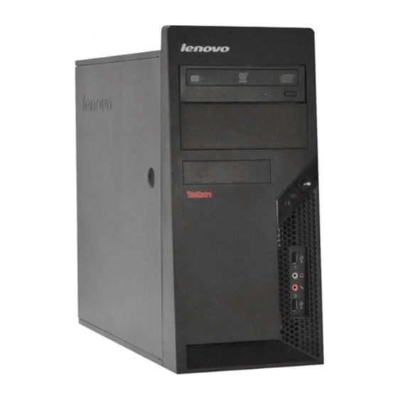
Locating connectors on the front of the computer The following illustration shows the location of connectors on the front of the computer. USB connector Headphone connector Hardware Replacement Guide Microphone connector USB connector... -
Page 11: Locating Connectors On The Rear Of The Computer
Locating connectors on the rear of the computer The following illustration shows the location of connectors on the rear of the computer. Power supply diagnostic LEDs Voltage selection switch (some models) Power connector Standard mouse connector Standard keyboard connector Serial connector Parallel connector VGA monitor connector USB connectors (2) -
Page 12: Identifying Parts On The System Board
Identifying parts on the system board The system board (sometimes called the planar or motherboard) is the main circuit board in your computer. It provides basic computer functions and supports a variety of devices that are factory-installed or that you can install later. The following illustration shows the locations of parts on the system board (some models). - Page 13 The following illustration shows the locations of parts on the system board (some models). Microprocessor and heat sink Microprocessor fan connector Memory connector 1 Memory connector 2 Power connector Diskette drive connector IDE connector SATA IDE connectors (2) Power fan connector Front panel connector Clear CMOS/Recovery jumper Front USB connectors (2)
- Page 14 The following illustration shows the locations of parts on the system board (some models). Microprocessor and heat sink Microprocessor fan connector Memory connector 1 Memory connector 2 Diskette drive connector Power connector IDE connector 1 IDE connector 2 Power fan connector SATA IDE connector (2) Clear CMOS/Recovery jumper Hardware Replacement Guide...
-
Page 15: Chapter 2. Replacing Hardware
“Locating connectors on the rear of the computer” on page 3. 4. Remove any locking devices that secure the computer cover. 5. If there are thumbscrews securing the cover, remove them. © Lenovo 2006, 2007. Portions © IBM Corp. 2005. - Page 16 6. Press the cover-release button on the side of the cover and slide the computer cover to the rear to and remove. Hardware Replacement Guide...
-
Page 17: Removing And Replacing The Front Bezel
Removing and replacing the front bezel To remove and replace the front bezel: 1. Remove the computer cover. See “Removing the computer cover” on page 7. 2. Remove the front bezel by releasing the three plastic tabs on the left side and pivoting the bezel outward. -
Page 18: Replacing The Power Supply
6. Install the four screws to secure the power supply. Note: Use only the screws provided by Lenovo. 7. Reconnect the power supply connectors to the system board. 8. Reconnect a power supply connector to each of the drives. -
Page 19: Replacing The Heat Sink Assembly
Safety and Warranty Guide that was included with your computer. To obtain copies of the Safety and Warranty Guide, go to the Support Web site at http://www.lenovo.com/support. To replace the heat sink assembly: 1. Remove the computer cover. See “Removing the computer cover” on page 7. - Page 20 a. Pivot the handle 1 to release the heat sink clamp and then disengage the clamp from the plastic retention bracket. b. Remove the four screws 1 securing the heat sink and fan assembly to the system board. Note: You might have to gently twist the heat sink to free it from the microprocessor.
- Page 21 7. Use the thermal grease syringe to place five drops of grease on the top of the microprocessor. Each drop of grease should be 0.03ml (3 tick marks on the grease syringe). 8. Depending on which heat sink you are installing, do one of the following: Chapter 2.
- Page 22 a. Position the heat sink on the microprocessor socket and then position the clamp on the plastic retention bracket. Pivot the handle 1 to clamp the heat sink to the plastic retention bracket. b. Position the heat sink on the plastic retention bracket so that the four screws are aligned with the posts on the system board.
-
Page 23: Replacing A Memory Module
Safety and Warranty Guide that was included with your computer. To obtain copies of the Safety and Warranty Guide, go to the Support Web site at http://www.lenovo.com/support. To replace a memory module: 1. Remove the computer cover. See “Removing the computer cover” on page 7. -
Page 24: Replacing An Adapter
Safety and Warranty Guide that was included with your computer. To obtain copies of the Safety and Warranty Guide, go to the Support Web site at http://www.lenovo.com/support. To replace an adapter: 1. Remove the computer cover. See “Removing the computer cover” on page 7. -
Page 25: Replacing The Hard Disk Drive
Do not remove the computer cover or attempt any repair before reading the “Important safety information” in the Safety and Warranty Guide that was included with your computer. To obtain copies of the Safety and Warranty Guide, go to the Support Web site at http://www.lenovo.com/support. Chapter 2. Replacing hardware... - Page 26 Important When you receive a new hard disk drive, you will also receive a set of Product Recovery discs. The Product Recovery discs will enable you to restore the contents of the hard disk to the same state as when your computer was originally shipped from the factory.
- Page 27 7. To install the new hard disk drive into the blue bracket, flex the bracket and align the pins 1 through 4 on the bracket with the holes in the hard disk drive. Do not touch the circuit board 5 on the bottom of the hard disk drive. 8.
- Page 28 9. Align the drive cage pivot pin with the slot 1 in the upper drive cage and slide the hard disk drive cage into the chassis. 10. Press down on the metal latch 2 and pivot in the drive cage into place and then slide it forward until it snaps into position.
-
Page 29: Replacing An Optical Drive
Safety and Warranty Guide that was included with your computer. To obtain copies of the Safety and Warranty Guide, go to the Support Web site at http://www.lenovo.com/support. To replace an optical drive 1. Remove the computer cover. See “Removing the computer cover” on page 7. -
Page 30: Replacing The Diskette Drive
Safety and Warranty Guide that was included with your computer. To obtain copies of the Safety and Warranty Guide, go to the Support Web site at http://www.lenovo.com/support. To replace the diskette drive: 1. Remove the computer cover. See “Removing the computer cover” on page 7. -
Page 31: Replacing The System Fan Assembly
Safety and Warranty Guide that was included with your computer. To obtain copies of the Safety and Warranty Guide, go to the Support Web site at http://www.lenovo.com/support. To replace the system fan assembly: 1. Remove the computer cover. See “Removing the computer cover” on page 7. - Page 32 4. Pull the system fan assembly out of chassis. 5. Install the new system fan assembly by aligning the rubber mounts of the system fan assembly with the holes on the chassis and push the rubber mounts through the holes. 6.
-
Page 33: Replacing The Keyboard
Safety and Warranty Guide that was included with your computer. To obtain copies of the Safety and Warranty Guide, go to the Support Web site at http://www.lenovo.com/support. To replace the keyboard: 1. Remove any media (diskettes, CDs, or tapes) from the drives, shut down your operating system, and turn off all attached devices and the computer. -
Page 34: Completing The Installation
3. Locate the connector for the mouse. See “Locating connectors on the front of the computer” on page 2 and “Locating connectors on the rear of the computer” on page 3. Note: Your mouse might be connected to the standard mouse connector 1 at the rear of the computer or to a USB connector 2 at either the front or rear of the computer. - Page 35 7. To update your configuration settings, see ″Starting the Setup Utility″ in the User Guide. Note: In most areas of the world, Lenovo requires the return of the defective CRU. Information about this will come with the CRU or will come a few days after the CRU arrives.
-
Page 36: Updating (Flashing) Bios From A Diskette Or Cd-Rom
1. Insert a system program update (flash) diskette or CD-ROM into the diskette drive or optical drive. System program updates are available at http://www.lenovo.com/support on the World Wide Web. Note: To insert a CD-ROM into the optical drive, the computer must be turned 2. -
Page 37: Appendix. Notices
Web sites. The materials at those Web sites are not part of the materials for this Lenovo product, and use of those Web sites is at your own risk. -
Page 38: Television Output Notice
Macrovision Corporation. Reverse engineering or disassembly is prohibited. Trademarks The following terms are trademarks of Lenovo in the United States, other countries, or both: Lenovo ThinkCentre Other company, product, or service names may be trademarks or service marks of others. - Page 40 Part Number: 41X5705 Printed in USA (1P) P/N: 41X5705...
Need help?
Do you have a question about the ThinkCentre A55 8705 and is the answer not in the manual?
Questions and answers