Table of Contents
Advertisement
Advertisement
Table of Contents

Related Manuals for Cisco Catalyst IE9300


Summary of Contents for Cisco Catalyst IE9300
- Page 1 Cisco Catalyst IE9300 Rugged Series Switch Hardware Installation Guide First Published: 2022-04-26 Last Modified: 2022-10-03 Americas Headquarters Cisco Systems, Inc. 170 West Tasman Drive San Jose, CA 95134-1706 http://www.cisco.com Tel: 408 526-4000 800 553-NETS (6387) Fax: 408 527-0883...
-
Page 2: Communications, Services, And Additional Information
Cisco and the Cisco logo are trademarks or registered trademarks of Cisco and/or its affiliates in the U.S. and other countries. To view a list of Cisco trademarks, go to this URL: https://www.cisco.com/c/en/us/about/legal/trademarks.html. -
Page 3: Cisco Bug Search Tool
Cisco Bug Search Tool (BST) is a gateway to the Cisco bug-tracking system, which maintains a comprehensive list of defects and vulnerabilities in Cisco products and software. The BST provides you with detailed defect information about your products and software. -
Page 5: Table Of Contents
Alarms Console Ports SD Card Connector USB Host Port Stacking Interface C H A P T E R 2 Switch Installation Preparing for Installation Warnings Installation Guidelines Required Tools and Equipment Cisco Catalyst IE9300 Rugged Series Switch Hardware Installation Guide... - Page 6 Power Supply Modules Power Supply Installation Guidelines Installing a Power-Supply Module Required Tools and Equipment Ground the Switch Install the Power-Supply Module in the Switch Wire the Power Source Remove the Power-Supply Module Cisco Catalyst IE9300 Rugged Series Switch Hardware Installation Guide...
- Page 7 10/100/1000 Port Connections SFP Module Interface Settings Ping End Device Spanning Tree Loops Switch Performance Speed, Duplex, and Autonegotiation Autonegotiation and Network Interface Cards Cabling Distance Reset the Switch Recovering Passwords Cisco Catalyst IE9300 Rugged Series Switch Hardware Installation Guide...
- Page 8 EMC Environmental Conditions for Products Installed in the European Union Hazardous Locations Standards C H A P T E R 9 Technical Specifications Switch Specifications Power-Supply Module Specifications Alarm Ratings Cisco Catalyst IE9300 Rugged Series Switch Hardware Installation Guide viii...
-
Page 9: Cisco Ie9300 Rugged Series Overview
These devices include programmable logic controllers (PLCs), human-machine interfaces (HMIs), drives, sensors, and input and output (I/O) devices. Switch Models The Cisco Catalyst IE9300 Rugged Series Switch is available in two hardware models, each with two different software options. Cisco Catalyst IE9300 Rugged Series Switch Hardware Installation Guide... - Page 10 An -E indicates that the model has a Network Essentials license. For information about differences between the licenses, see the Cisco Catalyst IE9300 Rugged Series Switchdata sheet on Cisco.com. All Cisco Catalyst IE9300 Rugged Series Switch models have 4 GB of DRAM, four alarm inputs, and one alarm output. Other I/O include the following: •...
-
Page 11: Front Panel
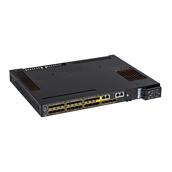
Front Panel Front Panel All the ports and LEDs of Cisco Catalyst IE9300 Rugged Series Switches are on the front panel. This section shows the arrangement of features on the front panel; see other sections for detailed information about ports and LEDs. -
Page 12: Display Mode Button
The front panel of the Cisco Catalyst IE9300 Rugged Series Switch has an Express Setup button and a setup LED. The button is recessed to prevent accidental activation; you need a paper clip or similar object to press it. -
Page 13: System Led
Disconnect a device from a switch port, and then press the Express Setup button. System LED The system LED provides basic status about the health of the Cisco Catalyst IE9300 Rugged Series Switch. Table 4: System LED Color System Status System is not powered on. - Page 14 LEDs turn on when the power is available and remain on regardless of the software state. For details about the power supply and its LED, see the section Power Supply Modules, on page Cisco Catalyst IE9300 Rugged Series Switch Hardware Installation Guide...
-
Page 15: Gigabit Ethernet Ports
Gigabit Ethernet Ports Gigabit Ethernet Ports The Cisco Catalyst IE9300 Rugged Series Switch supports four uplink (1G) ports and 24 downlink ports. Two of the downlink ports can function as dual-media downlink ports, providing an SFP interface and a copper interface. -
Page 16: Alarms
Stack member number. Alarms Each Cisco Catalyst IE9300 Rugged Series Switch has four alarm inputs and one output. You can connect up to four alarm inputs from different devices—such as a door, or temperature gauge—to the alarm port. You can use the CLI to set the alarm severity to minor or major. -
Page 17: Console Ports
Major alarm condition is present. Console Ports The Cisco Catalyst IE9300 Rugged Series Switch has two console ports: one RS-232 port with an RJ-45 connector, and one USB port with a micro-USB connector. The USB port is behind a small door on the front panel. -
Page 18: Sd Card Connector
SD Card Connector The Cisco Catalyst IE9300 Rugged Series Switch has a secure digital (SD) card connector. You can use the connector for the Swap Drive feature and to copy files on and off the system. The slot is behind a door on the front panel. -
Page 19: Usb Host Port
USB Host Port USB Host Port The Cisco Catalyst IE9300 Rugged Series Switch has a USB-A host port on the front panel. Note that the port is intended only for service operation and not for continuous use. Table 11: USB Host Port LEDs... - Page 20 Cisco IE9300 Rugged Series Overview Stacking Interface Cisco Catalyst IE9300 Rugged Series Switch Hardware Installation Guide...
-
Page 21: Switch Installation
Connecting Devices to the Ethernet Ports, on page 35 Preparing for Installation Before you install a Cisco Catalyst IE9300 Rugged Series Switch, you must read, understand, and observe the warnings and guidelines in this section. You also must verify the switch package contents, gather the required tools and equipment, and verify the switch operations. - Page 22 (4.4 cm). Statement 1076 Warning Avoid using or servicing any equipment that has outdoor connections during an electrical storm. There may be a risk of electric shock from lightning. Statement 1088 Cisco Catalyst IE9300 Rugged Series Switch Hardware Installation Guide...
-
Page 23: Installation Guidelines
Installation Guidelines Installation Guidelines Before installing the Cisco Catalyst IE9300 Rugged Series Switch, be sure to meet the following guidelines: • Cabling is away from sources of electrical noise, such as radios, power lines, and fluorescent lighting fixtures. Make sure that the cabling is away from other devices that might damage the cables. -
Page 24: Switch Installation
Source. See the Installing the Switch to install the switch in a rack or on a wall. Switch Installation You can install the Cisco Catalyst IE9300 Rugged Series Switch in a 19-inch, 23-inch, or ETSI rack or on a wall. Follow the instructions in the appropriate section. -
Page 25: Attach Brackets For 19-Inch Racks
Decide whether you will use a front-, mid-, or rear-mounting of the switch in the rack. Step 2 Attach the brackets to the switches, following the steps in the appropriate illustrations. Figure 5: Attaching Brackets: Front Mounting Figure 6: Attaching Brackets: Midmounting Cisco Catalyst IE9300 Rugged Series Switch Hardware Installation Guide... -
Page 26: Attach Brackets For 19-Inch Racks For Ip-30 Compliance (Optional)
Before installing the mounting brackets, install the rubber plugs in the unused mounting holes. The following figure shows a close-up of the rubber plugs and how to install the rubber plugs in the holes. Figure 8: Inserting a Rubber Plug Rubber plug Screwdriver Cisco Catalyst IE9300 Rugged Series Switch Hardware Installation Guide... - Page 27 Insert the rubber plugs in the appropriate holes on both sides of the switch, as shown in the first illustration in this section. Step 5 Use a screwdriver or pen to push in the rubber plugs completely. What to do next Complete the steps in the section Rack-Mount the Switch, on page Cisco Catalyst IE9300 Rugged Series Switch Hardware Installation Guide...
-
Page 28: Attach Brackets For 23-Inch Racks
Complete the tasks in the section Preparing for Installation. Attach the brackets to the switch, as shown in one of the illustrations. Figure 10: Attaching Brackets for 23-inch Racks (Front Mounting) Cisco Catalyst IE9300 Rugged Series Switch Hardware Installation Guide... -
Page 29: Attach Brackets For Etsi Racks
18. Do so before installing the brackets. Before you begin Complete the tasks in the section Preparing for Installation. Attach the brackets to the switch, following the steps in the illustration. Cisco Catalyst IE9300 Rugged Series Switch Hardware Installation Guide... -
Page 30: Rack-Mount The Switch
After you attach the brackets on the switch, attach the brackets to the rack, using the following illustrations and steps. The illustration displays, from top to bottom, midrack mounting, front mounting, and rear mounting. Cisco Catalyst IE9300 Rugged Series Switch Hardware Installation Guide... - Page 31 Rack-Mount the Switch Figure 13: Rack-Mounting the Switch Note The preceding illustration shows rack mounting for a Cisco IE5000 switch, but the mounting is the same as for Cisco Catalyst IE9300 Rugged Series Switches. Before you begin Attach the brackets to the rack, following instructions in one of the following sections: •...
-
Page 32: Installing Multiple Switches In The Rack
Ports. Installing Multiple Switches in the Rack You can mount two Cisco Catalyst IE9300 Rugged Series Switches in 19- or 23- inch racks. To install each switch, follow the instructions for the appropriate rack earlier in this chapter. You can also mount two IE9320 GE Fiber switches in a rack and connect them with a stacking cable. The connection enables you to treat the two switches as if they were one. -
Page 33: Wall-Mount Installation
The temperature derating for the top unit applies to the entire stack. Wall-Mount Installation To wall-mount the switch, follow the steps in these sections: • Attach Wall-Mount Brackets, on page 27 • Wall-Mount the Switch, on page 28 Cisco Catalyst IE9300 Rugged Series Switch Hardware Installation Guide... - Page 34 The position of the cable entrance does not affect the temperature of the switch. Switch Wall Gap Temperature Derating IE9310 GE Fiber 0.75 in No derating Cisco Catalyst IE9300 Rugged Series Switch Hardware Installation Guide...
-
Page 35: Attach Wall-Mount Brackets
• Base side (facing wall): 0 in (0 cm) Attach Wall-Mount Brackets Attach the brackets to the switch so that you can attach it to a wall. Attach the switch to the wall, as shown in the following illustration: Cisco Catalyst IE9300 Rugged Series Switch Hardware Installation Guide... -
Page 36: Wall-Mount The Switch
For the best support of the switch and cables, ensure that the switch is attached securely to wall studs or to a firmly attached mounting backboard. Orientation should exactly match the following figure, with the venting and Cisco logo facing away from the wall. -
Page 37: Sfp Installation
Source. • Connect the switch ports. See the section Connecting Devices to the Ethernet Ports. SFP Installation This section presents procedures to install and remove fiber-optic and 1000BASE-T SFP transceiver modules. Cisco Catalyst IE9300 Rugged Series Switch Hardware Installation Guide... -
Page 38: Sfp Installation Considerations And Guidelines
Depending on the SFP module you use, the operating temperature limits may be affected. Choose an SFP module appropriate to the installed environment. For a complete list of supported SFP modules, see the Cisco Catalyst IE9300 Rugged Series Data Sheet on Cisco.com. Cisco Catalyst IE9300 Rugged Series Switch Hardware Installation Guide... -
Page 39: Install Fiber Optic Sfp Modules
When connecting to a 100/1000BASE-T-compatible server, workstation, or router, use four twisted-pair, straight-through CAT5 or later cabling for the SFP transceiver port. When connecting to a 100/1000BASE-T-compatible switch or repeater, use four twisted-pair, crossover CAT5 cabling. Cisco Catalyst IE9300 Rugged Series Switch Hardware Installation Guide... - Page 40 Position the SFP transceiver in front of the port socket opening. Note Different Cisco devices have different SFP transceiver socket configurations. Your Cisco device might require that the SFP transceiver be installed with the bale-clasp either in a latch-up or a latch-down orientation. Verify that you have the SFP transceiver oriented correctly when you position it in front of the port socket.
-
Page 41: Guidance For Connecting To Sfp Modules
Insert the other cable end into a fiber-optic receptacle on a target device. Step 4 Observe the port status LED: • The LED turns green when the switch and the target device have an established link. Cisco Catalyst IE9300 Rugged Series Switch Hardware Installation Guide... -
Page 42: Connect To A 1000Base-T Sfp Module
Remove SFP Modules Remove an SFP module. Step 1 Attach an ESD-preventive wrist strap to your wrist and to a bare metal surface. Step 2 Disconnect the cable from the SFP module. Cisco Catalyst IE9300 Rugged Series Switch Hardware Installation Guide... -
Page 43: Replace The Sd Flash Memory Card
To maximize performance, either let the ports autonegotiate both speed and duplex, or set the port speed and duplex parameters on both ends of the connection. Cisco Catalyst IE9300 Rugged Series Switch Hardware Installation Guide... - Page 44 Switch Installation Connecting Devices to the Ethernet Ports See the switch software configuration guide or the switch command reference on Cisco.com for more information about autonegotiation and auto-MDIX. For simplified cabling, the automatic medium-dependent interface crossover (auto-MDIX) feature is enabled by default.
-
Page 45: Power Supply Installation
Table 14: Power Supply Modules Model Description PWR-RGD-LOW-DC-H Low voltage DC. For detailed specifications, see the Cisco Catalyst IE9300 Rugged Series Switch data sheet. PWR-RGD-AC-DC-H AC and high-voltage DC. For detailed specifications, see the Cisco Catalyst IE9300 Rugged Series Switch data sheet. -
Page 46: Power Supply Installation Guidelines
Power Supply Installation Guidelines Observe the guidelines in this section when removing or installing a power-supply module. A power-supply module that is only partially connected to the switch disrupts the system operation. Cisco Catalyst IE9300 Rugged Series Switch Hardware Installation Guide... -
Page 47: Installing A Power-Supply Module
Equipment installation must comply with local and national electrical codes. Required Tools and Equipment Obtain the following tools and equipment: • Torque driver(s) capable of 5 to 35 in-lbs • Ring, spade, or flanged spade terminal (terminals should be insulated) Cisco Catalyst IE9300 Rugged Series Switch Hardware Installation Guide... -
Page 48: Ground The Switch
This equipment must be grounded. Never defeat the ground conductor or operate the equipment in the absence of a suitably installed ground conductor. Contact the appropriate electrical inspection authority or an electrician if you are uncertain that suitable grounding is available. Statement 1024 Cisco Catalyst IE9300 Rugged Series Switch Hardware Installation Guide... - Page 49 Slide the ground screw from Step 1 through the terminal lug and insert the ground screws into the opening on the cable side, as shown in the following illustration. Figure 22: Attaching the Terminal Lug Cisco Catalyst IE9300 Rugged Series Switch Hardware Installation Guide...
-
Page 50: Install The Power-Supply Module In The Switch
Use a Phillips screwdriver to loosen the two captive screws of the blank power-supply module and gently pull it out, as shown in the following illustrations. Figure 23: Loosening the Screws on the Power-Supply Blank Cisco Catalyst IE9300 Rugged Series Switch Hardware Installation Guide... -
Page 51: Wire The Power Source
A readily accessible two-poled disconnect device must be incorporated in the fixed wiring. Statement 1022 Warning Only trained and qualified personnel should be allowed to install or replace this equipment. Statement 1030 Cisco Catalyst IE9300 Rugged Series Switch Hardware Installation Guide... - Page 52 PSU1 (power-supply module 1) PSU2 (power-supply module 2) Positive connection for low-voltage DC Positive connection for low-voltage DC (PSU1) (PSU2) Negative connection for low-voltage DC Negative connection for low-voltage DC (PSU1) (PSU2) Cisco Catalyst IE9300 Rugged Series Switch Hardware Installation Guide...
- Page 53 • Low-voltage DC Power-Supply Module: Connect the wires to the terminals labeled "Lo." • High-voltage DC Power-Supply Module: Connect the wires to the terminals labeled "Hi," as shown in the following illustration. Cisco Catalyst IE9300 Rugged Series Switch Hardware Installation Guide...
-
Page 54: Remove The Power-Supply Module
Locate the circuit breakers, turn them OFF, and lock out the circuit. Warning If the power is not off at the AC or DC circuit breaker, do not touch the power-input terminal. Cisco Catalyst IE9300 Rugged Series Switch Hardware Installation Guide... - Page 55 To prevent exposure to hazardous voltages and to contain electromagnetic interference (EMI), either a Caution power-supply module or a blank cover must be in each power-supply module slot at all times. Figure 32: Removing the Power-Supply Module Cisco Catalyst IE9300 Rugged Series Switch Hardware Installation Guide...
- Page 56 Power Supply Installation Remove the Power-Supply Module Cisco Catalyst IE9300 Rugged Series Switch Hardware Installation Guide...
-
Page 57: Express Setup
• A small paper clip to reach the button. Note Before running Express Setup, disable any pop-up blockers or proxy settings on your browser and any wireless client running on your computer. Cisco Catalyst IE9300 Rugged Series Switch Hardware Installation Guide... -
Page 58: Run Express Setup
When released, the LED of one of the dual-media downlink ports starts flashing green, depending on whether downlink ports are connected. If no dual-media downlink ports are connected, the lowest port flashes (Gi1/0/1). If both dual-media downlink ports are connected, the lowest port flashes (Gi1/0/23). Cisco Catalyst IE9300 Rugged Series Switch Hardware Installation Guide... - Page 59 • Default Gateway: Enter the IP address of the router (not optional if IP is static). You must enter the router IP address if the IP address is static. (Optional) On this screen you can also enable or disable Telnet and SSH and configure CIP settings. Cisco Catalyst IE9300 Rugged Series Switch Hardware Installation Guide...
- Page 60 If you changed the static IP address on your computer, change it to the previously configured static IP address. What to do next You can display Web UI by following these steps: Cisco Catalyst IE9300 Rugged Series Switch Hardware Installation Guide...
- Page 61 • When the LED on the switch port that is connected to the computer is green, reenter the switch IP address in a web browser to display the Web UI. When Web UI appears, you can continue with the switch configuration. Cisco Catalyst IE9300 Rugged Series Switch Hardware Installation Guide...
- Page 62 Express Setup Run Express Setup Cisco Catalyst IE9300 Rugged Series Switch Hardware Installation Guide...
-
Page 63: Switch Configuration With The Cli Setup Program
Switch Installation chapter. Accessing the CLI Through the Console Port You can enter Cisco IOS commands and parameters through the CLI. Use one of these options to access the CLI: RJ-45 Console Port Complete the steps in this section to access the CLI through the RJ-45 console port. -
Page 64: Usb Micro-Type B Console Port
Choose Start > Control Panel > Systems. b) Click the Hardware tab and then choose Device Manager. c) Expand Ports. The assigned COM port appears in parenthesis at the end of the line with this entry: Cisco USB System Management Console. Step 3 Start the terminal-emulation program on the PC or the terminal. -
Page 65: Entering The Initial Configuration Information
Complete the following steps to complete the setup program and to create an initial configuration for the switch: Step 1 Enter Yes at these two prompts as shown in the following example: Cisco Catalyst IE9300 Rugged Series Switch Hardware Installation Guide... - Page 66 Step 6 (Optional) Configure Simple Network Management Protocol (SNMP) by responding to the prompts. You can also configure SNMP later through the CLI, Cisco Device Manager, or the Cisco Network Assistant application. To configure SNMP later, enter no. Configure SNMP Network Management? [no]: no...
- Page 67 % Error: The application: day0guestshell, does not exist GigabitEthernet1/0/18 Configuring interface GigabitEthernet1/0/18: The following configuration command script was created: hostname Clarke_DUAL enable secret 9 $9$AZAmDMsIKNr/D.$OL1hR8VYAamo3DBeaV1O9WVVw9Wust.HJM3Z3oOlWBw enable password Iotg@123 line vty 0 15 password Iotg@12345 Cisco Catalyst IE9300 Rugged Series Switch Hardware Installation Guide...
- Page 68 GigabitEthernet1/0/15 interface GigabitEthernet1/0/16 interface GigabitEthernet1/0/17 interface GigabitEthernet1/0/18 no switchport no shutdown no ip address interface GigabitEthernet1/0/19 interface GigabitEthernet1/0/20 interface GigabitEthernet1/0/21 interface GigabitEthernet1/0/22 interface GigabitEthernet1/0/23 interface GigabitEthernet1/0/24 interface GigabitEthernet1/0/25 interface GigabitEthernet1/0/26 Cisco Catalyst IE9300 Rugged Series Switch Hardware Installation Guide...
- Page 69 To use the CLI, enter commands at the Switch > prompt through the console port by using a terminal emulation program or through the network by using Telnet. For configuration information, see the switch software configuration guides on Cisco.com. Cisco Catalyst IE9300 Rugged Series Switch Hardware Installation Guide...
- Page 70 Switch Configuration with the CLI Setup Program Complete the Setup Program Cisco Catalyst IE9300 Rugged Series Switch Hardware Installation Guide...
-
Page 71: Troubleshooting
Switch Boot Fast Contact your Cisco TAC representative if your switch does not successfully boot. Note You can disable boot fast and run POST by using the Cisco IOS CLI. See the appropriate configuration guide for more information. Switch LEDs Look at the port LEDs information when troubleshooting the switch. -
Page 72: Switch Connections
• Verify that you are using the correct cable type. See Cables and Connectors for information. • Look for loose connections. Sometimes a cable appears to be seated but is not. Disconnect the cable, and then reconnect it. Cisco Catalyst IE9300 Rugged Series Switch Hardware Installation Guide... -
Page 73: 10/100/1000 Port Connections
This encoding verifies that the module meets the requirements for the switch. • Inspect the SFP module. Exchange the suspect module with a known good module. • Verify that the module is supported on this platform. (The switch release notes on Cisco.com list the SFP modules that the switch supports.) •... -
Page 74: Switch Performance
These are reasons why you might want to reset the switch to the factory default settings: • You installed the switch in your network and cannot connect to it because you assigned the wrong IP address. • You want to reset the password on the switch. Cisco Catalyst IE9300 Rugged Series Switch Hardware Installation Guide... -
Page 75: Recovering Passwords
Finding the Switch Serial Number If you contact Cisco Technical Assistance, you need to know the serial number of your switch. The serial number is on the top of the switch. You can also use the show version command to obtain the switch serial number. - Page 76 Troubleshooting Finding the Switch Serial Number Cisco Catalyst IE9300 Rugged Series Switch Hardware Installation Guide...
-
Page 77: Cables And Connectors
Connector pins 1, 2, 3, and 6 are used for PoE. SFP Module Connectors The illustration below shows an LC style connector that is used with the SFP Module slots. It is a fiber-optic cable connector. Cisco Catalyst IE9300 Rugged Series Switch Hardware Installation Guide... -
Page 78: Console Port
The USB micro Type A-to-USB mini-Type B cable is not supplied. Note When running Linux, access the USB Console using Minicom instead of Screen. Figure 37: USB Micro Type B-to-USB 5-Pin Micro-Type B Cable Cisco Catalyst IE9300 Rugged Series Switch Hardware Installation Guide... -
Page 79: Alarm Port
Each port must match the wave-length specifications on each end of the cable, and for reliable communications, the cable must not exceed the allowable length For more information about SFP/SFP+ modules and cables, see Transceiver Modules on Cisco.com. Cisco Catalyst IE9300 Rugged Series Switch Hardware Installation Guide... -
Page 80: Console Port Adapter Pinouts
The RJ-45-to-DB-25 female DTE adapter is not supplied with the switch. You can order this adapter from Cisco (part number ACS-DSBUASYN=). The following table lists the pinouts. Table 17: Console Port Adapter Pinouts (RJ-45-to-DB-25) Switch Console Port (DTE) RJ-45-to-DB-25 Adapter Console Device Signal DB-25 Pin Signal Cisco Catalyst IE9300 Rugged Series Switch Hardware Installation Guide... -
Page 81: Hazardous Location Installation Information
Hazardous Location Installation Information This appendix provides hazardous location installation information for the Cisco Catalyst IE9300 Rugged Series switch. Also refer to the Cisco Catalyst IE 9300 Rugged Series Switch Regulatory and Compliance Document. • Hazardous Area Installation Warnings, on page 73 •... - Page 82 Before performing any of the following procedures, locate the DC circuit to ensure that the power is removed and cannot be turned on accidentally, or verify that the area is nonhazardous before proceeding. Statement 1059 Cisco Catalyst IE9300 Rugged Series Switch Hardware Installation Guide...
-
Page 83: North American Hazardous Location Approval
être utilisé pour déterminer le code de température global du système. Les combinaisons d'équipements dans le système sont sujettes à inspection par les autorités locales qualifiées au moment de l'installation. Cisco Catalyst IE9300 Rugged Series Switch Hardware Installation Guide... -
Page 84: Emc Environmental Conditions For Products Installed In The European Union
UL 60079-15, 5e éd., 2020-04-07 CAN/CSA-C22.2 No 60079-15:18, November 2018 CAN/CSA-C22.2 No 60079-15:18, novembre 2018 EN IEC 60079-15: 2019 EN IEC 60079-15: 2019 The following table lists the hazardous location strings in English and French. Cisco Catalyst IE9300 Rugged Series Switch Hardware Installation Guide... - Page 85 II 3 G, Ex ec nC IIC T4 Gc UL 21 ATEX 2657X UL 21 ATEX 2657X Class 1, Zone 2, AEx ec nC IIC T4 Gc X Classe 1, Zone 2, AEx ec nC IIC T4 Gc X Cisco Catalyst IE9300 Rugged Series Switch Hardware Installation Guide...
- Page 86 Hazardous Location Installation Information Hazardous Locations Standards Cisco Catalyst IE9300 Rugged Series Switch Hardware Installation Guide...
-
Page 87: Technical Specifications
Operating temperature • –40° C to +75°C (blower equipped cabinet) • –40° C to +70° C (vented cabinet) • –40° C to +60° C (sealed cabinet) Storage temperature –40°C to +85°C Cisco Catalyst IE9300 Rugged Series Switch Hardware Installation Guide... - Page 88 90 to 264 VAC, 50 to 60 Hz 90 to 300 VDC • PWR-RGD-AC-DC-250: 90 to 264 VAC, 50 to 60 Hz 90 to 300 VDC • PWR-RGD-LOW-DC-H: 18 to 75 VDC Cisco Catalyst IE9300 Rugged Series Switch Hardware Installation Guide...
-
Page 89: Power-Supply Module Specifications
Alarm output electrical specification 30VDC @ 1A, 60VDC @ 0.5A Caution To reduce risk of electric shock and fire, the alarm ports must be connected to an IEC 60950/IEC 62368-compliant limited power source (LPS). Cisco Catalyst IE9300 Rugged Series Switch Hardware Installation Guide... - Page 90 Technical Specifications Alarm Ratings Cisco Catalyst IE9300 Rugged Series Switch Hardware Installation Guide...
Need help?
Do you have a question about the Catalyst IE9300 and is the answer not in the manual?
Questions and answers