
Related Manuals for Panasonic KX-T7730X


Summary of Contents for Panasonic KX-T7730X
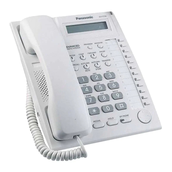
- Page 1 ORDER NO. KMS0110592C3 PROPRIETARY TELEPHONE KX-T7730X (for Asia, Middle Near East, Africa and Latin America) SPECIFICATIONS 1. INTRODUCTION 1.1. NOTE When you note the serial number, write down all of the 11 digits.
-
Page 2: For Service Technicians
The serial number may be found on the label affixed to the bottom of the unit. 1.2. FOR SERVICE TECHNICIANS ICs and LSIs are vulnerable to static electricity. When repairing, the following precautions will help prevent recurring malfunctions. 1. Cover the plastic parts boxes with aluminum foil. 2. - Page 4 3. CONNECTION Caution: Ensure the cord is inserted in the groove to prevent damage to the connector. 4. DISASSEMBLY INSTRUCTIONS...
- Page 5 1. Remove the Stand. 2. Remove 4 Screws (A). 3. Remove the Bottom Cabinet. 4. Remove the Connector (1~3) and the Flat Cable from the Main Board.
- Page 6 5. Remove 2 Screws (A). 6. Remove the Main Board from the Top Cabinet. 7. Remove the Cable from the Main Board. 8. Remove the LCD Holder by sliding the Hook in the direction of the arrow from the Main Board. 5.
- Page 7 Pin No. Terminal I/O Function I/O Setting Description Name LCD linage H:3line Model L:Other TEST Vcc Connection OSC1 4MHz OSC2 4MHz RESET Not used Vcc Connection Open HS SM mute HF MM mute O( I ) HF SM mute(This is also model code.) HF Relay HS power on HF power on (CS)
-
Page 8: Key Input Control Circuit
LED1 Pin No. Terminal I/O Function I/O Setting Description Name LED2 LED3 LED4 LED5 LED6 LED7 HF SP vol 1 HF SP vol 2 HF SP vol 3 HF SP vol 4 Tone cont 1 Tone cont 2 Tone cont 3 Tone cont 4 HS SP vol 1 HS SP vol 2... -
Page 9: Led Circuit
7.2. LED CIRCUIT Circuit Operation: The LED executes dynamic lighting for the status indicators, and control is executed by the output ports R20~R23, R60~R63, R70~R73. -
Page 10: Data Communication Circuit
7.3. DATA COMMUNICATION CIRCUIT Function: The data communication circuit serves the following functions: Information exchanger between the PBX and proprietary telephone, key input information as well as data for the LED control, LCD control, etc. This information is continuously exchanged at all times. -
Page 11: Tone Generation Circuit
7.4. TONE GENERATION CIRCUIT Function: This circuit generates all system tones including COL, extension, busy, DTMF signals and key in confirmation tones during the power failure mode and is comprised of IC1(DTMF Generator) and IC5 (Analog Switch). Circuit Operation: For an output of a single row tone, the row terminal and the each column terminals intersecting with it are required to be brought a low state. -
Page 12: Handset Circuit
CONDITION IC1 pin52 IC5 SWA IC1 pin53 IC5 SWB IC1 pin54 IC5 SWC IC1 pin55 IC5 SWD Ringing Call Waiting Tone Dial (Handset) Tone Dial (Speakerphone) 7.5. HANDSET CIRCUIT 1) Transmission Signal Path The input signal for the handset microphone is sent through the telephone line via the following path: Handset MIC(JK2) -
Page 13: Speakerphone Circuit
Telephone Line 2) Reception Signal Path The input signal from the telephone line is sent to the receiver through the following path: Telephone Line IC10 R208 Handset Speaker 7.6. SPEAKERPHONE CIRCUIT Function: This circuit controls the automatic switching of the transmitted and received signals to and from the telephone line, when the unit is used in the hands-free mode. - Page 14 Rx (receive) signal is louder, and then it processes the signals so that the louder signal is given precedence. The Voice Detector provides a DC input to the Attenuator Control corresponding to the Tx signal. The Comparator receives a Tx and Rx signal, and supplies DC input to the Attenuator Control corresponding to the Rx signal.
-
Page 15: Troubleshooting Guide
8. TROUBLESHOOTING GUIDE 8.1. NO OPERATION... -
Page 16: Handset Trouble
8.2. HANDSET TROUBLE... -
Page 17: Speaker-Phone Trouble
8.3. SPEAKER-PHONE TROUBLE... -
Page 18: Tone Dial Toruble
8.4. TONE DIAL TORUBLE 8.5. THE ELECTRONIC VOLUME OF THE SPEAKER-PHONE DOES NOT WORK... -
Page 19: The Electronic Volume Of Handset Does Not Work
8.6. THE ELECTRONIC VOLUME OF HANDSET DOES NOT WORK 9. TERMINAL GUIDE OF ICS, TRANSISTORS AND DIODES... -
Page 20: How To Replace The Flat Package Ic
10. HOW TO REPLACE THE FLAT PACKAGE IC If you do not have the special tools (for example: SPOT HEATER) to remove the SPOT HEATER’S Flat IC, If you have solder (large amount) a soldering iron and a cutter knife, you can easily remove IC’s even though large than 100 pin. -
Page 21: Flat Package Ic Installation Procedure
If you do not fill with solder and directly cut the IC lead with the cutter, stress may build up directly in the P.C.board’s pattern. If you do not fill with large quantities of solder as in step 1 the P.C.board pattern may be removed. -
Page 22: Bridge Modification Procedure
pins. *Check the accuracy of the IC setting with the corresponding soldering foil. 2. Apply flux for all pins of FLAT PACKAGE IC. 3. Solder using the specified solder, in the direction of the arrow, by sliding the soldering iron. 10.4. -
Page 23: Accessories And Packing Materials
12. ACCESSORIES AND PACKING MATERIALS... -
Page 24: Replacement Parts List
13. REPLACEMENT PARTS LIST Note:... -
Page 25: Cabinet And Electrical Parts
1. RTL (Retention Time Limited) The marking (RTL) indicates that the Retention Time is limited for this item. After the discontinuation of this assembly in production, the item will continue to be available for a specific period of time. The retention period of availability depends on the type of assembly and the laws governing parts and product retention. -
Page 26: Main Board Parts
Ref. No. Part No. Part Name & Description Remarks PSKM1096Z1 TOP CABINET ABS-94HB PQKE10070Z3 HOOK KBOB ABS-94HB PSGD1065Z CARD,TEL (LARGE) PSHR1264Z COVER,TEL CARD (LARGE) PQHP532X CARD,TEL (SMALL) PQHR576Z COVER,TEL CARD (SMALL) PSGP1088Z PANEL,LED LENZ ABS-94HB PQAS57P03Z SPEAKER PSUS1018Z SPRING PSBH1007Z1 BUTTON, HOOK PC+ABS-94HB PSHG1122Z... - Page 27 Ref. No. Part No. Part Name & Description Remarks PCB1 PSWPT7730X MAIN BOARD ASS'Y (RTL) (ICS) C2ABEE000011 PQVITC7H00F PQVISC77655V PSVICD4066BS PQVINJM2904F PQVIBA06FPE2 C0EBJ0000109 IC10 AN6183SAE1 (TRANSISTORS) B1ADGP000001 TRANSISTOR(SI) B1ADGP000001 TRANSISTOR(SI) 2SC4081R TRANSISTOR(SI) 2SC4081R TRANSISTOR(SI) 2SC4081R TRANSISTOR(SI) B1ABGB000020 TRANSISTOR(SI) PQVTDTA143XU TRANSISTOR(SI) 2SC4081R TRANSISTOR(SI) B1ABGB000020...
- Page 28 Ref. No. Part No. Part Name & Description Remarks PSVD1SRCT PSVD1SRCT PSVD1SRCT PQVDBRPY1204 LED PQVDBRPY1204 LED PQVDBRPY1204 LED PQVDBRPY1204 LED PQVDBRPY1204 LED PQVDBRPY1204 LED PQVDBRPY1204 LED PQVDBRPY1204 LED PQVDBRPY1204 LED PQVDBRPY1204 LED PQVDBRPY1204 LED PQVDBRPY1204 LED MA111 DIODE(SI) MA111 DIODE(SI) MA111 DIODE(SI) MA111...
- Page 29 Ref. No. Part No. Part Name & Description Remarks ECUV1C104KBV 0.1 PQCUV1A475ZF 4.7 ECUV1C104KBV 0.1 ECUV1C104KBV 0.1 ECUV1H332KBV 0.0033 ECUV1H222KBV 0.0022 ECEV0JA221WP 220 ECUV1A106ZF ECUV1C104KBV 0.1 ECUV1H153KBV 0.015 ECUV1C104KBV 0.1 PQCUV1H105JC 1 ECUV1C104ZFV 0.1 ECUV1C104KBV 0.1 ECUV1C104KBV 0.1 ECUV1C473KBV 0.047 ECUV1C473KBV 0.047 ECUV1C473KBV 0.047 ECUV1H333KBV 0.033...
- Page 30 Ref. No. Part No. Part Name & Description Remarks C101 ECUV1H103KBV 0.01 C102 ECUV1H151JCV 150p C103 PQCUV1A225ZF 2.2 C105 ECUV1H103KBV 0.01 C106 ECUV1H103KBV 0.01 C107 ECUV1C104ZFV 0.1 C108 ECUV1H120JCV 12p C109 ECUV1H120JCV 12p C110 ECUV1C104ZFV 0.1 C201 PSCEV1HA100 C203 PSCEV1EA470S 47 C204 ECUV1C104ZFV 0.1 C205...
- Page 31 Ref. No. Part No. Part Name & Description Remarks ERJ3GEYJ273 ERJ3GEYJ103 ERJ3GEYJ473 ERJ3GEYJ473 ERJ3GEYJ472 4.7k ERJ3GEYJ183 ERJ3GEYJ474 470k ERJ3GEYJ472 4.7k ERJ3GEYJ332 3.3k ERJ3GEYJ562 5.6k ERJ3GEYJ562 5.6k ERJ3GEYJ225 2.2M ERJ3GEYJ303 ERJ3GEYJ683 ERJ3GEYJ275 2.7M ERJ3GEYJ104 100k ERJ3GEYJ473 ERJ3GEYJ183 ERJ3GEYJ154 150k ERJ8GEYJ3R3 ERJ3GEYJ222 2.2k ERJ3GEYJ104 100k...
- Page 32 Ref. No. Part No. Part Name & Description Remarks ERJ3GEYJ183 ERJ3GEYJ103 ERJ3GEYJ472 4.7k ERJ3GEYJ474 470k ERJ3GEYJ104 100k ERJ3GEYJ103 ERJ3GEYJ153 ERJ3GEYJ103 R100 ERJ3GEYJ104 100k R101 ERJ3GEYJ221 R102 ERJ3GEYJ221 R103 ERJ3GEYJ103 R104 ERJ3GEYJ103 R105 ERJ3GEYJ101 R106 ERJ3GEYJ222 2.2k R107 ERJ3GEYJ472 4.7k R108 ERJ3GEYJ102 R121 ERJ3GEYJ105...
-
Page 33: For The Schematic Diagram
Ref. No. Part No. Part Name & Description Remarks PSLT9Z4A TRANSFORMER (CRYSTAL OSCILLATOR) H0J400400011 CRYSTAL OSCILLATOR 14. FOR THE SCHEMATIC DIAGRAM Note: 1. DC voltage measurements are taken with an oscilloscope or a tester with a ground. 2. The schematic diagrams and circuit board may be modified at any time with the development of new technology. - Page 34 BRIDGE CIRCUIT (D1) (Q3) Handset Amp HEADSET (Q5,Q8) HANDSET DTMF RINGER DIODE POWER BRIDGE REGULATOR (D2) (IC7) LCD Module SIGNAL TRANSMITTING CIRCUIT(Q101) (IC2) SIGNAL RECEIVING CIRCUIT(Q102) (IC1) DRIVING CIRCUIT RESET IC (Q103,Q104) (IC9) USD PRIVING CIRCUIT (Q105~108) KX-T7730X MAIN BOARD...
- Page 35 FWD/DND MUTE STORE HS_MUTE SW52 SP_RX_MUTE L[7] R138 HOOK K[7] SP_TX_MUTE SP-PHONE R139 HS_POWER R140 SP_POWER R141 The handset is in use 5.4V : Q103 Q103 The speakerphone is in use 0V : Q104 Q104 4.7K KX-T7730X MAIN BOARD NO.1...
- Page 36 5.4V SCK/E 11 D2 C105 5.2V Z0.01 12 D3 13 D4 R128 5.4V C110 14 D5 Z0.1 5.4V 15 D9 SW42 16 D10 R127 R126 R125 HOLD 2.2K 2.2K Q109 R152 Z0.01 5.1V 5.4V 5.4V 5.4V KX-T7730X MAIN BOARD NO.2...
- Page 37 R10 R16 R151 R137 R141 R140 Q109 R139 R138 IC10 R124 R208 R123 C106 C108 R153 R122 C102 C103 C201 R107 Q102 R205 Q201 R204 R202 Q202 R207 R42 R43 C66 C67 30 G2 PSUP1382Z-A KX-T7730X MAIN BOARD COMPONENT VIEW PSUP1382Z...
- Page 38 MESSAGE SW11 CO11 SW12 PAUSE INTERCOM CONF FWD/DND CO10 SW13 AUTO ANS AUTO DIAL TRANSFER SW14 FLASH MUTE SW17 STORE SW18 SW19 SW46 SW20 SW23 SW24 SW25 SW26 SW50 SW43 SW48 REDIAL HOLD SP-PHONE KX-T7730X MAIN BOARD BOTTOM VIEW PSUP1382Z...
Need help?
Do you have a question about the KX-T7730X and is the answer not in the manual?
Questions and answers