Mitsubishi Electric SUZ-SWM40VA Technical & Service Manual
Hide thumbs
Also See for SUZ-SWM40VA:
- Installation manual (296 pages) ,
- Installation manual (20 pages)
Advertisement
Table of Contents
- 1 Table of Contents
- 2 Combination of Indoor and Outdoor Units
- 3 Safety Precaution
- 4 Parts Names and Functions
- 5 Specification
- 6 Noise Criteria Curves
- 7 Outlines and Dimensions
- 8 Wiring Diagram
- 9 Refrigerant System Diagram
- 10 Actuator Control
- 11 Troubleshooting
- 12 Disassembly Procedure
- Download this manual
AIR TO WATER HEAT PUMP UNITS
TECHNICAL & SERVICE MANUAL
R32
[Model Name]
SUZ-SWM40VA
SUZ-SWM60VA
SUZ-SWM80VA
SUZ-SWM40VA.TH
SUZ-SWM60VA.TH
SUZ-SWM80VA.TH
[Service Ref.]
SUZ-SWM40VA.TH
SUZ-SWM60VA.TH
SUZ-SWM80VA.TH
CONTENTS
2. SAFETY PRECAUTION .................................... 2
3. PARTS NAMES AND FUNCTIONS .................. 9
4. SPECIFICATION .............................................. 10
5. NOISE CRITERIA CURVES ............................ 12
6. OUTLINES AND DIMENSIONS ...................... 13
7. WIRING DIAGRAM .......................................... 14
8. REFRIGERANT SYSTEM DIAGRAM ............. 15
9. ACTUATOR CONTROL ................................... 18
10. TROUBLESHOOTING ..................................... 19
11. DISASSEMBLY PROCEDURE ........................ 29
PARTS CATALOG (OCB718)
HFC
utilized
R32
December 2020
No. OCH718
REVISED EDITION-A
Revision:
•Connectable indoor units
have been added in
REVISED EDITION-A.
OCH718 is void.
Note:
•This service manual
describes service data of
the outdoor units only.
Advertisement
Table of Contents

Related Manuals for Mitsubishi Electric SUZ-SWM40VA


Summary of Contents for Mitsubishi Electric SUZ-SWM40VA
-
Page 1: Table Of Contents
AIR TO WATER HEAT PUMP UNITS December 2020 No. OCH718 REVISED EDITION-A TECHNICAL & SERVICE MANUAL Revision: [Model Name] [Service Ref.] •Connectable indoor units SUZ-SWM40VA.TH SUZ-SWM40VA have been added in REVISED EDITION-A. SUZ-SWM60VA.TH SUZ-SWM60VA OCH718 is void. SUZ-SWM80VA.TH SUZ-SWM80VA Note: •This service manual... -
Page 2: Combination Of Indoor And Outdoor Units
COMBINATION OF INDOOR AND OUTDOOR UNITS INDOOR UNIT SERVICE MANUAL Outdoor unit Indoor unit Heat pump type SUZ- Service Service Ref. SWM40VA.TH SWM60VA.TH SWM80VA.TH manual No. EHST17D-VM2DR1.UK EHST17D-YM9DR1.UK ERST17D-VM2DR1.UK ERST17D-VM6DR1.UK EHST20D-MEDR1.UK EHST20D-VM2DR1.UK EHST20D-VM6DR1.UK EHST20D-YM9DR1.UK EHST20D-YM9EDR1.UK EHST20D-TM9DR1.UK OCH714 OCB714 ERST20D-VM2DR1.UK ERST20D-VM6DR1.UK ERST20D-YM9DR1.UK EHST30D-MEDR1.UK EHST30D-VM6EDR1.UK... - Page 3 2-2. CAUTIONS RELATED TO NEW REFRIGERANT Cautions for units utilizing refrigerant R32 Preparation before the repair service Precautions during the repair service • Prepare the proper tools. • Do not perform the work involving the electric parts with wet hands. •...
- Page 4 [1] Warning for service (1) Do not alter the unit. (2) For installation and relocation work, follow the instructions in the Installation Manual and use tools and pipe components specifically made for use with refrigerant specified in the outdoor unit installation manual. (3) Ask a dealer or an authorized technician to install, relocate and repair the unit.
- Page 5 [2] Cautions for unit using R32 refrigerant Basic work procedures are the same as those for conventional units using refrigerant R410A. However, pay careful attention to the following points. (1) Information on servicing (1-1) Checks on the Area Prior to beginning work on systems containing flammable refrigerants, safety checks are necessary to ensure that the risk of ignition is minimized.
- Page 6 (3) Repair to intrinsically Safe Components Do not apply any permanent inductive or capacitance loads to the circuit without ensuring that this will not exceed the permissible voltage and current permitted for the equipment in use. Intrinsically safe components are the only types that can be worked on while live in the presence of a flammable atmos- phere.
- Page 7 b) Isolate system electrically. c) Before attempting the procedure, ensure that: • mechanical handling equipment is available, if required, for handling refrigerant cylinders; • all personal protective equipment is available and being used correctly; • the recovery process is supervised at all times by a competent person; •...
- Page 8 2-4. Minimum installation area If you unavoidably install a unit in a space where all four sides are blocked or there are depressions, confirm that one of these situations (A, B or C) is satisfied. Note: These countermeasures are for keeping safety not for specification guarantee. A) Secure sufficient installation space (minimum installation area Amin).
-
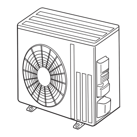
Page 9: Parts Names And Functions
PARTS NAMES AND FUNCTIONS SUZ-SWM40VA.TH SUZ-SWM60VA.TH SUZ-SWM80VA.TH Air inlet (back and side) Piping Drain hose Air outlet Drain outlet Model SUZ-SWM·VA Drain socket Note: Do not use the drain socket in the cold region. Drain may freeze and it makes the fan stop. -
Page 10: Specification
SPECIFICATION Service ref. SUZ-SWM40VA.TH SUZ-SWM60VA.TH SUZ-SWM80VA.TH POWER SUPPLY(Phase, voltage, cycle) 1φ, 230V, 50Hz MAX. Current 13.9 Breaker size External finish Munsell 3Y 7.8/1.1 Refrigerant control Linear expansion valve Compressor Hermetic twin rotary Model SVB130FBBMT SVB172FCKMT Motor output Start type Inverter... - Page 11 Specifications and rating conditions of main electric parts Service ref. SUZ-SWM40VA.TH Item SUZ-SWM60VA.TH SUZ-SWM80VA.TH (C61) — Smoothing (C62, C63) — capacitor (CB1, 2, 3) 560 μF 450 V (DB61) — Diode module (DB65) — (F61) — (F62) — Fuse (F701, F801, F901) —...
-
Page 12: Noise Criteria Curves
NOISE CRITERIA CURVES SUZ-SWM40VA.TH SUZ-SWM60VA.TH FUNCTION SPL(dB(A)) LINE FUNCTION SPL(dB(A)) LINE COOLING COOLING HEATING HEATING NC-70 NC-70 NC-60 NC-60 NC-50 NC-50 NC-40 NC-40 NC-30 NC-30 NC-20 NC-20 NC-10 NC-10 1000 2000 4000 8000 1000 2000 4000 8000 BAND CENTER FREQUENCIES, Hz BAND CENTER FREQUENCIES, Hz SUZ-SWM80VA.TH... -
Page 13: Outlines And Dimensions
OUTLINES AND DIMENSIONS SUZ-SWM40VA.TH SUZ-SWM60VA.TH SUZ-SWM80VA.TH Unit: mm REQUIRED SPACE *1 500 mm or more when front and sides of the unit are clear 417.5 Air in Air in Air out 2-holes 10 21 *2 When any 2 sides of left, right... -
Page 14: Wiring Diagram
WIRING DIAGRAM SUZ-SWM40VA.TH SUZ-SWM60VA.TH SUZ-SWM80VA.TH OCH718A... -
Page 15: Refrigerant System Diagram
REFRIGERANT SYSTEM DIAGRAM SUZ-SWM40VA.TH SUZ-SWM60VA.TH SUZ-SWM80VA.TH Unit: mm Strainer Refrigerant pipe ø 12.7 #100 4-way valve (with heat insulator) Strainer Stop valve (with service port) Outdoor Muffler Flared connection Discharge heat Ambient temperature exchanger temperature Defrost thermistor thermistor thermistor RT62... - Page 16 MAX. REFRIGERANT PIPING LENGTH Refrigerant piping: m Piping size O.D: mm Service ref. Max. Length A Max. Height difference B Liquid SUZ-SWM40VA.TH SUZ-SWM60VA.TH 12.7 6.35 SUZ-SWM80VA.TH MAX. HEIGHT DIFFERENCE Indoor unit * Max. Height difference Max. Length * Height difference limitations are binding...
- Page 17 5 Turn ON all the supply circuit. 6 From the main menu on the main controller of the indoor unit, select "Heating/cooling mode" → "Cooling flow temp.". 7 From the main menu, select “Service” → “Operation settings” → “Freeze stat function”, and then set the minimum outdoor ambient temperature to *(asterisk). You will be prompted to enter a password.
-
Page 18: Actuator Control
ACTUATOR CONTROL SUZ-SWM40VA.TH SUZ-SWM60VA.TH SUZ-SWM80VA.TH 9-1. OUTDOOR FAN MOTOR CONTROL The fan motor turns ON/OFF, interlocking with the compressor. [ON] The fan motor turns ON 5 seconds before the compressor starts up. [OFF] The fan motor turns OFF 15 seconds after the compressor has stopped running. -
Page 19: Troubleshooting
TROUBLESHOOTING SUZ-SWM40VA.TH SUZ-SWM60VA.TH SUZ-SWM80VA.TH 10-1. CAUTIONS ON TROUBLESHOOTING 1. Before troubleshooting, check the following items: 1) Check the power supply voltage. 2) Check the indoor/outdoor connecting wire for miswiring. 2. Take care of the following during servicing. 1) Before servicing the air to water heat pump, be sure to turn OFF the main unit first with the remote controller, and turn off the breaker. - Page 20 10-2. TROUBLESHOOTING CHECK TABLE Abnormal point/ check Symptoms Condition Remedy Condition indication code Overcurrent protection cut-out operates 3 consecutive times • Reconnect connector of compressor. Outdoor unit 1-time blink Outdoor power sys- • Refer to 10-5. "How to check in- does not op- within 1 minute after the compressor gets started.
- Page 21 10-3. HOW TO PROCEED "SELF-DIAGNOSIS" Refer to "TROUBLE SHOOTING" of the indoor unit service manual. 10-4. TROUBLE CRITERION OF MAIN PARTS SUZ-SWM40VA.TH SUZ-SWM60VA.TH SUZ-SWM80VA.TH Parts name Check method and criterion Figure Measure the resistance with a tester. Defrost thermistor (RT61) Refer to “10-6.
- Page 22 10-5. TROUBLESHOOTING FLOW A How to check inverter/compressor Disconnect the connector between the compressor and the intelligent power module (IC700) See 10-5. “Check of open phase”. Check the voltage between terminals. Replace the inverter P.C. board. Are the voltages balanced? Check the compressor.
- Page 23 D Check of compressor winding Disconnect the connector between the compressor and the intelligent power module, and measure the resistance between the compressor terminals. <Measurement point> Measure the resistance between the lead wires at 3 points. BK-WH BK-RD WH-RD <Judgement> Refer to "10-4.
- Page 24 G Check of R.V. coil First of all, measure the resistance of R.V. coil to check if the coil is defective. Refer to "10-4. TROUBLE CRITERION OF MAIN PARTS". In case CN602 is not connected or R.V. coil is open, voltage is generated between the terminal pins of the connector although any signal is not being transmitted to R.V.
- Page 25 I Check of LEV Start Turn on power supply to the outdoor unit after checking Normal LEV coil is fixed to the LEV body securely. Is "click - click" sound heard? Or, do you feel vibration of the LEV coil with a hand? Disconnect the connector CN724 is there nor- Replace the inverter P.C.
- Page 26 Electromagnetic noise enters into TV sets or radios Is the unit earthed? Earth the unit. Is the distance between the antennas Extend the distance between the antennas and and the indoor unit within 3 m, or is the the indoor unit, and/or the antennas and the distance between the antennas and the outdoor unit.
- Page 27 Check of outdoor refrigerant circuit The unit occasionally stops when the Was the operation started with Has the operation stopped stop valve is opened or closed during the stop valve closed, and was during pump down? operation. Open the stop valve and it opened during operation? start the cooling operation again.
- Page 28 10-6. TEST POINT DIAGRAM AND VOLTAGE Inverter P.C. board SUZ-SWM40VA.TH SUZ-SWM60VA.TH SUZ-SWM80VA.TH LEV (CN724) Ambient temperature thermistor/RT65 (CN672) Heater (CN601) 230 V AC Outdoor heat exchanger temperature thermistor R.V. coil (CN602) /RT68 (CN671) 230 V AC Discharge temperature thermistor/RT62 (CN671)
-
Page 29: Disassembly Procedure
Locking lever lever. Connector SUZ-SWM40VA.TH : Indicates the visible parts in the photos/figures. SUZ-SWM60VA.TH : Indicates the invisible parts in the photos/figures. SUZ-SWM80VA.TH NOTE: Turn OFF the power supply before disassembly. OPERATING PROCEDURE PHOTOS/FIGURES 1. - Page 30 OPERATING PROCEDURE PHOTOS/FIGURES 2. Removing the inverter assembly and inverter P.C. Photo 3 Screws of the relay panel board Inverter P.C board (1) Remove the cabinet and the service panel. (Refer to 1.) (2) Disconnect the lead wire to the reactor and the following connectors: <Inverter P.C.
- Page 31 OPERATING PROCEDURE PHOTOS/FIGURES Screw of 3. Removing R.V. coil Photo 5 the R.V. coil (1) Remove the cabinet and panels. (Refer to 1.) (2) Disconnect the following connector: <Inverter P.C. board> CN602 (R.V. coil) (3) Remove the R.V. coil. Brazed parts of 4-way valve 4.
- Page 32 Brazed part of thermistor the suction pipe HEAD OFFICE: TOKYO BUILDING, 2-7-3, MARUNOUCHI, CHIYODA-KU, TOKYO100-8310, JAPAN Copyright 2019 MITSUBISHI ELECTRIC CORPORATION Issued: Dec. 2020 No. OCH718 REVISED EDITION-A Published: Aug. 2019 No. OCH718 Specifications are subject to change without notice.
Need help?
Do you have a question about the SUZ-SWM40VA and is the answer not in the manual?
Questions and answers