Table of Contents
Advertisement
Quick Links
Advertisement
Chapters
Table of Contents

Related Manuals for Sony MEMORY STICK HDC-950


Summary of Contents for Sony MEMORY STICK HDC-950
- Page 1 HD COLOR VIDEO CAMERA HDC-950 HDC-930 電気製品は、安全のための注意事項を守らないと、火災 や人身事故になることがあります。 このオペレーションマニュアルには、 事故を防ぐための重要な注意事項と製 品の取り扱いかたを示してあります。 このオペレーションマニュアルをよく お読みのうえ、 製品を安全にお使いください。 お読みになったあとは、 いつ でも見られるところに必ず保管してください。 OPERATION MANUAL [Japanese/English] 1st Edition (Revised 4)
- Page 2 安全のために ソニー製品は安全に十分に配慮して設計されています。 しかし、 電気製品は 警告表示の意味 まちがった使い方をすると、 火災や感電などにより死亡や大けがなど人身事 このオペレーションマニュアル 故につながることがあり、危険です。 および製品では、次のような表 事故を防ぐために次のことを必ずお守りください。 示をしています。表示の内容を よく理解してから本文をお読み 安全のための注意事項を守る ください。 3(J)〜6(J)ページの注意事項をよくお読みください。 この表示の注意事項を守らない 定期点検を実施する と、火災や感電などにより死亡 長期間安全に使用していただくために、 定期点検を実施することをおすすめ や大けがなど人身事故につなが します。 点検の内容や費用については、 ソニーのサービス担当者または営業 ることがあります。 担当者にご相談ください。 故障したら使用を中止する この表示の注意事項を守らない ソニーのサービス担当者または営業担当者にご連絡ください。 と、感電やその他の事故により けがをしたり周辺の物品に損害 を与えたりすることがあります。 万一、異常が起きたら 1 電源を切る。 • 異常な音、 注意を促す記号 2 光ファイバーケーブルや DC 電源コードを抜 におい、煙...
-
Page 3: Table Of Contents
目次 3(J) 警告 ......................4(J) 注意 ......................電池についての安全上のご注意 ................. 5(J) 特長 ....................... 1-1(J) 第1章 1-3(J) 概要 システム構成 ..................2-1(J) アクセサリー取り付け部 ..............第2章 コントロール部 ..................2-2(J) 各部の名称と働き 使用上のご注意 ..................3-1(J) 第3章 3-2(J) 接続と電源 .................... 準備 3-2-1 接続 ......................3-2(J) 3-2-2 電源の供給 ..................... 3-3(J) 3-5(J) レンズの取り付け... - Page 4 目次 5-1(J) 撮影操作 ....................第5章 撮影 A-1(J) 仕様 ........................ 付録 A-2(J) 撮影前の点検 ....................用語解説 ......................A-4(J) HDC-900 シリーズカメラシステムのマニュアル構成 メ ンテナンスマニュアル CD-ROM 版とシステムマニュアルには、 HDC-900シ リ ーズのカメ ラシステムでは、 オペレーシ ョ ンマニュア システムの構築のしかた、 接続、 システムと して使用するために必 ルの他に、 イ ンス ト レーシ ョ ン アン ド メ ンテナンスマニュアル、 メ ン 要な準備、...
- Page 5 下記の注意を守らないと、 火災 感電 死亡 大けが や により や につながることがあります。 光電気複合ケーブルや 電源コードを傷つけない 光電気複合ケーブルやDC電源コードを傷つけると、 火災や感電の原因とな ります。 ・ ケーブルを加工したり、傷つけたりしない。 ・ 重いものをのせたり、引っ張ったりしない。 ・ 熱器具に近づけたり、加熱したりしない。 ・ ケーブルを抜くときは、必ずプラグを持って抜く。 万一、ケーブルが傷んだら、ソニーのサービス担当者に交換をご依頼くだ さい。 3(J)
- Page 6 下記の注意を守らないと、 けが 損害 をしたり周辺の物品に を与えることがあります。 分解しない、改造しない 分解したり、改造したりすると、感電の原因となります。 内部に水や異物を入れない 水や異物が入ると火災や感電の原因となります。 万一、 水や異物が入ったときは、 すぐに電源を切り、 光電気複合ケーブルや 接続コードを抜いて、 ソニーのサービス担当者または営業担当者にご相談く ださい。 油煙、湯気、湿気、ほこりの多い場所では設置 • 使用しない 上記のような場所で設置・使用すると、火災や感電の原因となります。 指定された (カメラコントロールユニット)を使用する 指定以外の CCU を使用すると、火災や感電の原因となります。 側板をあけるときは、高温部分に触れない 機器を使用中または使用直後に側板を開けると、 電源部が高温になっている ため、やけどすることがあります。側板を開けて点検や調整を行うときは、 電源を切ってから少なくとも 10 分間放置してください。 回転式マルチコネクターは慎重に扱う 回転式マルチコネクターを乱暴に扱うと、 コネクター部が回転して指を挟む ことがあります。 ケーブルの接続および取り外しは無理な力をかけずに慎重 に行ってください。 使用中、放熱口をふさがない 内部温度が上昇して、筐体でやけどするおそれがあります。 4(J)
- Page 7 機器や部品の取り付けは正しく行う 別売りの機器や部品の取り付け方法を誤ると、 機器が落下して怪我をするこ とがあります。 下記の機器や部品を取り付けるときは、 マニュアルをよく読 んだうえ、確実に取り付けてください。 • レンズ •ショルダーベルト •三脚アタッチメント • バッテリー 5(J)
-
Page 8: 電池についての安全上のご注意
電池についての安全上のご注意 こ こでは、 本機での使用が可能なリチウムイ オン電池およびバッ クアップ用マンガン リチウ ム電池についての注意事項を記載しています。 万一、異常が起きたら • 煙が出たら 1 機器の電源スイ ッチを切るか、バッテリ ーチャージャーの電源プラグを抜く 。 2 ソニーのサービス担当者に連絡する。 • 電池の液が目に入ったら すぐきれいな水で洗い、ただちに医師の治療を受ける。 • 電池の液が皮膚や衣服に付いたら すぐにきれいな水で洗い流す。 • バッテリー収納部内で液が漏れたら よ く ふき取ってから、新しい電池を入れる。 下記の注意事項を守らないと、破裂・発火・発熱・液漏れにより、 死亡や大けがになることがあります。 • 充電には、 ソニーの専用バッテ リ ーチャージャーを使用する。 充電のしかたについては、バッテリ ーチャージャーの取扱説明書をよく お読みく ださい。 • 火中に投入、加熱、はんだ付け、分解、改造をしない。 •... - Page 9 特長 HDC-950/930は、 ハイ ビジ ョ ンシステム用のポータブルカラービデ 多彩なディテールコントロール機能 オカメラです。 HDカメ ラコン ト ロールユニッ トHDCU-900/950 や スキントーンディテール機能 VTRと接続する こ とによ り 、制作用カメ ラ と して機能します。 肌色を中心と した色相の色成分からディ テールゲー ト 信号を作り出 すこ とによ り、 画面内の特定色相/彩度エリ アのみに対してのディ 高画質・高性能 テール量のコン ト ロール(強調 / 抑制)が可能です。 新開発の220万画素、 型1080 Phase II FIT-CCD (HDC-930は...
- Page 10 特長 光デジタル伝送 光電気複合ケーブルを用い、カメ ラ-カメ ラコン ト ロールユニッ ト間 で 1.5 ギガビッ ト デジタル光伝送を行います。 高解像度 型マルチフォーマットビューファイン ダー HDC-950 の開発に伴い、新たにマルチフォーマッ ト対応の 2 型 ビューフ ァイ ンダーHDVF-20Aを用意しま した。 感電防止機能 接続が不完全なと き、 HDCU (カメ ラコン ト ロールユニッ ト) からの高 電圧供給が停止します。 各種入出力コネクターを装備 • 光コネク ター • HD SDI 出力コネク ター •...
-
Page 11: システム構成
システム構成 本機の関連機器およびアクセサリ ーを下図に示します。 エレクトロニック リターンビデオ CAC-6 ビューファインダー セレクター HDVF-C750W HDW-250 HD VTR など エレクトロニック HDCZ-10/25 ビューファインダー HDVF-20A 接続ケーブル シグナル ディストリビューター HDCD-50 ビューファインダー BKW-401 回転機構 バッテリーパック BP-L60/L80 カメラコントロールユニット バッテリーアダプター HDCU-900 BKP-L551 ズームレンズ カラービデオカメラ 光ファイバーケーブル HDC-950/930 FC2-PD50/PD250 カメラコントロール HDCU-950 ユニット HD CCD HKC-T950 ブロックアダプター... -
Page 13: アクセサリー取り付け部
アクセサリー取り付け部 取っ手 1 ショルダーベルト取り付け金具 2 ビューファインダー前後位置固定レバー 3 ビューファインダー左右位置固定リング 4 レンズ用ケーブルクランプ 5 レンズ固定レバー 6 レンズマウントキャップ 7 レンズマウント ショルダーパッド 8 三脚マウント LENS 端子 1 ショルダーベルト取り付け金具 6 レンズマウントキャップ シ ョ ルダーベル ト の一端をこの取り付け金具に取り付け、 も う一端を レンズを取り付けていないときは、 このキャ ップをはめ込んでおい 右側面のシ ョルダーベル ト取り付け金具 (2-8(J)ページ参照) に取 てく... -
Page 14: コントロール部
コントロール部 コントロール部 前部 (右) INCOM ボタン RET 1 ボタン Y/RGB スイッチ R/G/B スイッチ ASSIGNABLE スイッチ FILTER つまみ CAMERA/VTR スイッチ GAIN スイッチ OUTPUT/AUTO KNEE スイッチ WHITE BAL スイッチ AUTO W/B BAL スイッチ DISPLAY スイッチ CANCEL/STATUS スイッチ MENU SEL つまみ ENTER ボタン INCOM ASSIGNABLE (インターカム... - Page 15 AUTO W/B BAL WHITE BAL (ホワイトバランス ブラックバランス (ホワイトバランスメモリー切り換え)ス 自動調整)スイッチ イッチ ホワイ トバラ ンス とブラ ッ クバラ ンスを自動調整します。 ホワイ トバラ ンスの調整方式、 および調整値を記憶するためのメモ :ホワイ トバラ ンスを自動調整する。 リ ーを選択します。 :ブラ ックバラ ンスを自動調整する。 PRST( プリ セッ ト :色温度 3200Kに対応するホワイ トバランスの プリ セッ ト値に調整される。 CAMERA/VTR スイッチ...
- Page 16 コントロール部 前部 (左) 端子 SHUTTER スイッチ TEST OUT 端子 現在は使用しません MIC 1 IN 端子 INCOM/EAR LEVEL つまみ RET 1 ボタン VTR START ボタン MIC IN スイッチ TEST OUT (テスト出力) 端子( 型) MIC IN (マイク入力切り替え)スイッチ 必要に応じてモニターに接続します。 MIC1 IN 端子に接続したマイ ク と後面のAUDIO IN CH-1端子に Y/RGBスイ ッチとR/G/Bスイ ッチで選択した信号を出力します。 接続したマイ...
- Page 17 SHUTTER (シャッター) スイッチ OFF: 電子シャ ッ ターは働かない。 電子シャ ッ ターを使用する。 SEL: スイ ッチをこの位置にすると、シャ ッ タースピー ドおよび シャ ッ ターモー ドの設定が切り換わる。 ◆詳しく は 「4-2 電子シャ ッ ターの設定」 (4-4(J)ページ)をご覧く ださい。 INCOM/EAR LEVEL (インターカム イヤホン音量) つ まみ イ ンカムおよびイ ヤホンの音声レベルを調整します。 イ ンカムレベルの調整は後面(右)パネルの INCOM LEVELス イ ッチが F 側に設定されていると きに有効です。 VTR START (記録開始...
- Page 18 コントロール部 後面 (左) 1 タリーランプとタリースイッチ 端子 INCOM1 、 端子 RET CONT 端子 EARPHONE ジャック EXT I/O TRACKER 端子 端子 REMOTE 端子 GENLOCK IN/RET IN/ PROMPTER OUT DC OUT 端子 端子と 切り換えスイッチ DC IN 端子 HD SERIAL OUT 端子 AUDIO IN 1 端子...
- Page 19 AUDIO IN DC IN (オーディオ入力)1、 端子( 型 ピ ( 電源入力) 端子( 型 ピン) ン) スイッチ ACアダプターAC-550、 バッテリ ーなどを接続し、 本機に電源を供 オーディ オ信号を入力します。 チャンネル1、 2それぞれに対して入 給します。 力選択スイ ッチ、マイ ク電源スイ ッチが用意されています。 HD SERIAL OUT 端子( 型) HD SDI のシ リ アルデータを出力します。 入力選択スイッチ マイク電源スイッチ 端子( ピン)...
- Page 20 コントロール部 後面 (右) ショルダーベルト取り付け金具 (2-1(J) ページ参照) RET1 ボタン ボタン スイッチ INCOM1 、 つまみ スイッチ CALL ボタン 1 メモリースティック部 POWER スイッチ RET 1 (リターンビデオ )ボタン 1 メモリースティック部 押している間、 カメ ラコン ト ロールユニッ ト からのリ ターンビデオ1信 蓋の中に、 メモリ ースティ ッ クを挿入するスロ ッ ト と、 取り出すときに 号をビューフ...
- Page 21 INCOM2 側 INCOM1 側 構成は 側と同じ 調 整 つ ま み スイッチ PROD PROD ライン選択スイッチ INCOM INCOM LEVEL TALK LEVEL TALK LEVEL/TALK スイッチ INCOM INCOM INCOM 調整つまみ (プログラム) 調整つまみ スイ ッチ:プログラム音声の受 信レベルを調整します。 それぞれ対応するスイ ッチで、 プログ ラム1 か 2を選択でき ます。 ライン選択スイッチ :イ ンターカムライ ンを選択します。 PROD :プロデューサーライ...
-
Page 23: 使用上のご注意
使用上のご注意 強い衝撃を与えない 内部構造や外観の変形などの損傷を受ける こ とがあ り ます。 使い終わったら 電源スイ ッチを切ってく ださい。 使用、保管場所 水平な場所、空調のある場所に保管してく ださい。 次のよう な場所での使用および保管は避けてく ださい。 • 極端に暑い所や寒い所 • 湿気の多い所 • 激しく 振動する所 • 強い磁気を発生する所 • 直射日光が長時間あたる所や暖房器具の近く 3-1(J) 第 章 準備... -
Page 24: 接続と電源
接続と電源 3-2-1 カメラアダプターとカメラコントロールユニッ 接続 ト リモートコントロールパネルの接続 本機には、 VTR、 カメ ラコン ト ロールユニッ ト 、 リ モー ト コン ト ロールパ HDカメ ラコン ト ロールユニッ トHDCU-900/950やRCP-700シリ ーズ ネル、 またはHDシグナルディ ス ト リ ビューターHDCD-50を接続す のリモー ト コン ト ロールパネルを接続する ことができます。 る こ とができます。 の接続... -
Page 25: 電源の供給
カラーバーまたはテスト信号の出力について バッテリーパックを使う リ モー ト コ ン ト ロールパネルやマス ターセ ッ ト アップユニッ ト からオー ト バッテ リ ーパッ ク を使って電源を供給する場合は、 POWERスイ ッチ セッ ト アップを実行する場合は、 カラーバーまたはテス ト信号を出力 をEXTにして、 本機にバッテリ ーアダプターまたはバッテ リ ーケース している状態でもセッ ト アップが可能です。セッ ト アップ終了後は、 を取り付けます。 再びカ ラーバーまたはテス ト 信号がビューフ ァイ ンダー画面に表示さ れます。... -
Page 26: レンズの取り付け
レンズの取り付け ◆ レンズの取り扱いについては、 レンズに付属の取扱説明書をご覧く ださ 本機に取り付ける手順は、次のとおりです。 い。 レンズ固定レバーを押し上げて、 レンズマウン ト から レンズマウ レンズケーブルをLENS 端子に接続する。 ン ト キャ ップを外す。 レンズケーブルをケーブルクラ ンプに押し込む。 レンズマウ ン ト 上部中央の凹部にレンズの位置決めピンを合わ せ、 レンズをマウン ト に差し込む。 レンズを支えながら、 レンズ固定レバーを押し下げてレンズを 固定する。 3-4(J) 第 章 準備... -
Page 27: フランジバックの調整
フランジバックの調整 ご注意 次のよう な場合、 フラ ンジバッ ク の調整が必要です。 • レンズを初めて取り付けたとき フ ラ ンジバッ クの調整のために操作する レンズの各部分の位置は、 • レンズを交換したと き レンズによって異なり ます。 レンズに付属の取扱説明書で確認して • ズーム操作の際に、望遠・広角の両方で焦点がきちんと合わな く ださい。 いと き フラ ンジバックの調整の手順は、次のとおりです。 約 絞りのモー ドを手動にして、絞り を開放にする。 ズーム リ ングを広角位置にする。 フランジバック調整用チャー ト を本機から3mぐらいの所に置 Ffリ ングを回し、 フラ ンジバッ ク調整用チャー ト に焦点を合わせ き、適正な映像出力レベルが得られるよう... -
Page 28: ビューファインダーの位置調整
ビューファインダーの位置調整 ビューフ ァイ ンダーの位置を左右方向および前後方向に調整して、 本機をキャリングケースに収納するときは ビューフ ァイ ンダー内を見やすく するこ とができます。 ビューフ ァイ ンダーをマイ ク側いっぱいに寄せ、 ビューフ ァイ ンダー 左右位置固定リ ングを締めた状態で収納します。 左右方向の調整 前後方向の調整 ビューフ ァイ ンダー左右位置固定リ ングをゆるめる。 ビューフ ァイ ンダー前後位置固定レバーをゆるめる。 ビューフ ァイ ンダーを左右にス ライ ド させ、 内部が見やすい位置 に調整する。 ビューフ ァイ ンダーを前後にス ライ ド させ、 内部が見やすい位置 に調整する。... - Page 29 ビューファインダーが脚に当たらないようにする には 本機を持ち運ぶと きに、 ビューフ ァイ ンダーが脚に当たらないよう に するには、 ビューフ ァイ ンダー回転機構BKW-401(別売り)を取り付 けて、 ビューフ ァイ ンダーを上部に回転させておきます。 ご注意 ビューフ ァイ ンダーを上部に回転させる前に、 ビューフ ァイ ンダーを 少し前に引き出した位置で固定してく ださい。 ビューフ ァイ ンダーの 前後方向の位置が最後部になっている と、 ビューフ ァイ ンダー回転 機構のアームが本機の取っ手に当たり ます。 3-7(J) 第 章 準備...
-
Page 30: 三脚への取り付け
三脚への取り付け 別売りの三脚アタ ッチメ ン ト VCT-14を使って本機を三脚に取り付け るには、次のよう にします。 三脚アタ ッチメ ン ト を三脚に取り付ける。 三脚アタ ッチメ ン トの底部にある穴のう ち、 本機と三脚アタ ッチ メ ン トの重心を考慮して、 適切な位置の穴を選びます。 選んだ 穴の径が、 雲台のカメ ラ取り付けネジの径と合う こ とを確認し 三脚 ます。 アタッチメント 雲台 三脚 本機を三脚アタ ッチメ ン ト に取り付ける。 アタ... -
Page 31: ショルダーベルトの取り付け
ショルダーベルトの取り付け 本機を肩から下げて使用する場合は、 別売りのシ ョルダーベル ト を 取り付けるには シ ョルダーベル ト取り付け金具に取り付けます。 クリップ ベルトを上に引っ張って きちんと固定する。 ショルダーベルト 取り付け金具 取り外すには ここを押しながら 矢印の方向に引く。 3-9(J) 第 章 準備... -
Page 33: ブラックバランス / ホワイトバランスの調整
ブラックバランス ホワイトバランスの調整 本機を使用し、 常に高画質の映像を得るためには、 状況に応じた ブラックバランス調整の手順 ブラ ッ クバラ ンス とホワイ トバラ ンスの調整が必要です。 図のよう にスイ ッチを設定する。 ブラックバランスの調整 次のよう な場合に調整が必要です。 OUTPUT/AUTO KNEE : • 本機を初めて使用するとき • 長時間使用しなかった後に使用するとき • 周囲の温度が大幅に変化した状況で使用するとき • 設定メニューでゲイン切り換え値を変更したとき 通常は、 電源を再び入れた場合でも調整し直す必要はありませ ん。 ホワイトバランスの調整 DISPLAY : GAIN :できるだけ小さい 照明条件が変わったと きには、 必ず調整し直してく ださい。 ゲイン値を選択する。... -
Page 34: ホワイトバランスを調整する
ブラックバランス ホワイトバランスの調整 ご注意 GAINおよび WHITE BALスイ ッチ の設 定を変 更 すると、 ビューファイ ンダー画面の設定変更/調整経過メ ッセージ表 • ブラックバランス調整中、 絞りは自動的に遮光状態になりま 示部に、 設定した位置を知らせるメ ッセージが約3秒間表示さ す。 れます (OPERATIONメニューの VF DISPLAYページ で • ブラックバランス調整中、 ゲイン切り換え回路が自動的に切り MESSAGE設定がONのとき)。 換わり、 また、 ビューファインダー画面上にフ リ ッカーが数回現 れますが、 故障ではありません。 照明条件に合わせて、 FILTERつまみの設定を切り換える。 ブラックバランスの自動調整ができないとき フィルター... - Page 35 AUTO W/B BALスイ ッチをWHT側に押して、 指を離す。 ホワイトバランスの自動調整ができないとき ホワイ トバランスの調整が正常に終了しなかったときは、 ビュー フ ァイ ンダー画面に約3秒間エラーメ ッセージ 「AWB:NG」 が表示さ れます。 エラーメ ッセージが表示されたら、 再度ホワイ トバランスの調整を 試みてく ださい。 繰り返し調整を試みてもエラーメ ッセージが表示されるときは、 内 AUTO W/B BAL スイッチ 部点検をする必要があ り ます。 ◆ 内部点検については、 別売りのメ ンテナンスマニュアルをご覧く ださ スイ ッチは中央に戻り、 ホワイ トバランスの自動調整が実行さ い。...
-
Page 36: 電子シャッターの設定
電子シャッターの設定 こ こでは、 本機の電子シャ ッ ターで使用でき るシャ ッ ターモー ドに 4-2-2 シャッターモード スピードを選 ついて説明し、 シャ ッ ターモー ドとシャ ッ タースピー ドの設定手順を 択する 示します。 シャ ッ ターモー ドおよび標準モー ドでのシャ ッ タースピー ドは SHUTTERスイ ッチを切り換えて設定します。 4-2-1 シャッターモードについて 本機の電子シャ ッターで使用できるシャ ッ ターモー ドと、 選択でき シャッターモードおよび標準モードでのシャッ... - Page 37 モードを選択したときは 本機前面のMENU SELつまみ/ENTERボタ ンを回転させてス ピー ドを変更する ことができます。 1度選択したシャ ッ タース ピー ドは、 本機の電源を切った状態でも 保持されます。 4-5(J) 第 章 記録のための調整と設定...
-
Page 38: ビューファインダー画面上の設定メニュー表示
ビューファインダー画面上の設定メニュー表示 TOPメニューには、 次のよう なサブメニューがあ り ます。 DISPLAYスイ ッチをMENUに設定する と、 ビューフ ァイ ンダー画面 上にOPERATIONメニューが表示されます。 USER メニュー OPERATIONメニューはページ単位で表示されます。 USERメニューは、 ユーザーがメニューの中からよく 使用する項目 OPERATIONメニューは、 各種設定値の選択や、 ビューフ ァイ ン を選択して入れておきます。 最大60ページまで追加可能です。 項 ダー画面上に表示させる項目とその表示方法の選択に使用しま 目、 ページの追加、 削除はUSER MENU CUSTOMIZEメニュー す。 で行ないます。 メニューについて USER MENU CUSTOMIZE メニュー メニュー項目の全体構成を示す画面と... -
Page 39: 設定メニューの基本操作
DIAGNOSIS メニュー MENU SELつまみ/ENTERボタ ンを押す。 自己診断情報を表示します。 選択したページの各項目の設定内容が表示され、 現在の選 メニューに戻るには 択項目に→マークが付きます。 次の2とおりの方法があ り ます。 • メニュー画面の各ページの右上に表示されているTOPに→ <VF DISPLAY> マークを合わせ、 MENU SELつまみ/ENTERボタンを押す。 BATT : OFF ZOOM : OFF RETURN: • STATUS/CANCELスイ ッチをCANCEL側に2度押す。 FOCUS : OFF TALK MESSAG: ALL TOPメニュー画面に戻り ます。 IRIS WHITE : OFF D5600K: ◆... - Page 40 ビューファインダー画面上の設定メニュー表示 他のページに移るには ページ番号に→マークを合わせ、 MENU SELつまみ/ ENTERボタ ンを押す。 または→マークがページ番号以外の場所にある場合は、 STATUS/CANCELスイ ッチをCANCEL側に倒す。 ページ変更モー ドになり ます。 希望のページが表示されるまでMENU SELつまみ/ENTER ボタ ンを回す。 選択したページの各項目の設定内容が表示され、 現在の選 択項目に→マークが付きます。 メニュー操作をやめるには DISPLAYスイ ッチをOFFにします。 4-8(J) 第 章 記録のための調整と設定...
-
Page 41: ビューファインダー画面上の状態表示
ビューファインダー画面上の状態表示 ◆ 表示項目の選択については、 「 4-6-1 表示項目を選択する」 (4-16(J) ビューフ ァイ ンダー画面には、 映像の他に本機の設定や動作の状 ページ)を、 マーカー表示については、 「 4-6-3 マーカー表示を設定 態を示す文字やメ ッセージ、 センターマーカー、 セーフティ ゾーン する」 (4-18(J)ページ)をそれぞれご覧ください。 マーカーなどが表示されます。 DISPLAYスイ ッチがONに設定されている とき、 画面の上端、 下端 には、 OPERATIONメニューのVF DISPLAYページや関連するス イ ッチでONに設定された項目が表示されます。 また、 設定変更時 や調整経過中または調整後に、 設定内容や調整経過/結果を知 らせるメ ッセージを約3秒間表示させる こ とができます。 4-4-1 ビューファインダー画面上の状態表示の構成... - Page 42 ビューファインダー画面上の状態表示 8 フォーカスポジション ズームレンズのフォーカスポジシ ョ ンを数値で表示します(0〜255 (∞))。 9 バッテリー電圧 バッテ リ ー電圧を表示します。 値 レンズのF値(絞り値)を表示します。 qa テープ残量 VTRのテープ残量(分)を示します。 残量が5分以下のときは 「5- 0」 、 5〜10分のときは 「10-5」 、 10〜15分のときは 「15-10」 、 15分以上 のと きは 「F-15」 と表示します。 VTRが接続されていない場合、 表示されません。 /EVS qs シャッター シャッター/EVSの状態を表示します。 ただし、 シャッターおよび EVS共にOFFの場合、...
-
Page 43: User メニューの使いかた
4-5 USER メニューの使いかた USERメニューには、 OPERATION、 PAINT、 MAINTENANCE、 FILE、 DIAGNOSISのメニューページから任意のページを選択 し、 そのページをコピーして設定するこ とができます。 使用頻度の 高いメニューページをあらかじめUSERメニューに設定しておく と、 簡単に必要なページを呼び出して使用する こ とができます。 さ らに、 メニューの設定項目を1項目ごとに選択して設定できる USER PAGEが1から5ページまで用意されています。 USER PAGEには、 1ページに最大10のメニュー項目を設定する こ とができます。 MENU SELつまみ/ENTERボタ ンを回してSELECTを選択 し、 MENU SELつまみ/ENTERボタ ンを押す。 4-5-1 USER メニューに任意のメニュー ページを設定するには PAGE SELECT画面が表示されます。 TOP MENUを表示する。 ◆ 表示の方法については、 「 TOPメニュー画面を表示させるには」 (4-6(J)ページ)... -
Page 44: Userメニューに任意のメニューページを設定するには
4-5 USER メニューの使いかた MENU SELつまみ/ENTERボタ ンを回してDELETEを選択 設定したページを並び換えるには し、 MENU SELつまみ/ENTERボタ ンを押す。 TOP MENUを表示する。 手順3で選択したページが削除され、 PAGE EDIT画面に戻り MENU SELつまみ/ENTERボタ ンを回してUSER MENU ます。 CUSTOMIZEを選択し、 MENU SELつまみ/ENTERボタ ン を押す。 4-5-2 USER PAGE に任意の項目を PAGE EDIT画面が表示されます。 設定するには MENU SELつまみ/ENTERボタ ンを回して移動したいメ 次の手順でUSER PAGEに任意の項目を設定します。 ニューページを選択し、 MENU SELつまみ/ENTERボタ ンを 押す。 USERメニューにUSER PAGE 1〜USER PAGE 5の任意の ページを設定する。... - Page 45 以降を選択するときは 1 MENU SELつまみ/ENTERボタ ンを回して画面先頭行 の数字に→マークを移動し、 MENU SELつまみ/ENTER ボタ ンを押す。 →マークが?マークに変わり ます。 2 設定したい項目が表示されるまで MENU SELつまみ / ENTERボタ ンを回し、 MENU SELつまみ/ENTERボタ ン MENU SELつまみ/ENTERボタ ンを回して→マークを 1 行目 を押す。 に移動し、 MENU SELつまみ/ENTERボタ ンを押す。 ?マークが→マークに変わり ます。 ITEM SELECT画面が表示されます。 3 MENU SELつまみ/ENTERボタ ンを回して設定したい項 目を選択し、 MENU SELつまみ/ENTERボタ ンを押す。 操作選択画面が表示されます。 4 MENU ...
-
Page 46: Userメニューを表示するには
4-5 USER メニューの使いかた 4-5-3 USER メニューを表示するには 上記の手順で設定したUSERメニューを表示し、 他のメニューと 同じよ う に操作するこ とができます。 TOP MENUを表示する。 ◆ 表示の方法については、 「 TOPメニュー画面を表示させるには」 (4-6(J)ページ) をご覧く ださい。 MENU SELつまみ/ENTERボタ ンを回してUSERを選択し、 MENU SELつまみ/ENTERボタ ンを押す。 PAGE EDIT画面の項目番号 1 に設定したメニューページが 表示されます。 他のメニューページを表示するには MENU SELつまみ/ENTERボタ ンを回して画面先頭行の数 字に→マークを移動し、 MENU SELつまみ/ENTERボタ ンを 押す。 →マークが?マークに変わり ます。 MENU SELつまみ/ENTERボタ ンを回して表示したいペー ジを選択し、... -
Page 47: Operation メニューによるセットアップ
OPERATION メニューによるセットアップ 本機では、 調整やセッ ト アップ(初期設定)にOPERATION(オペ OPERATIONメニューで調整およびセッ ト アップを行う項目は以 レーシ ョ ン)メニューを使います。 下のとおりです。 OPERATION メニューで調整およびセットアップを行う項目 調整 セットアップ項目 ページ ページの名前 操作についての参照先 ビューファインダー画面の表示の選択 VF DISPLAY 4-16(J)ページ ! 表示の設定 ! IND 4-17(J)ページ マーカーの設定 MARKER 4-18(J)ページ ゲイン切り換えスイッチの設定 GAIN SW 4-19(J)ページ ビューファインダーの設定 ZEBRA/VF DTL 4-19(J)ページ オートアイリスの設定 AUTO IRIS 4-20(J)ページ... -
Page 48: 表示項目を選択する
OPERATION メニューによるセットアップ 以下の項目の表示を切り換える ことができます。 4-6-1 表示項目を選択する 表示項目 内容 ビ ュ ー ファイン ダ ー 画 面 に 表 示 さ せ る 項 目 の 選 択 は 、 エクステンダー表示 OPERATIONメニューのVF DISPLAYページで、 項目別に表示 ZOOM ズームポジシ ョ ン表示 のON/OFFを切り換える こ とによって行います。 FOCUS フ... -
Page 49: 表示を点灯させる項目を選択する
各項目について ! 表示を点灯させるかどうかを設定し、 点 4-6-2 ! 表示を点灯させる項目を選択 灯させる場合はさ らに点灯条件を設定する。 する ! 表示を点灯させるかどうかは[IND]欄で設定します。 ビューファイ ンダー画面に ! 表示を点灯させる項目の選択は OPERATIONメニューの ! INDページで行います。 1 MENU SELつまみ/ENTERボタ ンを回して→マークを設 このページの内容は、 DISPLAYスイ ッチがONまたはOFFのとき 定したい項目に合わせて、 MENU SELつまみ/ENTERボ に、 STATUS/CANCELスイ ッチをSTATUS側に倒すことで確認 タ ンを押す。 する こ とができ ます。 →マークが ? マークに変わり ます。 以下の手順で... -
Page 50: マーカー表示を設定する
OPERATION メニューによるセットアップ 例 : NDフィ ルター1または2が選択されているときに ! を点 以下の項目の表示/非表示を切り換える こ とができます。 灯させたい場合 項目 設定内容 NDの[IND]の欄で 「ON」 を選択します。 MARKER すべてのマーカーを非表示にする と きOFF 次に[NORMAL]の欄で 「- - 3 4 5」 を点灯させます。 CENTER センターマーカーを表示させる と きにONにし、 センター マーカーの種類(1〜4)を選択。 続けて他の項目を設定する と きは、 手順3を繰り返す。 SAFETY セーフティ... -
Page 51: ゲイン切り換え値を設定する
メニュー操作を終了する ときは、 DISPLAYスイ ッチをONにす 4-6-4 ゲイン切り換え値を設定する る。 映像アンプのゲイ ン値を切り換えるGAINスイ ッチの設定位置L、 ビューファイ ンダー画面からメニュー表示が消え、 ビューファイ ン M、 Hに対応するゲイ ン値は、 あらかじめOPERATIONメニューの ダー画面の上端、 下端に本機の現在の状態を示す表示が現れま GAIN SWページで設定しておきます。 す。 以下の手順でゲイ ン切り換え値を設定します。 DISPLAYスイ ッチをMENUにする。 4-6-5 ビューファインダーを設定する MENU SELつまみ/ENTERボタ ンを回してGAIN SWページ OPERATIONメニューのZEBRA/VF DTLページで、 ビューフ ァイ を表示させて、 MENU SELつまみ/ENTERボタ ンを押す。 ンダーに関連する設定を行います。 GAIN SW ページ... -
Page 52: オートアイリスを設定する
OPERATION メニューによるセットアップ MENU SELつまみ/ENTERボタ ンを回して希望の設定に切 り換え、 MENU SELつまみ/ENTERボタ ンを押す。 ?マークが→マークに戻り、 設定値が確定します。 ご注意 続けて他の項目を設定する と きは、 手順3、 4を繰り返す。 電源を切ると、 オーバーライ ドの設定値は0に戻り ます。 メニュー操作を終了する と きは、 DISPLAYスイ ッチをONにす MENU SELつまみ/ENTERボタ ンを回して→マークを設定 る。 したい項目に合わせて、 MENU SELつまみ/ENTERボタ ン を押す。 ビューファイ ンダー画面からメニュー表示が消え、 ビューファイ ン ダー画面の上端、 下端に本機の現在の状態を示す表示が現れま →マークが?マークに変わり ます。 す。... -
Page 53: その他の設定
BATT ALARM ページ 各項目の右側に現在の状態が表示されます。 項目 設定内容 <BATT ALARM> D5600K D5600Kゲイ ンアンプのON/OFF BATT ASSINABLE 1/2 ASSIGNABLEスイ ッチ1/2に機能を割り当てる。 TYPE:c AC ADP BEFORE END: --- MIC1/2 GAIN マイ ク1および2のゲイ ンを選択 (−60 dB、 −50 : --- dB、 −40 dB、 −30 dB、 −20 dB) CAM VTR S/S 本機のVTR STARTボタ ンに機能を割り当てる。 LENS VTR S/S レンズのVTR START/STOPボタ ンに機能を割 り当てる。 ZOOM DISP ビュ−フ... -
Page 54: オペレーターファイルを操作する
OPERATION メニューによるセットアップ ?マークが→マークに戻り、 設定値が確定します。 4-6-10 レンズファイルを表示する 続けて他の項目を設定する と きは、 手順3、 4を繰り返す。 使用している レンズの名称と レンズの絞り値を確認できます。 メニュー操作を終了する と きは、 DISPLAYスイ ッチをONにす DISPLAYスイ ッチをMENUにする。 る。 MENU SELつまみ/ENTERボタ ンを回してLENS FILEペー ビューファイ ンダー画面からメニュー表示が消え、 ビューファイ ン ジを表示させて、 MENU SELつまみ/ENTERボタ ンを押す。 ダー画面の上端、 下端に本機の現在の状態を示す表示が現れま LENS FILE ページ す。 <LENS FILE>... -
Page 55: Paint メニュー
PAINT メニュー PAINTメニューには、ホワイトなどペイント調整項目がまと メニュー画面に戻るには められています。 次の2とおりの方法があります。 撮影シーンに合わせてペインティングしたデータ(シーン • PAINTメニュー画面の各ページの右上に表示されている ファイル)を5通りまで保存することもできます(SCENE FILE TOPに→マークを合わせ、MENU SELつまみ/ENTERボタ ページ)。 ンを押す。 • STATUS/CANCELスイッチをCANCEL側に2度倒す。 ◆ 設定方法については、「4-3-1 設定メニューの基本操作」(4-7(J) ページ)をご覧ください。 TOPメニュー画面に戻ります。 PAINT メニュー画面を表示するには 設定を標準値(工場出荷時設定)に戻すには MENU SELつ ま み /ENTERボ タ ン を 押 し な が ら 、 DISPLAYスイッチをOFFからMENUに切り換える。 MENU SELつまみ/ENTERボタンを回して、標準値に戻す項 目に→マークを合わせ、MENU SELつまみ/ENTERボタンを... - Page 56 PAINT メニュー PAINT メニュー一覧 ページ 設定項目 設定 内容 SW STATUS FLARE ON、OFF フレア補正のON/OFF GAMMA ON、OFF ガンマ補正のON/OFF BLK GAM ON、OFF ブラックガンマ補正のON/OFF KNEE ON、OFF ニー補正のON/OFF WHT CLIP ON、OFF ホワイトクリップ補正のON/OFF DETAIL ON、OFF ディテール信号のON/OFF LVL DEP ON、OFF レベルディペンド補正のON/OFF SKIN DTL ON、OFF スキンディテール補正のON/OFF MATRIX ON、OFF リニアマトリクス補正のON/OFF VIDEO LEVEL WHITE R,G,B −99〜0〜99 R、G、Bのホワイトレベル調整...
- Page 57 ページ 設定項目 設定 内容 BLK GAMMA RGB LEVEL −99〜0〜99 R、G、B、マスターのブラックガンマの調整 RGB RANGE 1、2、3、4 RGBブラックガンマの効くビデオレベルの上限を設定 ON、OFF RGBブラックガンマ補正機能のON/OFF Y LEVEL −99〜0〜99 暗い部分の色相を変えずにコントラストを調整するためのYブラック ガンマの調整 Y RANGE 1、2、3、4 Yブラックガンマの効くビデオレベルの上限を設定 ON、OFF Yブラックガンマ補正機能のON/OFF TEST 1、2、OFF テスト信号の選択 1:アナログのテスト信号を出力 2:デジタルのテスト信号を出力 OFF:テスト信号を出力しない KNEE POINT R,G,B,M −99〜0〜99 R、G、B、マスターのニーポイントレベルの設定 SLOPE R,G,B,M −99〜0〜99 R、G、B、マスターのニースロープレベルの設定 WHT CLP R,G,B,M −99〜0〜99 R、G、B、マスターのホワイトクリップレベルの設定 KNEE SAT LEVEL −99〜0〜99 ニーサチュレーションレベルの設定...
- Page 58 PAINT メニュー ページ 設定項目 設定 内容 USER MATRIX R−G, R−B −99〜0〜99 R−G, R−Bのユーザーマトリックスを任意に設定 G−R, G−B −99〜0〜99 G−R, G−Bのユーザーマトリックスを任意に設定 B−R, B−G −99〜0〜99 B−R, B−Gのユーザーマトリックスを任意に設定 MATRIX ON、OFF リニアマトリックス補正全体のON/OFF PRESET ON、OFF プリセットマトリックスのON/OFF SMPTE-240M プリセットマトリックスの選択 ITU-709 SMPTE-WIDE NTSC、EBU ITU-609 USER MATRIX ON、OFF ユーザーマトリックスのON/OFF MULTI MATRIX ON、OFF マルチマトリックスのON/OFF MULTI MATRIX PHASE 0、23、45、68、90、 マルチマトリックス補正機能を可変する角度の設定(16軸モード) 113、135、158、180 203、225、248、270 293、315、338 −99〜0〜99...
- Page 59 ページ 項目 内容 SCENE FILE シーンファイル(撮影シーンに合わせてペインティングしたデータ)の保存と呼び出し STORE STANDARD 現在のペイント調整量とスイッチの設定をすべてクリアして、リファレンスファイルに保存さ れている標準値に戻る READ(MS→CAM) メモリースティックからシーンファイル5つを本体のメモリーに読み込む READ(CAM→MS) 本体のメモリーに保存されているシーンファイル5つをメモリースティックに書き込む FILE ID メモリースティックへ保存 するシーンファイルへのコメントの書き込み CAM CODE メモリースティックに保存されているシーンファイルを作成した機種名(表示のみ) DATE メモリースティックにシーンファイルが書き込まれたときの日付け(表示のみ) 4-27(J) 第 章 記録のための調整と設定...
-
Page 61: 撮影操作
撮影操作 撮影に際し本機の機能を十分に生かせるよ う に、 事前の点検によ カメ ラ を被写体に向け、 フォーカス、ズームの調整をする。 り、本機が正常に機能する こ とを確認してく ださい。 必要に応じてシャ ッ タースピー ド/モー ドを設定する。 ◆撮影前の点検については、付録 「撮影前の点検」 (A-2(J)ページ)をご 覧ください。 ◆ 詳しくは、 「4-2 電子シャッターの設定」 (4-4(J)ページ)をご覧 ◆レンズやVTRの操作の詳細については、 それぞれの取扱説明書をご ください。 覧ください。 VTRとの接続時は、 本機のVTR STARTボタ ン、 またはレンズ のVTRボタ ンを押して記録を始める。 撮影の手順 各スイ ッチを次のよう に設定する。 絞り... - Page 62 撮影操作 ZEBRAスイ ッチをON、 または MOMENTにする。 ビューフ ァイ ンダー画面に、ゼブラパターンが表示されます。 MOMENT側に押すと、 ゼブラパターンが5〜6秒表示された 後に消えます。 ZEBRA ZEBRA スイッチ MOMENT レンズの絞り を手前で調整する。 調整終了後、ゼブラパターンを消すには、 ZEBRAスイ ッチを OFF の位置に戻す。 撮影に十分な光量が得られないときは 照明条件が悪く 、 十分な明る さが得られないときは、 GAINスイ ッチ の設定、 または、 OPERATIONメニューのGAIN SWページのゲイ ン切り換え値の設定を変えて、 適度な映像レベルが得られるよ う に してく ださい。 ◆ GAINスイッチについては2-3(J)ページを、ゲイン切り換え値の設 定については...
- Page 63 仕様 光学系仕様 撮像素子 撮像素子 HDC-950: 型フ レームイ ンターライ ン転送 分光系 F 1.4プリ ズム方式 内蔵フ ィ ルター 色温度変換フ ィ ルター 方式 CCD A:クロスフ ィ ルター HDC-930: 型イ ンターライ ン転送方式 B:3200K (素通し) C:4300K 方式 RGB 3 板式 有効画素数 1920 (水平) × 1080 (垂直) D:6300K E:8000K NDフ ィ ルター 電気特性 1:素通し...
- Page 64 仕様 入出力端子 別売り品 CCZ 型、 26ピン (1) HD エレク ト ロニッ ク ビューフ ァイ ンダー 光電気マルチコネクター (1) HDVF-20A、 HDVF-C750W LENS 12ピン (1) 大型レンズアダプターCA-905L 20ピン (1) HD CCDブロ ッ クアダプターHKC-T950 MIC IN XLR 型 3ピン、メス (1) バッテ リ ーアダプターBKP-L551 AUDIO IN 1、 2 XLR 型 3ピン、メス (各 1) マイ クロフォ ンC-74 EARPHONE OUT ミニジャ ック (1)、 8 Ω マイ...
-
Page 65: 撮影前の点検
撮影前の点検 撮影を始める前に、 本機の点検と調整を行い、 正常に動作する こ (1) SHUTTERスイ ッチをONに設定し、 「!」 が点灯する こと とを確認してく ださい。 を確認する。 (2) SHUTTERスイ ッチをONの位置からSEL側に繰り返し押 しながら、 ビューフ ァイ ンダー内のシャ ッ タースピー ド/モー 点検のためのスイッチの設定 ドの表示が、切り換わる こ とを確認する。 電源を入れ、各スイ ッチを次のよう に設定します。 (1) OUTPUT/AUTO KNEEスイ ッチをCAMに設定する。 (2) 適当な被写体にレンズを向け、 フ ォーカス リ ングを回して、 絞り... -
Page 66: 用語解説
用語解説 ラインイメージエンハンサー アルファベット順 五十音順 垂直および水平方向のエッ ジを強調するための フィルター 信号を得るために、 2H(水平同期期間)分遅延さ 色温度 色温度変換フ ィ ルターを参照。 光の色が赤みがかっているか、 青みがかってい せる機構を持つ回路のこ と。 るかを表す熱力学温度のことで、単位は K(ケ ハンチング ルビン)。 赤みがかるほど色温度が低く 、 青みが Flange Focal Lengthの略。 フラ ンジバッ クの項 かるほど色温度が高い。 オー ト アイ リ スの応答を繰り返し、 結果的に画像 も参照。 が暗く なったり明る く なったりする こ と。 色温度変換フィルター... - Page 67 English For the customers in Europe WARNING This product with the CE marking complies with both the EMC Directive (89/336/EEC) and the Low Voltage Directive To prevent fire or shock hazard, do not (73/23/EEC) issued by the Commission of the European expose the unit to rain or moisture.
- Page 68 This HD color video camera is classified as a CLASS 1 LASER PRODUCT. The CLASS 1 LASER PRODUCT Iabel is located on the rear panel. Diese HD-Farbvideokamera ist klassifiziert nach LASER KLASSE 1 PRODUKT. Das LASER KLASSE 1 PRODUKT-Label befindet sich auf der Rückseite.
- Page 69 Table of Contents 1-1 Features ..................1-1(E) Chapter 1 1-2 System Configuration ..............1-3(E) Overview 2-1 Accessory Attachments .............. 2-1(E) Chapter 2 2-2 Controls and Connectors ............2-2(E) Locations and Functions of Parts 3-1 Precautions .................. 3-1(E) Chapter 3 3-2 Connections and Power Supply ..........3-2(E) Preparations 3-2-1 Connections ...............
- Page 70 Table of Contents Specifications ..................A-1(E) Appendix Testing the Camera Before Shooting ..........A-2(E) Glossary .................... A-4(E) Manuals for the HDC-900 series camera system There are four manuals for the HDC-900 series The Maintenance Manual CD-ROM Version and camera system: Operation Manual, Installation & System Manual provide general information on the Maintenance Manual, Maintenance Manual CD-ROM system, including system configuration, connection,...
-
Page 71: Features
4) Safety zone marker: A box-shaped marker displayed on 1) “Memory Stick” and are trademarks the viewfinder screen which indicates 80%, 90%, 92.5%, of Sony Corporation. or 95% of the total screen area. 2) ECS (Extended clear Scan) 5) Center marker: A cross-shaped marker which indicates See “4-2 Setting the Electronic Shutter.”... - Page 72 1-1 Features Wide variety of viewfinder display options Wide variety of input and output connectors Along with items such as operation messages, a zebra pattern , a safety zone marker, and a center marker, • Optical connector camera settings may also be displayed on the •...
-
Page 73: System Configuration
1-2 System Configuration Accessories and related equipment for the HDC-950/ 930 are shown in the figure below. CAC-6 Return HDVF-C750W Video Selector HD Electronic Viewfinder HD VTR HDW-250, etc. HDVF-20A HD Electronic HDCZ-10/25 Viewfinder Connection Cable HDCD-50 HD Signal Distributor BKW-401 Viewfinder Rotation Bracket... -
Page 75: Locations And Functions Of Parts
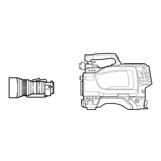
2-1 Accessory Attachments Grip 1 Shoulder strap fitting post 2 Viewfinder front-rear positioning lever 3 Viewfinder left-right positioning lever 4 Lens cable clamp 5 Lens fixing lever 6 Lens mount cap 7 Lens mount Shoulder pad 8 Tripod mount 9 LENS connector 1 Shoulder strap fitting post 6 Lens mount cap Attach one end of a shoulder strap to this fitting post,... -
Page 76: Controls And Connectors
2-2 Controls and Connectors 2-2 Controls and Connectors Front (Right) 1 INCOM button 2 RET 1 button 3 Y/RGB switch 4 R/G/B switch 5 ASSIGNABLE switch 6 FILTER control 8 CAMERA/VTR switch 9 GAIN switch 0 OUTPUT/AUTO KNEE switch qa WHITE BAL switch 7 AUTO W/B BAL switch qs DISPLAY switch qd CANCEL/STATUS switch... - Page 77 7 AUTO W/B BAL (white and black balance OUTPUT AUTO KNEE Function automatic adjustment) switch BARS Output is a color bar signal. Used to automatically adjust white and black balance. Output is the camera’s video signal. WHT: Automatically adjust white balance. The auto knee circuit is disabled.
- Page 78 2-2 Controls and Connectors qd CANCEL/STATUS switch qf MENU SEL (menu select) knob/ENTER button When a menu is displayed on the viewfinder screen, (rotary encoder) pressing this button will cancel any changed setting Used to select settings from menus displayed on the and return the display to the previous menu.
- Page 79 4 MIC IN (microphone input) switch Select either the microphone connected to the MIC 1 IN connector or that connected to the AUDIO IN CH-1 connector on the back. +48V/FRONT: To use the microphone connected to the MIC1 IN connector and supply a power of +48 V to the microphone.
- Page 80 2-2 Controls and Connectors Back (Left) 1 TALLY lamp and TALLY switch 2 CCU connector 3 INCOM1 and 2 connectors 8 RET CONT connector 4 EARPHONE jack 5 TRACKER connector 9 EXT I/O connector 0 REMOTE connector 6 GENLOCK IN/RET IN/ PROMPTER OUT qa DC OUT connector connector and switch...
- Page 81 7 AUDIO IN (auido input 1, 2) connectors (BNC qa DC OUT (DC power supply output) connector type) and switches (4-pin) Connect audio signals. An input select switch and Used to supply power to devices such as a wireless microphone power switch are provided for each receiver (optional).
- Page 82 2-2 Controls and Connectors Back (Right) Shoulder strap fitting (see page 2-1(E)) 3 RET 1 button 4 RET button and select switch 5 INCOM1/2 controls and switches 6 CALL button 1 Memory stick section 2 POWER switch 1 Memory stick section 3 RET 1 (return video 1) button A slot to accomodate a memory stick and an eject The return video 1 signal from the camera control unit...
- Page 83 INCOM 1 INCOM 2 (same components as those of INCOM 1) PGM control and select switch PROD PROD Line select switch INCOM INCOM LEVEL TALK LEVEL TALK LEVEL/TALK switch INCOM INCOM INCOM control PGM (program) control and switch: Adjust the program audio reception level.
-
Page 85: Precautions
3-1 Precautions Do not subject to severe shocks Damage to the case or internal components may result. When finished using Turn off the power switch. Operation and storage environment Store in a level place with air conditioning. Avoid use or storage in the following places: •... -
Page 86: Connections And Power Supply
3-2 Connections and Power Supply Connecting a camera control unit or 3-2-1 Connections remote control panel A VTR, camera control unit, remote control panel, or You can connect an HDCU-900/950 HD Camera an HDCD-50 HD signal distributor can be connected Control Unit or RCP-700-series Remote Control Panel to this camera. -
Page 87: Power Supply
About color bar or test signal output Using a battery pack When performing auto-setup using a remote control panel or master setup unit, setup may be performed To supply power from a battery pack, set the POWER during the output of a color bar or test signal. After switch to EXT and attach a battery adaptor or battery setup is complete, the color bar or test signal will again case to the camera. -
Page 88: Attaching A Lens
3-3 Attaching a Lens The procedure for attaching a lens to the camera is as For information on handling lenses, refer to the lens’ operation manual. follows. Push the lens fixing lever upwards and remove the Connect the lens cable to the LENS connector. lens mount cap from the lens mount. -
Page 89: Adjusting The Flange Focal Length
3-4 Adjusting the Flange Focal Length Adjustment of the flange focal length is necessary in Note the following situations. The various parts of the lens used in adjusting the • The first time a lens is attached flange focal length are in different positions on •... -
Page 90: Adjusting The Viewfinder Position
3-5 Adjusting the Viewfinder Position The viewfinder position may be adjusted towards the When storing the camera in a carrying front and rear and to the left and right to make it easy case to see into it. Move the viewfinder as far as possible towards the microphone side and tighten the viewfinder left-right Adjusting to left or right positioning ring before storing the camera. - Page 91 Keeping the viewfinder from hitting your To keep the viewfinder from bumping your leg when carrying the camera, install the BKW-401 Viewfinder Rotation Bracket (optional) and rotate the viewfinder upwards. Note Lock the viewfinder in a slightly forward position before rotating it upwards. If the viewfinder is in its rearmost position, the arm of the viewfinder rotation bracket will strike the grip.
-
Page 92: Mounting The Camera On A Tripod
3-6 Mounting the Camera on a Tripod To mount the camera on a tripod using the optional VCT-14 Tripod Adaptor, proceed as follows. Mount the tripod adaptor on the tripod. Choose one of the holes in the bottom of the tripod adaptor, taking into account the center of gravity of Tripod adaptor the camera and tripod adaptor. -
Page 93: Attaching A Shoulder Strap
3-7 Attaching a Shoulder Strap Attach an optional shoulder strap to the shoulder strap To attach the shoulder strap fitting posts to use the camera slung over a shoulder. Clip Pull the strap upwards to secure it. Shoulder belt mount point To remove the shoulder strap Press here and move the clip in... -
Page 95: Adjusting The Black Balance And White Balance
4-1 Adjusting the Black Balance and White Balance In order to maintain high picture quality when using Procedure for adjusting the black balance the camera, it is necessary to set the black balance and white balance appropriately for the conditions. Set the switches as shown in the figure below. - Page 96 4-1 Adjustments and Settings for Recording When the GAIN and WHITE BAL switch settings Notes are changed, messages reflecting the new settings • During black balance adjustment, the iris will be will be displayed for approximately three seconds automatically closed. in the setting change/adjustment progress message •...
- Page 97 When automatic white balance adjustment Adjust the lens iris opening. fails With a manually adjusted lens: Set the opening to an appropriate value. With a lens which has automatic iris control: If the white balance adjustment process does not end Set the lens’...
-
Page 98: Setting The Electronic Shutter
4-2 Setting the Electronic Shutter This section explains the different modes which can be 4-2-2 Selecting the Shutter Mode used for the electronic shutter, and gives the and Speed procedures for setting the shutter mode and shutter speed. The shutter mode, and the shutter speed in standard mode, are set using the SHUTTER switch. - Page 99 When shipped from the factory, the camera is set up such that all modes and speeds in the table of “Shutter modes and speeds” on this page will be displayed. However, the camera may be set so that only the necessary modes and speeds are displayed.
-
Page 100: Viewfinder Screen Setup Menu Displays
4-3 Viewfinder Screen Setup Menu Displays When the DISPLAY switch is set to MENU, the The TOP menu has the following sub-menus: OPERATION menu will be displayed on the USER menu viewfinder screen. The OPERATION menu is displayed one page at a time. This menu allows you to register items used frequently. - Page 101 DIAGNOSIS menu Push the MENU SEL knob/ENTER button. This menu displays self-diagnosis information. The setting items for the selected page will be To return to the TOP menu displayed, with an arrow (c) marking the currently The following two methods are available. selected item.
- Page 102 4-3 Viewfinder Screen Setup Menu Displays To change to another page Move the arrow marker (c) to the page number, and press MENU SEL knob/ENTER button. When the arrow marker (c) is located anywhere off the page number, push the STATUS/CANCEL switch towards CANCEL.
-
Page 103: Viewfinder Screen Status Display
4-4 Viewfinder Screen Status Display Besides the video image, the viewfinder can display About display item selection see “4-6-1 Selecting Display Items” on page 4-16(E), and about marker display settings text and messages showing the camera settings and see “4-6-3 Setting Marker Display” on page 4-18(E). operation status, as well as items such as a center marker or safety zone marker. - Page 104 4-4 Viewfinder Screen Status Display 7 Gain value Displays the video gain value (dB) set with the GAIN switch. 8 Focus position Shows the focus position of a zoom lens as a numeric value (0 to 255 (infinity)). 9 Battery voltage Displays the input voltage.
-
Page 105: Using The User Menu
4-5 Using the USER Menu You can select desired pages from the OPERATION, PAINT, MAINTENANCE, FILE, and DIAGNOSIS menu pages, and copy and set them on the USER Menu. If you set pages frequently used on the USER Menu, you can easily call the pages and use them. On the USER Menu, USER PAGE 1 through USER PAGE 5 are provided. -
Page 106: Setting Desired Menu Pages On The User Menu
4-5 Using the USER Menu 3 Turn the MENU SEL knob/ENTER button to The operation select screen appears. select a menu page to be set, then push the MENU SEL knob/ENTER button. Turn the MENU SEL knob/ENTER button to select DELETE, then push the MENU SEL knob/ The selected menu page is set on the USER Menu, and ENTER button. - Page 107 To select items 11 and after 1 Turn the MENU SEL knob/ENTER button to move the arrow (c) to the figure at the top of the screen, then push the MENU SEL knob/ ENTER button. The arrow marker (c) changes to the “?” mark. 2 Turn the MENU SEL knob/ENTER button until a desired item appears, then push the MENU SEL knob/ENTER button.
-
Page 108: Displaying The User Menu
4-5 Using the USER Menu 4-5-3 Displaying the USER Menu You can display and use the USER menu you set in the same manner as the other menus. Display the TOP MENU screen. For details on displaying the TOP MENU screen, see "To display the TOP MENU screen”... -
Page 109: Setup Using The Operation Menu
4-6 Setup Using the OPERATION Menu The items that can be setup or adjusted by using the To set up or adjust the HDC-950/930, use the OPERATION menu are shown below. OPERATION menu. Items which can be adjusted or set using the setup menus Adjustment or setup item Page Page name... -
Page 110: Selecting Display Items
4-6 Setup Using the OPERATION Menu The display items which may be turned on or off 4-6-1 Selecting Display Items using the VF DISPLAY page are: Item Contents Selection of items to be displayed on the viewfinder Extender indicator screen is done using the VF DISPLAY page of the OPERATION menu. -
Page 111: Selecting The Items For Which An '!' Mark To Light
SHUTT When the electronic shutter is used 4-6-2 Selecting the Items for When FAN mode setting with the Which an ‘!’ Mark to Light MAINTENANCE menu is other than AUTO1 Use the ‘!’ IND page of the OPERATION menu to When the lens extender is in use. -
Page 112: Setting Marker Display
4-6 Setup Using the OPERATION Menu Item Condition to unlight MARKER page Type of ND filter (one or more can be specified among 1 to 5) <MARKER> Type of ND filter (one or more can be MARKER specified among A to E) CENTER SAFETY ZONE: 90.0%... -
Page 113: Setting Up The Viewfinder
The arrow marker (c) changes to a question The current setting of each item appears to the mark (?). right of the item. 2 Turn the MENU SEL knob/ENTER button to Item Contents select the desired setting, then press the MENU Sets the gain value selected when the SEL knob/ENTER button. -
Page 114: Setting Up The Auto Iris
4-6 Setup Using the OPERATION Menu 4-6-6 Setting up the Auto Iris Rotate the MENU SEL knob/ENTER button to display the ZEBRA/VF DTL page, and push the MENU SEL knob/ENTER button. The AUTO IRIS page of the OPERATION menu is used to set up items related to the auto iris. -
Page 115: Displaying The Power Voltage
The current status of each item appears to the right Rotate the MENU SEL knob/ENTER button to of the item. change the setting to the desired value, and push Item Contents the MENU SEL knob/ENTER button. TYPE Shows the input power source The “?”... -
Page 116: Using Operator Files
4-6 Setup Using the OPERATION Menu To set the values for another items, repeat steps 3 LENS VTR S/S Assigns a function to the VTR START/STOP button of the lens. and 4. ZOOM DISP Sets the display position (RIGHT or LEFT) of the zoom position on the When the menu operation is completed, set the viewfinder. - Page 117 LENS FILE page <LENS FILE> FILE:c 1 HA14x8 F2.0 The name and f-stop (iris setting) of the currently selected file are displayed. Press the MENU SEL knob/ENTER button. The arrow marker (c) changes to a “?” mark. Turn the MENU SEL knob/ENTER button to select the required file number, then press the MENU SEL knob/ENTER button.
-
Page 118: Paint Menu
4-7 PAINT Menu 4-7 PAINT Menu The PAINT menu contains a collection of paint To reset a PAINT menu item to its adjustment items, such as white adjustment. standard (factory) setting on each page Up to five groups of painting data (scene files) may be saved for scenes to be shot (SCENE FILE page). - Page 119 PAINT menu items Page Setting item Allowable settings Description SW STATUS FLARE ON, OFF Turns flare correction on or off. GAMMA ON, OFF Turns gamma correction on or off. BLK GAM ON, OFF Turns black gamma correction on or off. KNEE ON, OFF Turns knee correction on or off.
- Page 120 4-7 PAINT Menu Page Setting item Allowable settings Description BLK GAMMA RGB LEVEL –99 to 0 to 99 Adjusts the R, G, B, and master black gamma. RGB RANGE 1, 2, 3, 4 Sets the upper limit of the video level which the RGB black gamma affects.
- Page 121 Page Setting item Allowable settings Description USER MATRIX R–G, B–G –99 to 0 to 99 Sets arbitrary R-G or R-B user-set matrix coefficients. G–R, G-B –99 to 0 to 99 Sets arbitrary G-R or G-B user-set matrix coefficients. B–R, B–G –99 to 0 to 99 Sets tarbitrary B-R or B-G user-set matrix coefficients.
- Page 122 4-7 PAINT Menu Page Item Description SCENE FILE Saves and restores a scene file (detail-adjusted data customized to certain shooting scenes). FILE STORE STANDARD Clears all the current detail-adjusted settings and switch settings and returns the settings to the reference file data. READ (MS→CAM) Reads five scene files saved in the memory stick into the memory of the camcorder.
-
Page 123: Shooting Operations
5-1 Shooting Operations To fully utilize the features of this camera, test it Point the camera at the subject and adjust the focus before beginning a shooting (recording) and make sure and zoom. that it is operating properly. Set the shutter speed and mode as necessary. For information on this testing, see “Testing the Camera Before Shooting”... - Page 124 5-1 Shooting Operations Set the ZEBRA switch to ON or MOMENT (momentary). A zebra pattern will be displayed on the viewfinder screen. If the switch is set to MOMENT, the zebra pattern will disappear after five to six seconds. ZEBRA ZEBRA switch MOMENT Set the lens iris appropriately.
- Page 125 Specifications Imager Optical system specifications Imager HDC-950: -type frame Spectral system F1.4 prism interline transfer CCD Built-in filters Color temperature conversion HDC-930: -type interline filters transfer CCD A: cross filter Method 3-CCD, RGB B: 3200K (clear) × 1080 Effective resolution 1920 C: 4300K (horizontal)
- Page 126 Specifications Laserdiodens egenskaper Optional accessories Material: InGaAsP Våglängd: 1310 ±40 nm BKP-L551 Battery Adaptor Strålningstid: utan avbrott BKW-401 Viewfinder Rotation Bracket Laseruteffekt: 141 µW C-74 Microphone –29 Laserdiodens egenskaper CA-905L Large Lens Adaptor Materiale: InGaAsP CAC-6 Return Video Selector Bølgelengde: 1310 ±40 nm CAC-12 Microphone holder Emisjonslengde:...
- Page 127 Testing the Camera Before Shooting Before beginning shooting, test and adjust the camera (1) Set the SHUTTER switch to ON, and verify and make sure it is operating properly. that the “!” lights up. (2) Repeatedly push the SHUTTER switch from ON to the SEL position, and verify that the Preparations for testing shutter speed and mode displayed on the...
- Page 128 Glossary Specifications Aliasing Pedestal level Sampling is performed in converting an An abbreviation for Flange Focal Length. The standard black level of a video signal analog signal to a digital signal. Aliasing when photographing. Since there is noise is a type of interference distortion which in the black region of the video signal, the Flange focal length can be introduced in the sampling process.
- Page 129 The material contained in this manual consists of information that is the property of Sony Corporation and is intended solely for use by the purchasers of the equipment described in this manual. Sony Corporation expressly prohibits the duplication of any...
- Page 130 Sony Corporation Printed in Japan B&P Company HDC-950/930 (JN, SY) 2003.10.13 2000 3-204-027-05(1)
Need help?
Do you have a question about the MEMORY STICK HDC-950 and is the answer not in the manual?
Questions and answers