Table of Contents
Advertisement
Quick Links
SMARTLINE® RM77
SMARTLINE
SMARTLINE
SMARTLINE
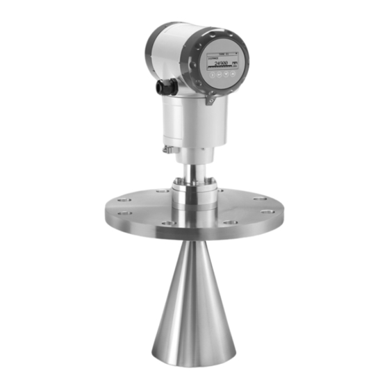
10 GHz Radar (FMCW) Level Meter
for distance, level, volume, flow, mass and reflection measurement of liquids
Safety manual
Safety manual
Safety manual
Safety manual
RM77
RM77
RM77
Supplementary instructions
Supplementary instructions
Supplementary instructions
Supplementary instructions
Advertisement
Table of Contents

Related Manuals for Honeywell SMARTLINE RM77


Summary of Contents for Honeywell SMARTLINE RM77
- Page 1 SMARTLINE SMARTLINE® RM77 RM77 SMARTLINE SMARTLINE RM77 RM77 Supplementary instructions Supplementary instructions Supplementary instructions Supplementary instructions 10 GHz Radar (FMCW) Level Meter for distance, level, volume, flow, mass and reflection measurement of liquids Safety manual Safety manual Safety manual Safety manual...
-
Page 2: Table Of Contents
7.5.2 Limits for supervisor menu functions related to device configuration ....... 23 8 Service 8.1 Periodic maintenance..................... 27 8.2 Keep the device clean..................... 27 8.3 Availability of services ....................27 8.4 Proof tests ........................27 www.honeywell.com/ps 34-VF-25-105 iss.1 GLO April 15 US... - Page 3 9.3 Characteristics for the device safety function ............... 36 9.4 SIL-specific technical data ..................... 36 9.5 Support for SIL-approved devices.................. 38 10 Appendix 10.1 Start-up report ......................39 10.2 Proof test report form (for copying) ................40 34-VF-25-105 iss.1 GLO April 15 US www.honeywell.com/ps...
- Page 4 CONTENTS SMARTLINE® RM77 www.honeywell.com/ps 34-VF-25-105 iss.1 GLO April 15 US...
-
Page 5: Introduction
INFORMATION! Installation, commissioning and maintenance may only be carried out by approved personnel. 1.2 Revision history Edition Date Description April 28, 2015 First issue. 34-VF-25-105 iss.1 GLO April 15 US www.honeywell.com/ps... -
Page 6: Device Description
[N3] NAMUR Recommendation NE 043 Standardization of the Signal Level for the Failure Information of Digital Transmitters [N4] NAMUR Recommendation NE 053 Software of Field Devices and Signal Processing Devices with Digital Electronics [N5] SmartLine® RM77 Supplementary Instructions for ATEX applications www.honeywell.com/ps 34-VF-25-105 iss.1 GLO April 15 US... -
Page 7: Terms And Definitions
Proof Test Interval T[Repair] Time to Repair T[Test] Internal Diagnostics Test Interval 1oo1 1 out of 1 channel architecture (single architecture performs the safety function) 1oo1D 1 out of 1 channel architecture with diagnostics 34-VF-25-105 iss.1 GLO April 15 US www.honeywell.com/ps... - Page 8 INTRODUCTION SMARTLINE® RM77 www.honeywell.com/ps 34-VF-25-105 iss.1 GLO April 15 US...
-
Page 9: System Description
2.2 Software for use with the device You can change device parameters with the software that follows: • PACTware™ • AMS™ Device Manager For more data, refer to "Start-up" in the handbook (document [N1]). 34-VF-25-105 iss.1 GLO April 15 US www.honeywell.com/ps... - Page 10 SYSTEM DESCRIPTION SMARTLINE® RM77 www.honeywell.com/ps 34-VF-25-105 iss.1 GLO April 15 US...
-
Page 11: Installation
DN100, DN150 and DN200 Metallic Horn antennas) or the Wave-Guide antenna This maintenance task must be done and recorded by approved personnel. For more data, refer Calibration procedure on page 30. For more data, refer to "Installation" in the handbook (document [N1]). 34-VF-25-105 iss.1 GLO April 15 US www.honeywell.com/ps... - Page 12 INSTALLATION SMARTLINE® RM77 www.honeywell.com/ps 34-VF-25-105 iss.1 GLO April 15 US...
-
Page 13: Electrical Connection
If the device is to agree with the requirements for functional safety given in IEC 61508, you must obey the electrical connection instructions given in the handbook (document [N1]). The device must be installed by approved personnel. For more data, refer to “Electrical connection” in the handbook (document [N1]). 34-VF-25-105 iss.1 GLO April 15 US www.honeywell.com/ps... - Page 14 ELECTRICAL CONNECTION SMARTLINE® RM77 www.honeywell.com/ps 34-VF-25-105 iss.1 GLO April 15 US...
-
Page 15: Start-Up
For more data about device configuration, refer to the "Start-up" and "Operation" chapters in the User parameters handbook (document [N1]). Also refer to on page 22. 34-VF-25-105 iss.1 GLO April 15 US www.honeywell.com/ps... - Page 16 START-UP SMARTLINE® RM77 www.honeywell.com/ps 34-VF-25-105 iss.1 GLO April 15 US...
-
Page 17: Specification Of Safety Function
International Standard IEC 61508 Part 2 (document [N2]), section 7.4.4.1.4. • Use DN80 and DN100 Metallic Horn antenna only in stilling wells as specified in the handbook (document [N1]). SIL-specific technical data For more data, refer to on page 36. 34-VF-25-105 iss.1 GLO April 15 US www.honeywell.com/ps... -
Page 18: Safety Function Characteristics
Error signal Error signal Error signal Error signal If a logic solver is used, it must use low error alarm signals (current input ≤ 3.6 mA) to set itself to a fail-safe condition. www.honeywell.com/ps 34-VF-25-105 iss.1 GLO April 15 US... -
Page 19: Operation
(≤ 3.6 mA). Thus, the output signal Limits for supervisor menu for the fail-safe condition is less than 3.6 mA. For more data, refer to functions related to device configuration on page 23 (2.4.2 RANGE I). 34-VF-25-105 iss.1 GLO April 15 US www.honeywell.com/ps... -
Page 20: Operation Mode
Yes. A correct measurement is available. Error mode state Current output (distance value or a derived measurement value) Is the current output setting correct? No. The current output setting is incorrect. Yes. The current output setting is correct. www.honeywell.com/ps 34-VF-25-105 iss.1 GLO April 15 US... -
Page 21: Error Conditions
"YES", there is a risk that the product will overflow and cover the antenna. For more data, refer to the "Status and error messages" section in the handbook (document [N1]). 34-VF-25-105 iss.1 GLO April 15 US www.honeywell.com/ps... -
Page 22: User Parameters
Guide antenna, enter the 2.3.1 TANK HEIGHT height. The device will use this data if you set 2.3.4 STILLWELL EN. to "YES". This menu item is not shown if you set 2.3.4 STILLWELL EN. to "NO". www.honeywell.com/ps 34-VF-25-105 iss.1 GLO April 15 US... -
Page 23: Limits For Supervisor Menu Functions Related To Device Configuration
Conversion parameters are shown if there is volume or mass data in 2.8.1 INPUT TABLE. 34-VF-25-105 iss.1 GLO April 15 US www.honeywell.com/ps... - Page 24 "Direct mode and "TBF" mode. If you use "TBF Full" or "TBF Partial", enter the dielectric constant in menu item 2.5.3 Er PRODUCT. www.honeywell.com/ps 34-VF-25-105 iss.1 GLO April 15 US...
- Page 25 2.3.2) and the flange. But condensation or other sources of parasitic signals can cause an "overfill" error. If you set this menu item to "YES", make sure that there are no sources of parasitic signals near to the flange. 34-VF-25-105 iss.1 GLO April 15 US www.honeywell.com/ps...
- Page 26 OPERATION SMARTLINE® RM77 www.honeywell.com/ps 34-VF-25-105 iss.1 GLO April 15 US...
-
Page 27: Service
• The location of the device and how it is installed on the tank can have an effect on the performance. Make sure that you obey the installation instructions given in the handbook. 34-VF-25-105 iss.1 GLO April 15 US www.honeywell.com/ps... - Page 28 Make sure that this menu item is set to 0 0 0 0 . If the value is not set to 0 0 0 0 , the safety function will not operate correctly. www.honeywell.com/ps 34-VF-25-105 iss.1 GLO April 15 US...
- Page 29 It is only necessary to measure the level and current output of the product in the tank when it is full (without overfill) and 50% full. 34-VF-25-105 iss.1 GLO April 15 US www.honeywell.com/ps...
-
Page 30: Calibration Procedure
Do not connect the ammeter across the safety system PLC because this configuration can open the circuit breaker. Make sure that the 2 reference points are not in the top or bottom dead zones. www.honeywell.com/ps 34-VF-25-105 iss.1 GLO April 15 US... -
Page 31: Current Output Check
• End of the procedure. CAUTION! If the values do not agree with the tolerances, then the data supplied by device will not be correct. For a solution to the problem, speak to the supplier. 34-VF-25-105 iss.1 GLO April 15 US www.honeywell.com/ps... -
Page 32: Measuring Range Check (In Process Conditions)
To change the device settings to get satisfactory results, speak to the supplier. SIL-specific technical data For more data about reference conditions, refer to on page 36. www.honeywell.com/ps 34-VF-25-105 iss.1 GLO April 15 US... -
Page 33: Troubleshooting
• such dangerous substances, to enclose a certificate with the device confirming that is safe to handle and stating the • product used. 34-VF-25-105 iss.1 GLO April 15 US www.honeywell.com/ps... -
Page 34: Form (For Copying) To Accompany A Returned Device
We have flushed out and neutralized all cavities in the device. We hereby confirm that there is no risk to persons or the environment through any residual media contained in the device when it is returned. Date: Signature: Stamp: www.honeywell.com/ps 34-VF-25-105 iss.1 GLO April 15 US... -
Page 35: Technical Data
T[Proof] is from 1 to 10 years (87600 hours) • T[Repair] is 72 hours • T[Test] is 24 hours (all internal test functions are done a minimum of one time during this • period) 34-VF-25-105 iss.1 GLO April 15 US www.honeywell.com/ps... -
Page 36: Characteristics For The Device Safety Function
2-wire loop-powered level transmitter; X-band (10 GHz) FMCW radar Application range Level measurement of liquids, pastes and slurries Primary measured value Distance and reflection measurement of 1 product Secondary measured value Distance, level, volume, mass and flow rate www.honeywell.com/ps 34-VF-25-105 iss.1 GLO April 15 US... - Page 37 PTFE Wave Horn antenna: Stainless steel (1.4404 / 316L) with a PTFE plate / lining Metallic Horn antenna: Stainless steel (1.4404 / 316L); other materials on request Wave Guide antenna: Stainless steel (1.4404 / 316L) 34-VF-25-105 iss.1 GLO April 15 US www.honeywell.com/ps...
-
Page 38: Support For Sil-Approved Devices
2 When only one liquid is in the tank 9.5 Support for SIL-approved devices If the manufacturer makes a modification that has an effect on the safety function of the device, the manufacturer will tell you about the modification immediately. www.honeywell.com/ps 34-VF-25-105 iss.1 GLO April 15 US... -
Page 39: Appendix
Are the process temperature and pressure in the limits for operation of the device? Did you correctly install the device on the tank? Do the electrical connections agree with the national electrical codes? I hereby confirm that I have completed the start-up checklist. Date: Signature: Stamp: 34-VF-25-105 iss.1 GLO April 15 US www.honeywell.com/ps... -
Page 40: Proof Test Report Form (For Copying)
3 The tank is full when menu item 2.4.1 OUTPUT FUNC.= Level. The tank is empty when menu item 2.4.1 OUTPUT FUNC.= Distance. Conclusion Does the device operate satisfactorily in safety-related systems? [Yes] [No] Signature: www.honeywell.com/ps 34-VF-25-105 iss.1 GLO April 15 US... - Page 41 APPENDIX SMARTLINE® RM77 34-VF-25-105 iss.1 GLO April 15 US www.honeywell.com/ps...
- Page 42 Houston, TX 77042 Houston, TX 77042 www.honeywellprocess.com www.honeywellprocess.com www.honeywellprocess.com www.honeywellprocess.com © Honeywell International Inc. © Honeywell International Inc. © Honeywell International Inc. © Honeywell International Inc. Subject to change without notice. Subject to change without notice. Subject to change without notice.
Need help?
Do you have a question about the SMARTLINE RM77 and is the answer not in the manual?
Questions and answers