ABB ACS800-04 Hardware Manual
Drive modules
Hide thumbs
Also See for ACS800-04:
- Hardware manual (118 pages) ,
- Cabinet installation and operating instruction (162 pages) ,
- Installation manual (52 pages)

Related Manuals for ABB ACS800-04


Summary of Contents for ABB ACS800-04
- Page 1 — ABB INDUSTRIAL DRIVES ACS800-04/-04M (45 to 560 kW) ACS800-U4 (60 to 600 hp) drive modules Hardware manual...
- Page 2 — List of related manuals Drive hardware manuals and guides Code (English) ACS800-04/04M/U4 Drive Modules (45 to 560 kW, 60 to 600 3AFE64671006 hp) Hardware Manual ACS800-04/04M/U4 Drive Modules (45 to 560 kW, 60 to 600 3AFE68360323 hp) Cabinet Installation...
- Page 3 ACS800-04/-04M (45 to 560 kW) ACS800-U4 (60 to 600 hp) drive modules Hardware manual Table of contents 1. Safety instructions 4. Mechanical installation 6. Electrical installation 9. Start-up and use 3AFE64671006 Rev H EFFECTIVE: 2023-12-01 2023 ABB. All Rights Reserved.
-
Page 5: Table Of Contents
ACS800-04/U4 product overview ........ - Page 6 6 Table of contents Cooling air flow ............35 Cable channel in the floor below the cabinet .
- Page 7 Table of contents 7 7. Electrical installation What this chapter contains ........... 63 Checking the insulation of the assembly .
- Page 8 8 Table of contents Removing the control panel ..........87 11.
- Page 9 How to select the correct drive/chopper/resistor combination ....132 Optional brake chopper and resistor(s) for the ACS800-04/04M/U4 ... 133 Resistor installation and wiring .
- Page 10 10 Table of contents...
-
Page 11: Safety Instructions
Safety instructions 11 Safety instructions What this chapter contains This chapter contains the safety instructions that you must obey when you install, operate and service the drive. If you ignore them, physical injury or death may occur, or damage may occur to the drive, motor or driven equipment. Read the safety instructions before you do work on the unit. -
Page 12: Installation And Maintenance Work
12 Safety instructions Installation and maintenance work These warnings are intended for all person that do work on the drive, motor cable or motor. WARNING! If you ignore these safety instructions, physical injury or death, or damage to the equipment can occur: •... -
Page 13: Grounding
Safety instructions 13 • At installation sites that are above 2000 m (6562 ft), the terminals of the RMIO board and option modules attached to the board do not fulfill the Protective Extra Low Voltage (PELV) requirements in EN 50178. Grounding ... -
Page 14: Mechanical Installation And Maintenance
14 Safety instructions Mechanical installation and maintenance These instructions are intended for all persons that install and service the drive. WARNING! If you ignore these instructions, physical injury or death, or damage to the equipment can occur: • Handle the unit carefully. •... -
Page 15: Fiber-Optic Cables
Safety instructions 15 Fiber-optic cables WARNING! If you ignore these instructions, it can cause equipment malfunction and damage to the fiber-optic cables: Handle the fiber-optic cables with care. When you disconnect fiber-optic cables, always hold the connector, not the cable. Do not touch the ends of the fibers with bare hands as the fiber is extremely sensitive to dirt. -
Page 16: Permanent Magnet Motor
16 Safety instructions Permanent magnet motor These are additional warnings for permanent magnet motor drives. If you ignore the instructions, physical injury or death, or damage to the equipment can occur. Control a permanent magnet motor only with the ACS800 Permanent Magnet Synchronous Motor Drive Control Program. -
Page 17: Introduction To This Manual
Introduction to this manual 17 Introduction to this manual What this chapter contains This chapter describes the intended audience and contents of this manual. It has a flowchart of steps to check the delivery, install and commission the drive. The flowchart refers to sections in this manual and in other documents. -
Page 18: Categorization According To The Plus Code
Resistor braking (page 131) describes how to select, protect and wire optional brake choppers and resistors. The chapter also contains technical data. Non-ABB du/dt filter selection (page 139) contains guidelines on selecting and installing a non-ABB d filter with the drive. -
Page 19: Installation, Commissioning And Operating Flowchart
Introduction to this manual 19 Installation, commissioning and operating flowchart Task Technical data Identify the frame size of your drive, R7 or R8. (page 99) Technical data Plan the installation. (page 99) Planning the electrical installation Check the ambient conditions, ratings, required (page 37) cooling air flow, input power connection, Option manual (if optional equipment is included) - Page 20 20 Introduction to this manual Task Resistor braking Commission the optional brake chopper (if (page 131) present). Operating of the drive: start, stop, speed control Appropriate firmware manual etc.
-
Page 21: Terms And Abbreviations
Introduction to this manual 21 Terms and abbreviations Term / Abbreviation Description AGPS Power supply board for IGBT gate driver boards. Used in implementation of the optional Prevention of unexpected start-up function. AIMA I/O module adapter. An extension unit for mounting I/O extension modules outside the drive unit. - Page 22 22 Introduction to this manual...
-
Page 23: Operation Principle And Hardware Description
Operation principle and hardware description 23 Operation principle and hardware description What this chapter contains This chapter describes the construction and operating principle of the drive. -
Page 24: Acs800-04/U4 Product Overview
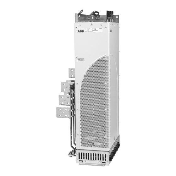
24 Operation principle and hardware description ACS800-04/U4 product overview The ACS800-04/U4 is an IP00 drive module used to control AC motors. It is designed to be installed into a cabinet with base or wall fastening. The input cable terminals are at the top of the unit and the motor cable terminals are located at the left or right side of the unit. -
Page 25: Acs800-04M Product Overview
Operation principle and hardware description 25 ACS800-04M product overview The ACS800-04M is delivered as non-pre-assembled kits, which provide more alternatives in assembling the units than the basic ACS800-04. Example configurations Frame size R7 Motor and brake busbars on the... -
Page 26: Type Designation Label
26 Operation principle and hardware description Type designation label The type designation label has an IEC and NEMA rating, C-UL US, and CSA markings, a type code and a serial number, which allow individual recognition of each unit. The first digit of the serial number refers to the manufacturing plant. The next four digits refer to the manufacturing year and week, respectively. -
Page 27: Type Code
The type code contains information on the specifications and configuration of the drive. The first digits from left express the basic configuration (for example, ACS800-04-0170-5). The optional selections are given thereafter, separated by plus signs (for example, +E202). The main selections are described below. Not all ACS800 Ordering selections are available for all types. - Page 28 600 mm (23.62 in.) cable outside the drive module in frame size R8. Note: Type code +0N664 means that the drive module has been installed inside a cabinet at the factory. This type code is for ABB internal use only.
-
Page 29: Main Circuit And Control Interfaces
Operation principle and hardware description 29 Main circuit and control interfaces Diagram This diagram shows the control interfaces and the main circuit of the drive. Motor Optional module 1: RMBA, RAIO, RDIO, control RDNA, RLON, RIBA, RPBA, RCAN, RCNA, and I/O RMBP, RETA, RRIA or RTAC board... -
Page 30: Printed Circuit Boards
30 Operation principle and hardware description Printed circuit boards The drive contains the following printed circuit boards as standard: • main circuit board (AINT) • motor control and I/O board (RMIO) with a fiber-optic link to the AINT board •... -
Page 31: Connections Of The Rdcu Control Unit
Operation principle and hardware description 31 Connections of the RDCU control unit ACS800-04 drive module Protective tube AINT 3 m (118 in.) Shield APOW 2100 mm (83 in.) Shielded 6-pin To RMIO modular connector Control panel mounting platform kit (RPMP-11,... - Page 32 32 Operation principle and hardware description...
-
Page 33: Mechanical Installation
For the mechanical assembly and ACS800-04/04M/U4 Cabinet dimensional drawings of the drive module, refer to Installation ACS800-04/04M/U4 Drive Modules (45 to [3AFE68360323 (English)] and 560 kW, 60 to 600 hp) Rittal TS 8 Cabinet Installation [3AFE68372330 (English)]. -
Page 34: Before Installation
To unpack the package, cut the bands (A) and remove the outer box (B) and sleeve (C). Note: This figure shows the package of an ACS800-04 module, frame size R7. There can also be additional accessory boxes that are not shown in the figure. -
Page 35: Cooling Air Flow
Mechanical installation 35 Cooling air flow Provide the drive with the amount of clean cooling air given in IEC data (page 99) or NEMA data (page 114). Cable channel in the floor below the cabinet When a cable channel is constructed below the cabinet, make sure that the cabinet weight is on the sections that the floor carries. - Page 36 36 Mechanical installation...
-
Page 37: Planning The Electrical Installation
The installation must always be designed and done according to applicable local laws and regulations. ABB does not assume any liability whatsoever for any installation which breaches the local laws and/or other regulations. Furthermore, if the recommendations given by ABB are not followed, the drive may experience problems that the warranty does not cover. -
Page 38: Motor Selection And Compatibility
38 Planning the electrical installation Motor selection and compatibility Technical data Select the motor according to the rating tables in (page 99). Use the DriveSize PC tool if the default load cycles are not applicable. 2. Make sure that the motor ratings are in the allowed ranges of the drive control program: •... -
Page 39: Protecting The Motor Insulation And Bearings
Modern variable speed drives with their fast rising voltage pulses and high switching frequencies can generate current pulses that flow through the motor bearings, which can gradually erode the bearing races and rolling elements. The stress on motor insulation can be avoided by using optional ABB d filters. The d filters also reduce bearing currents. -
Page 40: Requirements Table
The following table shows how to select the motor insulation system and when an optional ABB d filter, insulated N-end (non-driven end) motor bearings and ABB common mode filters are required. Ignoring the requirements or improper installation may shorten motor life or damage the motor bearings and voids the warranty. - Page 41 Planning the electrical installation 41 Motor Nominal mains Requirement for type voltage (AC line Motor insulation ABB d filter, insulated N-end bearing and ABB voltage) system common mode filter < 100 kW 100 kW < < > 350 kW 350 kW or frame size >...
- Page 42 Note 3: The rated output power of high output motors is higher than what is stated for the particular frame size in EN 50347:2001. This table shows the requirements for ABB random-wound motor series (for example, M3AA, M3AP and M3BP).
- Page 43 All AMA machines (manufactured in Helsinki) for drive systems have form-wound windings. All HXR machines manufactured in Helsinki starting 1.1.1998 have form- wound windings. ABB motors of types other than M2_, M3_, HX_ and AM_ Note 6: Use the selection criteria given for non-ABB motors.
-
Page 44: Permanent Magnet Motor
(one box with three rings for one cable). Permanent magnet motor Only one permanent magnet motor can be connected to the inverter output. ABB recommends a safety switch between the permanent magnet motor and the drive output. The switch isolates the motor during maintenance work. -
Page 45: Supply Connection
Planning the electrical installation 45 Supply connection Disconnecting device Install a hand-operated input disconnecting device between the AC power source and the drive. The disconnecting device must be of a type that can be locked to the open position for installation and maintenance work. To meet the European Union Directives, according to standard EN/IEC 60204-1, Safety of Machinery, the disconnecting device must be one of the following types: •... -
Page 46: Thermal Overload And Short-Circuit Protection
46 Planning the electrical installation Thermal overload and short-circuit protection Thermal overload protection of the drive and the input and motor cables The drive protects itself and the input and motor cables against thermal overload when the cables are dimensioned according to the nominal current of the drive. No additional thermal protection devices are needed. -
Page 47: Protecting The Motor And Motor Cable In Short Circuits
2) Circuit breakers which have been tested by ABB with the ACS800 can be used. Fuses must be used with other circuit breakers. Contact your local ABB representative for the approved breaker types and supply network characteristics. -
Page 48: Ground Fault Protection
48 Planning the electrical installation Ground fault protection The drive has ground fault protection in the motor and motor cable. This is not a personal safety or a fire protection feature. The ground fault protection can be disabled with a parameter, refer to the applicable firmware manual. The EMC filter of the drive has capacitors between the main circuit and the frame. -
Page 49: Prevention Of Unexpected Start-Up (Option +Q950)
Indicating lamp: on = the drive is disabled, off = drive can operate. • Safety relay (type BD5935 has been approved by ABB) WARNING! The Prevention of unexpected start-up function does not disconnect the voltage of the main and auxiliary circuits from the drive. -
Page 50: Terminal For The User Connection
50 Planning the electrical installation Terminal for the user connection The POUS function includes an AGPS board that is installed at the factory. This figure shows the location of the AGPS board and the terminal for the POUS user connection. -
Page 51: Safe Torque Off (Option +Q967)
Planning the electrical installation 51 Safe torque off (option +Q967) The drive supports the Safe torque off (STO) function according to these standards: • EN 61800-5-2:2007 • EN ISO 13849-1:2008/AC:2009 • EN ISO 13849-2:2012 • IEC 61508 ed. 1 • EN 62061:2005/AC:2010 •... - Page 52 52 Planning the electrical installation The Safe torque off function can be used to stop the drive in emergency stop situations. In the normal operating mode, use the Stop command instead. If the Safe torque off function is activated when the drive is running, the control voltage of the power semiconductors is cut off and the motor coasts to a stop.
-
Page 53: Terminal For The User Connection
Planning the electrical installation 53 Terminal for the user connection The STO function includes an ASTO board that is installed in the drive module at the factory. This figure shows the location of the ASTO board and the terminal for the STO user connection in the drive module. -
Page 54: Selecting The Power Cables
Longer cables cause a motor voltage decrease which limits the available motor power. The decrease depends on the motor cable length and characteristics. Contact ABB for more information. Note that a sine filter (optional) at the drive output also causes a voltage decrease. -
Page 55: Alternative Power Cable Types
Planning the electrical installation 55 Alternative power cable types Power cable types that can be used with the drive are represented below. Recommended A separate PE conductor is required if the Symmetrical shielded cable: three phase conductivity of the cable shield is < 50% conductors and a concentric or otherwise of the conductivity of the phase symmetrically constructed PE conductor, and a... -
Page 56: Additional Us Requirements
56 Planning the electrical installation Additional US requirements Type MC continuous corrugated aluminum armor cable with symmetrical grounds or shielded power cable must be used for the motor cables if metallic conduit is not used. For the North American market, 600 V AC cable is accepted for up to 500 V AC. 1000 V AC cable is required above 500 V AC (below 600 V AC). -
Page 57: Power Factor Compensation Capacitors
Planning the electrical installation 57 Power factor compensation capacitors Power factor compensation is not needed with AC drives. However, if a drive is to be connected in a system with compensation capacitors installed, note the following restrictions. WARNING! Do not connect power factor compensation capacitors or harmonic filters to the motor cables (between the drive and the motor). -
Page 58: Using A Contactor Between The Drive And The Motor
58 Planning the electrical installation Using a contactor between the drive and the motor Implementing the control of the output contactor depends on how you select the drive to operate. When you have selected to use DTC motor control mode, and motor ramp stop, open the contactor as follows: Give a stop command to the drive. -
Page 59: Tive Loads
Planning the electrical installation 59 Protecting the relay output contacts and attenuating disturbances in case of inductive loads Inductive loads (relays, contactors, motors) cause voltage transients when switched off. The relay contacts on the RMIO board are protected with varistors (250 V) against overvoltage peaks. -
Page 60: Selecting The Control Cables
Germany) has been tested and approved by ABB. Control panel cable In remote use, the cable connecting the control panel to the drive must not exceed 3 m (10 ft). The cable type tested and approved by ABB is used in control panel option kits. -
Page 61: Connection Of A Motor Temperature Sensor To The Drive I/O
Planning the electrical installation 61 Connection of a motor temperature sensor to the drive WARNING! IEC 61800-5-1 requires double or reinforced insulation between live parts when: • the accessible parts are non-conductive, or • the accessible parts are conductive, but not connected to the protective earth. -
Page 62: Routing The Cables
62 Planning the electrical installation Routing the cables Route the motor cable away from other cable routes. Motor cables of several drives can be run in parallel installed next to each other. It is recommended that the motor cable, input power cable and control cables be installed on separate trays. Avoid long parallel runs of motor cables with other cables in order to decrease electromagnetic interference caused by the rapid changes in the drive output voltage. -
Page 63: Electrical Installation
Electrical installation 63 Electrical installation What this chapter contains This chapter instructs in the cabling of the drive. WARNING! The work described in this chapter may only be carried out by a Safety instructions qualified electrician. Obey the (page 11) in this manual. Ignoring the safety instructions can cause injury or death. -
Page 64: Motor And Motor Cable
2. Measure the insulation resistance between each phase conductor and the Protective Earth conductor using a measuring voltage of 1000 V DC. The insulation resistance of an ABB motor must exceed 100 Mohm (reference value at 25 °C or 77 °F). For the insulation resistance of other motors, please consult the manufacturer’s instructions. -
Page 65: Example Wiring Diagram
Electrical installation 65 Example wiring diagram The diagram presents an example for the main wiring. The diagram includes optional components which are not part of a basic delivery (marked *) and equipment not available as plus code options (marked **). -
Page 66: Power Cable Connection Diagram
66 Electrical installation Power cable connection diagram Drive module OUTPUT INPUT UDC+ V1 W1 V2 W2 (PE) (PE) External brake resistor * For alternatives, see Disconnecting device Motor (page 45). 1), 2) Grounding of the motor cable shield at the cabinet entry If shielded cable is used (not required but recommended) and the conductivity of the... -
Page 67: Grounding Of The Cable Shields
Electrical installation 67 Grounding of the cable shields To power terminals Example cable lead-through Strain relief Cable shield PE terminal of the cabinet or drive module EMC sleeve * Strip this section * Recommended for control cables Base plate Lead-through plate Strain relief EMI conductive... -
Page 68: Fastening Us Cable Lugs
68 Electrical installation Fastening US cable lugs Example mounting US cable lugs can be connected directly to the output busbars or to the terminals as follows. 1/2” bolt 1 3/4”... -
Page 69: Connections Of The Rdcu
Electrical installation 69 Connections of the RDCU The RDCU control unit contains the RMIO board for the control cables. WARNING! Handle the fiber-optic cables with care. When you disconnect optic cables, always hold the connector. Do not touch the ends of the fibers with bare hands as the fiber is sensitive to dirt. -
Page 70: Connecting The Control Cables To The Rmio Board
70 Electrical installation Connecting the control cables to the RMIO board Connect the control cables as described below. Connect the conductors to the Motor control and I/O appropriate detachable terminals of the RMIO board (refer to board (RMIO) on page 75). Tighten the screws to secure the connection. Make 360- degree EMC grounding at the cabinet entry in first environment installations. -
Page 71: Settings Of The Cooling Fan Transformer
Electrical installation 71 Settings of the cooling fan transformer The voltage transformer of the cooling fan is located at the top right-hand corner of the drive module. Remove the front cover for adjusting the settings and replace the cover after setting. Set to 220 V if the supply frequency is 60 Hz. -
Page 72: Pulse Encoder Module Cabling
72 Electrical installation Pulse encoder module cabling Clamp as close to the terminals as possible. Alternative to a) Strain relief Note1: If the encoder is of unisolated As short as with a cable tie type, ground the encoder cable at possible the drive end only. -
Page 73: Removing The Protective Covering From The Drive Module Air Outlet
Electrical installation 73 Removing the protective covering from the drive module air outlet WARNING! Remove the protective covering from the top of the drive module after the installation. If the covering is not removed, the cooling air cannot flow freely through the module and the drive can get too hot. - Page 74 74 Electrical installation...
-
Page 75: Motor Control And I/O Board (Rmio)
Motor control and I/O board (RMIO) 75 Motor control and I/O board (RMIO) What this chapter contains This chapter shows the • External control connections to the RMIO board for the ACS800 Standard Control Program (Factory Macro). • Specifications of the inputs and outputs of the board. Note on terminal labelling Optional modules (Rxxx) may have identical terminal designations with the RMIO board. -
Page 76: Note On External Power Supply
76 Motor control and I/O board (RMIO) Note on external power supply An external +24 V DC power supply for the RMIO board is recommended if • the application requires a fast start after connecting the input power supply • fieldbus communication is required when the input power supply is disconnected. -
Page 77: External Control Connections (Non-Us)
Motor control and I/O board (RMIO) 77 External control connections (non-US) External control cable connections to the RMIO board for the ACS800 Standard Control Program (Factory Macro) are shown below. For external control connections of other control macros and programs, see the appropriate firmware manual. RMIO RMIO Terminal block size:... -
Page 78: External Control Connections (Us)
78 Motor control and I/O board (RMIO) External control connections (US) External control cable connections to the RMIO board for the ACS800 Standard Control Program (Factory Macro US version) are shown below. For external control connections of other control macros and programs, see the appropriate firmware manual. -
Page 79: Rmio Board Specifications
Motor control and I/O board (RMIO) 79 RMIO board specifications Analogue inputs Two programmable differential current inputs (0 mA / 4 mA ... 20 mA, = 100 ohm) and one programmable differential voltage input (- 10 V / 0 V / 2 V ... +10 V, = 200 kohm). -
Page 80: Relay Outputs
Insulation test voltage 4 kV AC, 1 minute DDCS fiber-optic link With optional communication adapter module RDCO. Protocol: DDCS (ABB Distributed Drives Communication System) 24 V DC power input Voltage 24 V DC ± 10% Typical current consumption... - Page 81 Motor control and I/O board (RMIO) 81 Isolation and grounding diagram (Test voltage: 500 V AC) VREF- AGND VREF+ AGND AI1+ Common mode AI1- voltage between AI2+ channels ±15 V AI2- AI3+ AI3- AO1+ AO1- AO2+ AO2- Jumper J1 settings: DGND1 All digital inputs share a common ground.
- Page 82 82 Motor control and I/O board (RMIO)
-
Page 83: Installation Checklist
Installation checklist 83 Installation checklist What this chapter contains This chapter contains the installation checklist. Checklist Check the mechanical and electrical installation of the drive before start-up. Go Safety through the checklist below together with another person. Read the instructions (page 11) in this manual before you do work on the unit. - Page 84 84 Installation checklist Check The drive is grounded properly. The mains (input power) voltage matches the drive nominal input voltage. The mains (input power) connections at U1, V1 and W1 and their tightening torques are OK. Appropriate mains (input power) fuses and disconnector are installed. The motor connections at U2, V2 and W2 and their tightening torques are OK.
-
Page 85: Start-Up And Use
Start-up and use 85 Start-up and use What this chapter contains This chapter describes the start-up procedure and use of the drive. -
Page 86: Start-Up Procedure
86 Start-up and use Start-up procedure Ensure that the installation of the drive has been checked according to the checklist in the Installation checklist, and that the motor and driven equipment are ready for start. 2. Switch the power on and set-up the drive control program according to the start-up instructions given in the drive firmware manual. -
Page 87: Control Panel
Start-up and use 87 Control panel The user interface of the drive is the control panel (type CDP 312R). For more information on using the control panel, see the firmware manual delivered with the drive. Removing the control panel To remove the control panel from the panel holder, press down the locking clip and pull the panel out. - Page 88 88 Start-up and use...
-
Page 89: Maintenance
Maintenance 89 Maintenance What this chapter contains This chapter contains preventive maintenance instructions. Safety WARNING! Obey the Safety instructions (page 11) in this manual before you do maintenance on the equipment. Ignoring the safety instructions can cause injury or death. -
Page 90: Maintenance Intervals
(depending on the dustiness of and cleaning the environment) Every 6 years Cooling fan replacement (page 92). Every 9 years Capacitor replacement Capacitors (page 95). Consult your local ABB Service representative for more details on the maintenance. On the Internet, go to http://www.abb.com/drives. -
Page 91: Layout
Maintenance 91 Layout The layout stickers of the drive are shown below. The stickers show all possible components. Not all of them are present in each delivery or described here. Components that need to be changed regularly are listed below: Designation Component Cooling fan... -
Page 92: Heatsink
See the appropriate ACS800 firmware manual for the actual signal which indicates the running time of the cooling fan. For resetting the running time signal after a fan replacement, please contact ABB. Replacement fans are available from ABB. Do not use other than ABB specified spare parts. -
Page 93: Replacing The Fan (R7)
Maintenance 93 Replacing the fan (R7) Remove the front cover. 2. Disconnect the discharging resistor wire(s). 3. Remove the DC capacitor pack by undoing the red fixing screws and pulling the pack out. 4. Disconnect the fan supply wires (detachable connector). 5. -
Page 94: Replacing The Fan (R8)
94 Maintenance Replacing the fan (R8) Remove the front cover. 2. Disconnect the fan capacitor and power supply wires. 3. Remove the red fastening screws of the plastic side cover of the fan. Shift the cover to the right to free its right-hand edge and lift the cover off. 4. -
Page 95: Capacitors
It is not possible to predict a capacitor failure. Capacitor failure is usually followed by damage to the unit and an input cable fuse failure, or a fault trip. Contact ABB if capacitor failure is suspected. Replacements are available from ABB. Do not use other than ABB specified spare parts. -
Page 96: Replacing The Capacitor Pack (R8)
96 Maintenance Replacing the capacitor pack (R8) Remove the front cover. Remove the profiled side plate. 2. Disconnect the discharging resistor wires. 3. Remove the fastening screws. 4. Lift the capacitor pack out. 5. Install the new capacitor pack in reverse order to the above. At the rear side (view from below) 2 pcs in... -
Page 97: Replacing The Drive Module
Maintenance 97 Replacing the drive module Disconnect the input power cable from the module. 2. Disconnect the power supply cable and the fiber-optic cables from the RMIO board and coil them on the top of the converter module. 3. Disconnect the busbars outside the module. 4. -
Page 98: Leds
98 Maintenance LEDs This table describes LEDs of the drive. Where When the LED is lit RMIO board Drive in fault state Green The power supply on the board is OK. Control panel mounting Drive in fault state platform Green The main + 24 V power supply for the control panel and the RMIO board is OK. -
Page 99: Technical Data
CE and other markings, and warranty policy. IEC data Ratings The IEC ratings for the ACS800-04 with 50 Hz and 60 Hz supplies are given below. The symbols are described below the table. ACS800- Nominal Light-... - Page 100 100 Technical data ACS800- Nominal Light- Heavy-duty Size Heat dis- over- 04 size ratings overload use flow sipa- load tion cont.m cont.max -0210-2 1220 6700 -0230-2 1220 7600 -0260-2 1017 1220 7850 -0300-2 1017 1220 8300 Three-phase supply voltage 380 V, 400 V or 415 V -0140-3 3000 -0170-3...
-
Page 101: Symbols
Technical data 101 ACS800- Nominal Light- Heavy-duty Size Heat dis- over- 04 size ratings overload use flow sipa- load tion cont.m cont.max -0440-7 1220 7400 -0490-7 1220 8450 -0550-7 1220 8300 -0610-7 1220 9750 00096931 1) 50% overload is available for one minute every 5 minutes if ambient temperature is less than 25 °C (77 °F). -
Page 102: Sizing
102 Technical data Sizing The current ratings are the same regardless of the supply voltage within one voltage range. To achieve the rated motor power given in the table, the rated current of the drive must be higher than or equal to the rated motor current. Note 1: The maximum allowed motor shaft power is limited to 1.5 ·... -
Page 103: Fuses
Technical data 103 Fuses gG and aR fuses for protection against short circuit in the input power cable or drive are listed below. Either fuse type can be used if it operates rapidly enough. Choose Quick guide for selecting between gG and aR fuses according to the table under between gG and aR fuses (page 109) -
Page 104: Calculation Example
+ (4.438 mohm + 4.641 mohm) 2 · The calculated short-circuit current 9.7 kA is higher than the minimum short-circuit current of the drive gG fuse type OFAF3H500 (8280 A). -> The 500 V gG fuse (ABB Control OFAF3H500) can be used. -
Page 105: Fuse Tables
Manufacturer Type size Three-phase supply voltage 208 V, 220 V, 230 V or 240 V -0080-2 3820 550 000 ABB Control OFAF1H250 -0100-2 4510 1 100 000 ABB Control OFAF2H315 -0120-2 4510 1 100 000 ABB Control... - Page 106 Manufacturer Type size Three-phase supply voltage 380 V, 400 V, 415 V, 440 V, 460 V, 480 V or 500 V -0170-5 3820 550 000 ABB Control OFAF1H250 -0210-5 4510 1 100 000 ABB Control OFAF2H315 -0260-5 4510...
-
Page 107: Ultrarapid (Ar) Fuses
Technical data 107 Ultrarapid (aR) fuses ACS800- Input Min. Fuse 04 size current short- circuit current Manufacturer Type DIN 43620 Size Three-phase supply voltage 208 V, 220 V, 230 V or 240 V -0080-2 1810 105 000 Bussmann 170M3819D DIN1* -0100-2 2210 145 000... - Page 108 108 Technical data Ultrarapid (aR) fuses ACS800- Input Min. Fuse 04 size current short- circuit current Manufacturer Type DIN 43620 Size -0170-7 1520 68 500 Bussmann 170M3818D DIN1* -0210-7 1610 74 000 Bussmann 170M5808D DIN2* -0260-7 1610 74 000 Bussmann 170M5808D DIN2* -0320-7...
-
Page 109: Quick Guide For Selecting Between Gg And Ar Fuses
The table below is a short cut in selecting between gG and aR fuses. The combinations (cable size, cable length, transformer size and fuse type) in the table fulfill the minimum requirements for the proper operation of the fuse. ACS800-04 Cable type Supply transformer minimum apparent power... - Page 110 110 Technical data ACS800-04 Cable type Supply transformer minimum apparent power (kVA) size Copper Aluminum Maximum cable length with gG Maximum cable length with aR fuses fuses 10 m 50 m 100 m 10 m 100 m 200 m -0320-5 2 ×...
-
Page 111: Cable Types
Selection of smaller fuses improves the protection, but it can affect the fuse life time and lead to unnecessary operation of the fuses. In case of any uncertainty regarding the drive protection, please contact your local ABB. Cable types ... -
Page 112: Cable Entries
112 Technical data Cable entries Mains, motor and brake resistor cable terminal sizes (per phase), maximum accepted cable and tightening torques are given below. Fram U1, V1, W1, U2, V2, W2, UDC+/R+, UDC-, R- Earthing PE e size Number of holes Max. -
Page 113: Package Dimensions And Weights
Technical data 113 Package dimensions and weights Frame size ACS800-04 ACS800-04M Height Width Depth Weight Height Width Depth Weight 1250 1250 1700 1700... -
Page 114: Nema Data
114 Technical data NEMA data Ratings The NEMA ratings for the ACS800-U4 and ACS800-04 with 60 Hz supplies are given below. The symbols are described below the table. For sizing, derating and 50 Hz IEC data supplies, see (page 99). -
Page 115: Symbols
Technical data 115 ACS800-U4 size Normal use Heavy-duty use Frame Air flow Heat size dissipation ACS800-04 size BTU/Hr /min -0320-7 21050 -0400-7 22750 -0440-7 25300 -0490-7 28900 -0550-7 28350 -0610-7 33300 PDM code: 00096931-G 1) Available if ambient temperature is less than 30 °C (86 °F). -
Page 116: Fuses
116 Technical data Fuses UL class T or L fuses for branch circuit protection per NEC are listed below. Fast acting class T or faster fuses are recommended in the USA. Check from the fuse time-current curve that the operating time of the fuse is below 0.1 seconds. - Page 117 Technical data 117 ACS800-U4 Input Fuse type current Manufacturer Type UL class -0320-7 Bussmann JJS-500 -0400-7 Bussmann JJS-500 -0440-7 Bussmann JJS-500 -0490-7 Bussmann JJS-600 -0550-7 Bussmann JJS-600 -0610-7 Ferraz A4BY700 Thermal overload and short-circuit protection Note 1: See (page 46). Note 2: In multi-cable installations, install only one fuse per phase (not one fuse per conductor).
-
Page 118: Cable Types
118 Technical data Cable types Cable sizing is based on NEC Table 310-16 for copper wires, 75 °C (167 °F) wire insulation at 40 °C (104 °F) ambient temperature. Not more than three current- carrying conductors in raceway or cable or earth (directly buried). For other conditions, dimension the cables according to local safety regulations, appropriate input voltage and the load current of the drive. -
Page 119: Cable Entries
Technical data 119 Cable Entries Input, motor and brake resistor cable terminal sizes (per phase) and tightening torques are given below. Two-hole 1/2-inch diameter cable lugs can be used. Fram Max. cable U1, V1, W1, U2, V2, W2, UDC+/R+, Earthing PE e size UDC-, R-... -
Page 120: Input Power Connection
120 Technical data Input power connection Voltage ( 208/220/230/240 V AC 3-phase ± 10% for 230 V AC units 380/400/415 V AC 3-phase ± 10% for 400 V AC units 380/400/415/440/460/480/500 V AC 3-phase ± 10% for 500 V AC units 525/550/575/600/660/690 V AC 3-phase ±... -
Page 121: Efficiency
Energy efficiency data (ecodesign) Energy efficiency data according to IEC 61800-9-2 is available from the ecodesign tool (https://ecodesign.drivesmotors.abb.com). Cooling Method Internal fan, flow direction from front to top ACS800-04/04M/U4 Cabinet Installation Free space around the Refer to [3AFE68360323 unit (English)]. -
Page 122: Safe Torque Off (+Q967): Asto-21 Board
122 Technical data Safe torque off (+Q967): ASTO-21 board Nominal input voltage 24 V DC Nominal input current 40 mA (20 mA per channel) X1 terminal sizes 4 x 2.5 mm Nominal output current 0.4 A X2 terminal block type JST B4P-VH Ambient temperature 0...50 °C (32...122 °F) -
Page 123: Materials
IEC 62635 guidelines. To aid recycling, plastic parts are marked with an appropriate identification code. Contact your local ABB distributor for further information on environmental aspects and recycling instructions for professional recyclers. End of life treatment must follow international and local... -
Page 124: Applicable Standards
Provisions for compliance: The final assembler of the machine is responsible for installing - an emergency-stop device - a supply disconnecting device - the ACS800-04/04M/U4 into a cabinet. • Degrees of protection provided by enclosures (IP code) EN 60529:1991 (IEC 529) -
Page 125: Ce Marking
Technical data 125 CE marking A CE mark is attached to the drive to verify that the unit follows the provisions of the European Low Voltage and EMC Directives. The CE marking also verifies that the drive, in regard to its safety functions (such as Safe torque off), conforms with the Machinery Directive as a safety component. -
Page 126: First Environment (Drive Of Category C2)
126 Technical data First environment (drive of category C2) The drive complies with the standard with the following provisions: The drive has EMC filter +E202. The motor and control cables are selected as specified in the hardware manual. The drive is installed according to the instructions given in the hardware manual. Maximum cable length is 100 m. -
Page 127: Second Environment (Drive Of Category C4)
Equipment 2. An EMC plan for preventing disturbances is drawn up for the installation. A template is available from the local ABB representative. 3. The motor and control cables are selected as specified in the hardware manual. 4. The drive is installed according to the instructions given in the hardware manual. -
Page 128: Ul/Csa Markings
128 Technical data UL/CSA markings The ACS800-04, ACS800-U4 and ACS800-04M are C-UL US listed and CSA marked. The approval is valid with rated voltages (up to 600 V). UL checklist • The drive is to be used in a heated, indoor controlled environment. The drive must be installed in clean air according to enclosure classification. - Page 129 Notwithstanding any other provision to the contrary and regardless of whether the contract is terminated or not, ABB and its affiliates are under no circumstances liable for damages and/or losses related to such security breaches, any unauthorized access, interference, intrusion, leakage and/or theft of data or information.
- Page 130 130 Technical data...
-
Page 131: Resistor Braking
Resistor braking 131 Resistor braking What this chapter contains This chapter describes how to select, protect and wire brake choppers and resistors. The chapter also contains the technical data. Availability of brake choppers and resistors for the ACS800 Brake choppers are optionally available as built-in units, indicated in the type code by +D150. -
Page 132: How To Select The Correct Drive/Chopper/Resistor Combination
132 Resistor braking How to select the correct drive/chopper/resistor combination Calculate the maximum power ) generated by the motor during braking. 2. Select a suitable drive / brake chopper / brake resistor combination for the application according to the following tables (take account of other factors in the drive selection also). -
Page 133: Optional Brake Chopper And Resistor(S) For The Acs800-04/04M/U4
Resistor braking 133 Optional brake chopper and resistor(s) for the ACS800- 04/04M/U4 The nominal ratings for dimensioning the brake resistors are given below at an ambient temperature of 40 °C (104 °F). ACS800-04 Fram Braking power of the chopper Brake resistor(s) type... - Page 134 134 Resistor braking ACS800-04 Fram Braking power of the chopper Brake resistor(s) type e size and the drive 5/60 s 10/60 30/60 Type Rcont (ohm) (kJ) (kW) brcont (kW) (kW) br10 br30 (kW) (kW) 690 V units -0140-7 SAFUR80F500 6.00...
- Page 135 Resistor braking 135 Combined braking cycles for R7: Examples max 5 s or 10 s or P br10 br30 brcont No braking max 30 s min. 30 s max 30 s min. 30 s min. 30 s • After braking, the drive and the chopper withstand continuously.
-
Page 136: Resistor Installation And Wiring
Note: If an external brake chopper (outside the drive module) is used, a main contactor is always required. A thermal switch (standard in ABB resistors) is required for safety reasons. The cable must be shielded and not longer than the resistor cable. -
Page 137: Brake Circuit Commissioning
STOP. For the use of the brake resistor overload protection (parameters 27.02...27.05), consult an ABB representative. WARNING! If the drive has a brake chopper but the chopper is not enabled by a parameter setting, disconnect the brake resistor because the protection against resistor overheating is not in use. - Page 138 138 Resistor braking...
-
Page 139: Non-Abb Du/Dt Filter Selection
Non-ABB du/dt filter selection 139 Non-ABB d filter selection What this chapter contains This chapter contains guidelines for selecting and installing a non-ABB d filter with the drive. When a d filter must be used filter must be used with drives of voltages from 500 V to 690 V according to Requirements table on page 40. - Page 140 140 Non-ABB du/dt filter selection Note: Impedances over 1.5% or 2% can be used, but then the voltage drop across the filter will be increased, thus reducing the pull-out torque and attainable power. 2. The d value of the inverter output voltage is approximately 5 kV / microsecond.
-
Page 141: Rdco-01/02/03/04 Ddcs Communication Option Modules
RDCO-01/02/03/04 DDCS communication option modules 141 RDCO-01/02/03/04 DDCS communication option modules What this chapter contains This chapter contains a description of the RDCO-0x DDCS communication option modules connections and the technical specifications of the RDCO-0x modules. Overview The RDCO-0x DDCS Communication options are add-on modules for the •... -
Page 142: Delivery Check
142 RDCO-01/02/03/04 DDCS communication option modules There are several types of the RDCO. The difference between the types is the optical components. In addition, each type is available with a coated circuit board, this being indicated by a “C” suffix, for example, RDCO-03C. Optical component type Module type RDCO-01(C) -
Page 143: Installation
RDCO-01/02/03/04 DDCS communication option modules 143 Installation WARNING! All electrical installation and maintenance work on the drive should be carried out by qualified electricians only. The drive and adjoining equipment must be properly earthed. Do not work on a powered drive. Before installation, switch off the mains and other dangerous voltages (for example, from external control circuits) to the drive. -
Page 144: Technical Data
144 RDCO-01/02/03/04 DDCS communication option modules vice versa. In case multiple devices are to be connected to one channel, they must be connected in a ring. Technical data Module types: RDCO-01(C), RDCO-02(C), RDCO-03(C), RDCO-04(C) Degree of protection: IP 20 Ambient conditions: The applicable ambient conditions specified for the drive in its Hardware Manual are in effect. - Page 145 Product and service inquiries Address any inquiries about the product to your local ABB representative, quoting the type designation and serial number of the unit in question. A listing of ABB sales, support and service contacts can be found by navigating to abb.com/searchchannels...
- Page 146 © Copyright 2023 ABB. All rights reserved. Specifications subject to change without notice.
Need help?
Do you have a question about the ACS800-04 and is the answer not in the manual?
Questions and answers