Toro Greensmaster 1018 Operator's Manual
Hide thumbs
Also See for Greensmaster 1018:
- Operator's manual (36 pages) ,
- Service manual (179 pages) ,
- Installation instructions manual (20 pages)

Related Manuals for Toro Greensmaster 1018


Summary of Contents for Toro Greensmaster 1018
- Page 1 Operator’s Manual Greensmaster ® 1018, 1021, and 1026 Greensmower Model—Serial Range 04820—414000000 and Up 04830—414000000 and Up 04840—414000000 and Up *3460-879* A 3460-879A Original Instructions (EN)
- Page 2 Use of this product may cause exposure to chemicals known to the State of California to cause cancer, birth defects, or other reproductive harm. © 2023—The Toro ® Company Contact us at www.Toro.com 8111 Lyndale Ave So Printed in the USA Bloomington, MN 55044 All rights reserved...
-
Page 3: Table Of Contents
Table of Contents Disclaimers and Regulatory Information....................2 Chapter 1: Introduction........................1–1 Intended Use ............................. 1–1 Getting Help............................1–1 Manual Conventions........................1–2 Chapter 2: Safety..........................2–1 General Safety ..........................2–1 Safety and Instructional Decals ....................2–1 Chapter 3: Setup........................... 3–1 Adjusting and Installing the Cutting Unit .................. - Page 4 Installing the Cutting Unit.......................14 Removing the Cutting Unit ......................17 Backlapping Information ........................18 Chapter 7: Storage..........................7–1 Storage Safety ..........................7–1 Storing the Machine ......................... 7–1 The Toro Warranty California Proposition 65 Warning Information Disclaimers and Regulatory Information: Page 4 3460-879 A...
-
Page 5: Chapter 1: Introduction
Whenever you need service, genuine Toro parts, or additional information, contact an Authorized Service Dealer or Toro Customer Service and have the model and serial numbers of your product ready. These numbers are located on the serial plate on your product . -
Page 6: Manual Conventions
Manual Conventions This manual identifies potential hazards and has safety messages identified by the safety- alert symbol, which signals a hazard that may cause serious injury or death if you do not follow the recommended precautions. G405934 This manual uses 2 words to highlight information. Important calls attention to special mechanical information and Note emphasizes general information worthy of special attention. -
Page 7: Chapter 2: Safety
Chapter 2 Safety General Safety This product is capable of amputating hands and feet and of throwing objects. • Read and understand the contents of this Operator’s Manual before starting the machine. • Use your full attention while operating the machine. Do not engage in any activity that causes distractions;... - Page 8 Decal Part: 130-8322 Use only fuel with an alcohol content by volume under 10%. Read the Operator's Manual for more information on fuel. Do not use fuel with an alcohol content by volume greater than 10%. s_decal130-8322 Decal Part: 133-8062 s_decal133-8062 Decal Part: 138-1589 Engage the reels.
- Page 9 Decal Part: 138-2138 Poisonous fumes or toxic gases, asphyxiation hazard—do not run the engine in an enclosed space. Explosion hazard—shut off the engine before adding fuel; no fire, open flames, or smoking when adding fuel. s_decal138-2138 Warning—shut off the engine and close the fuel shutoff valve before leaving the machine.
-
Page 10: Chapter 3: Setup
Chapter 3 Setup Adjusting and Installing the Cutting Unit Adjusting and Installing the Cutting Unit Model 04820 Only Cutting unit (order separately; contact your authorized Toro distributor) Coupler Socket-head screw 1. Remove the reel-drive assembly from the cutting-unit side plate. -
Page 11: Adjusting And Installing The Cutting Unit
G403394 Adjusting and Installing the Cutting Unit Models 04830 and 04840 Only Cutting unit (order separately; contact your authorized Toro distributor) Coupler Spring Socket-head screw 1. Use 4 socket-head screws to install the cutting unit to the machine. -
Page 12: Installing The Transport-Wheel Shaft
Installing the Transport Wheels You can purchase an optional Transport Wheel Kit (Model 04123); contact your authorized Toro distributor. 1. Ensure that the tires are inflated to 83 to 103 kPa (12 to 15 psi). 2. Move the kickstand to the T position. -
Page 13: Installing The Grass Basket
Installing the Grass Basket Slide the basket onto the basket mounting rods G402399 Adjusting the Engine Speed For CE or UKCA Compliant Countries Only CE/UKCA decal If you use your machine in a country that complies to CE or UKCA standards, meet noise regulations by performing the following steps: 1. -
Page 14: Adjusting The Latch Bolt For The Handle-Height Adjuster
Adjusting the Latch Bolt for the Handle-Height Adjuster If the handle-height adjuster is not parallel with the upper receiver weldment, perform the following steps to adjust the bolt: 1. Loosen the nut on the latch bolt so that the bolt head can move freely just beyond the pivot stop Note: You can apply pressure to the handle-... -
Page 15: Chapter 4: Product Overview
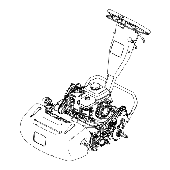
Chapter 4 Product Overview Grass basket Kickstand Handle Fuel tank Transport wheel axle Cutting unit G406958 3460-879 A Page 4–1 Product Overview... -
Page 16: Controls
Controls G406959 Throttle control Clutch bail Hour meter Cutting-unit-drive lever Lift-assist handle Parking-brake latch On/Off switch Service-brake lever Clutch Bail Use the clutch bail to engage or disengage the traction drive. • Engage the traction drive : Pull up and hold the bar to the handle. •... - Page 17 Clutch Bail (continued) G404693 Reel Speed Control Use the reel-speed-control knob to engage adjust the reel speed. • High reel speed: Rotate the knob so that the “H” on the knob is directed toward the front of the machine. • Low reel speed: Rotate the knob so that the “L”...
- Page 18 On/Off Switch • Start the engine : Push the upper part of the switch. • Shut off the engine : Push the lower part of the switch. G404698 Service-Brake Lever Pull the service-brake lever toward the handle to slow or stop the machine. G404699 Parking-Brake Latch •...
- Page 19 Cutting-Unit-Drive Lever Use the cutting-unit-drive lever to engage or disengage the cutting unit while the clutch bail is engaged. • Engage the cutting unit : Move the lever down. • Disengage the cutting unit : Move the lever G404701 Hour Meter The hour meter records the total running time of the engine to assist in scheduling regular maintenance.
-
Page 20: Engine Controls
Engine Controls G404703 Recoil-starter handle Choke lever Fuel-shutoff valve Choke Lever the choke before starting a NGAGE cold engine. the choke when the ISENGAGE engine is warm. G404704 Product Overview: Controls Page 4–6 3460-879 A... - Page 21 Engine Controls (continued) Fuel-Shutoff Valve Close the fuel-shutoff valve when the machine is not used for a few days, during transport to and from the job site, or when the machine is parked inside a building. Closed Open G404705 Recoil-Starter Handle Pull the recoil-starter handle to start the engine.
- Page 22 Kickstand (continued) CAUTION The machine is heavy and can cause back strain if lifted improperly. Put your foot pressure down on the kickstand and use only the lift-assist handle to raise the machine. Attempting to raise the machine onto the kickstand any other way can cause injury.
-
Page 23: Specifications
*Traction unit only. Refer to the cutting unit Operator’s Manual for the weight of each cutting unit. Attachments/Accessories A selection of Toro approved attachments and accessories is available for use with the machine to enhance and expand its capabilities. Contact your Authorized Service Dealer or authorized Toro distributor or go to www.Toro.com... -
Page 24: Chapter 5: Operation
Chapter 5 Operation Before Operation Before Operation Safety General Safety • Never allow children or untrained people to operate or service the machine. Local regulations may restrict the age of the operator. The owner is responsible for training all operators and mechanics. •... -
Page 25: Performing Daily Maintenance
Before Operation Safety (continued) • Keep the nozzle in contact with the rim of the fuel tank or container operating at all times until fueling is complete. Performing Daily Maintenance Before starting the machine each day, perform the Each Use/Daily procedures listed in the Maintenance Schedule. - Page 26 Fuel (continued) Filling the Fuel Tank 1. Clean around the fuel-tank cap and remove the cap from the tank. G404710 2. Add the recommended fuel to the full level (i.e., to the bottom of the fuel gauge ) in the fuel tank.
-
Page 27: Adjusting The Clip Rate
Adjusting the Clip Rate Determine the appropriate clip rate per the following table: Clip Rate Reel Speed Pulley Cutting Unit Position 8-blade 11-blade 14-blade 7.3 mm (0.286 inch) 5.3 mm (0.208 inch) 4.2 mm (0.164 inch) High 6.1 mm (0.241 inch) 4.4 mm (0.175 inch) 3.5 mm (0.137 inch) -
Page 28: During Operation
During Operation During Operation Safety General Safety • The owner/operator can prevent and is responsible for accidents that may cause personal injury or property damage. • Wear appropriate clothing, including eye protection; long pants; substantial, slip-resistant footwear; and hearing protection. Tie back long hair and do not wear loose clothing or loose jewelry. -
Page 29: Starting The Engine
– Before leaving the operating position • Use only accessories and attachments approved by The Toro® Company. Slope Safety • Slopes are a major factor related to loss of control and rollover accidents, which can result in severe injury or death. -
Page 30: Mowing Overview
Starting the Engine (continued) 2. Ensure that the fuel-shutoff valve is open 3. Move the On/Off switch to the O position. 4. Use the throttle control to increase the engine speed. 5. Move the choke lever halfway between the C and R positions when starting a HOKE... -
Page 31: Shutting Off The Engine
Mowing Overview (continued) • Turn the machine off the green by raising the cutting reel (pushing the handle down) and performing a tear-shaped turn on the traction drum. • Mow at a normal walking pace. Fast speeds saves little time and results in an inferior mowing job. -
Page 32: After Operation
After Operation After Operation Safety General Safety • Shut off the machine, remove the key (if equipped), and wait for all movement to stop before you leave the operator’s position. Allow the machine to cool before adjusting, servicing, cleaning, or storing it. •... -
Page 33: Disengaging The Transmission
Installing the Transport Wheels You can purchase an optional Transport Wheel Kit (Model 04123); contact your authorized Toro distributor. 1. Ensure that the tires are inflated to 83 to 103 kPa (12 to 15 psi). 2. Move the kickstand to the T position. -
Page 34: Transporting The Machine Using Transport Wheels
Installing the Transport Wheels (continued) 3. Slide a wheel onto an axle 4. Pivot the wheel-locking clip away from center of the wheel, allowing it to slide farther onto the axle. 5. Rotate the wheel back and forth until it slides completely onto the axle and the locking clip is secured in the groove on the axle shaft. - Page 35 3460-879A Page 5–12 Operation: Transporting the Machine...
-
Page 36: Hauling The Machine
Note: You can use the Toro Trans Pro trailer to transport the machine. For instructions on loading the trailer, refer to your trailer Operator’s Manual. 1. Carefully drive the machine onto the trailer. -
Page 37: Chapter 6: Maintenance
Chapter 6 Maintenance WARNING Failure to properly maintain the machine could result in premature failure of machine systems, causing possible harm to you or bystanders. Keep the machine well maintained and in good working order as indicated in these instructions. Note: Determine the left and right sides of the machine from the normal operating position. -
Page 38: Maintenance Safety
• To ensure safe, optimal performance of the machine, use only genuine Toro replacement parts. Replacement parts made by other manufacturers could be dangerous, and such use could void the product warranty. • If major repairs are ever needed or if assistance is desired, contact an authorized Toro distributor. -
Page 39: Recommended Maintenance Schedule
Recommended Maintenance Schedule Maintenance Description Maintenance Procedure Part No. Service Interval After the first 20 Change the engine oil. 38280 Bottle of oil hours Check the engine-oil level. Before each use or daily Inspect the air-filter elements. Every 50 hours Clean the air-filter elements. -
Page 40: Daily Maintenance Checklist
Daily Maintenance Checklist Duplicate this page for routine use. Maintenance For the week of: Check Item Mon. Tues. Wed. Thurs. Fri. Sat. Sun. Check the brake- lock-lever operation. Check the fuel level. Check the engine- oil level. Check the air filter. Clean the engine cooling fins. -
Page 41: Pre-Maintenance Procedures
Pre-Maintenance Procedures Preparing the Machine for Maintenance WARNING While you are maintaining or adjusting the machine, someone could start the engine. Accidentally starting the engine could seriously injure you or other bystanders. Release the clutch bail, engage the parking brake, and pull the wire off the spark plug before you do any maintenance. -
Page 42: Engine Oil Specifications
Engine Oil Specifications Crankcase capacity: 0.56 L (19 fl oz) Oil type: API classification SJ or later. Oil viscosity: Select the oil viscosity according to ambient temperature in the table below. Note: Multi-grade oils (5W-30 and 10W-30) increase oil consumption. Check the engine-oil level more frequently when you use these oils. -
Page 43: Changing The Engine Oil
Checking the Engine-Oil Level (continued) 7. If the engine-oil level is incorrect, add or drain oil to correct the level. Note: If the oil level is near or below the lower level mark on the dipstick, add only enough of the specified oil to raise the level to the upper limit mark (bottom edge of the oil fill hole) Changing the Engine Oil... - Page 44 Servicing the Air Cleaner (continued) 1. Shut off the engine and wait for all moving parts to stop. 2. Remove the wingnut securing the air- cleaner cover 3. Remove the air-cleaner cover. G404895 IMPORTANT Ensure that no dirt or debris from the air-cleaner cover fall into the base. 4.
-
Page 45: Servicing The Spark Plug
Servicing the Air Cleaner (continued) 8. Clean the foam element in warm, soapy water or in a nonflammable solvent. IMPORTANT Do not use gasoline to clean the foam element because it could create a risk of fire or explosion. 9. Rinse and dry the foam element thoroughly. 10. -
Page 46: Controls Maintenance
Servicing the Spark Plug (continued) 6. Tighten the spark plug an additional 1/2 turn if it is new; otherwise, tighten it an additional 1/8 to 1/4 turn. IMPORTANT A loose spark plug can become very hot and can damage the engine; overtightening a spark plug may damage the threads in the cylinder head. - Page 47 Adjusting the Traction Cable (continued) 2. Loosen the jam nuts and adjust the traction cable so that a 1.1 mm (0.045 inch) is between the friction disc and the pressure plate G404911...
-
Page 48: Adjusting The Service/Parking Brake
Adjusting the Service/Parking Brake Adjust the service/parking brake if it slips during operation. 1. Disengage the parking brake. 2. Measure the free play at the end of the parking-brake handle The handle free play should be between 12.7 to 25.4 mm (0.50 to 1 inch) . -
Page 49: Adjusting The Throttle Cable
Adjusting the Reel-Control Cable (continued) 1. Move the reel-speed-control knob to the high- reel-speed position. 2. Loosen the rear jam nut and tighten the front jam nut G404914 Adjusting the Throttle Cable Adjusting the Low-Idle Engine Speed 1. Park the machine on a level surface and engage the parking brake. 2. -
Page 50: Cutting Unit Maintenance
Adjusting the Throttle Cable (continued) Adjusting the High-Idle Engine Speed 1. Park the machine on a level surface and engage the parking brake. Note: Ensure that the engine is at a normal operating temperature before you adjust the throttle cable. 2. - Page 51 Installing the Cutting Unit (continued) 2. Remove the hardware that secures the reel- drive assembly to the side plate. 3. Remove the reel-drive assembly, flat washers, spring washers, and spacers from the side plate. 4. Align the cutting unit to the frame. G404920 5.
- Page 52 Installing the Cutting Unit (continued) 3. Use 4 socket-head screws to secure the cutting unit to the frame. 4. Slide the cutting-unit-drive coupler onto the transmission driveshaft. The coupler should slide onto the transmission driveshaft without resistance. If there is resistance, ensure that the reel driveshaft and the transmission driveshaft are aligned 5.
-
Page 53: Removing The Cutting Unit
Removing the Cutting Unit Removing the Cutting Unit Model 04820 Only 1. Move the kickstand to the C position. UTTING ERVICE 2. Remove the grass basket (if equipped). 3. Remove the reel-drive assembly from the cutting unit and retain the hardware. G404926 4. -
Page 54: Backlapping Information
Access Backlap Kit (Model 139-4342) Models 04820, 04830, and 04840 Backlap Kit (Model 04800) Models 04830 and 04840 Refer to the operating instructions in the specific kit Installation Instructions. Contact your authorized Toro distributor to acquire one of these kits. -
Page 55: Chapter 7: Storage
3. Check and tighten all bolts, nuts, and screws. Repair or replace any part that is worn or damaged. 4. Paint all scratched or bare metal surfaces. Paint is available from your authorized Toro distributor. 5. Store the machine in a clean, dry garage or storage area. Cover the machine to protect it and keep it clean. -
Page 56: The Toro Warranty
Conditions and Products Covered Toro. Toro will make the final decision whether to repair any existing part or assembly or replace it. Toro may use remanufactured parts for warranty repairs. -
Page 57: California Proposition 65 Warning Information
Toro has chosen to provide consumers with as much information as possible so that they can make informed decisions about the products they buy and use. Toro provides warnings in certain cases based on its knowledge of the presence of one or more listed chemicals without evaluating the level of exposure, as not all the listed chemicals provide exposure limit requirements. - Page 58 Notes:...
- Page 59 Notes:...
Need help?
Do you have a question about the Greensmaster 1018 and is the answer not in the manual?
Questions and answers