Table of Contents
Advertisement
Quick Links
Advertisement
Table of Contents

Related Manuals for Lenovo 10TX


Summary of Contents for Lenovo 10TX
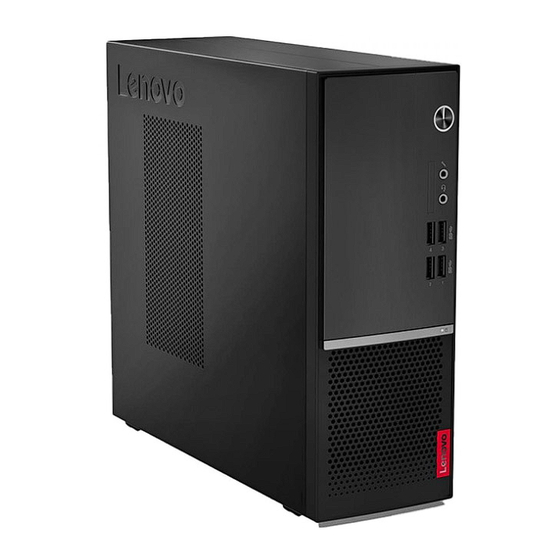
- Page 1 Computador Lenovo V50S Projetado para reduzir o consumo de energia e proporcionar uma operação silenciosa, o PC Lenovo V50s permite reduzir os custos de energia e barulho ‐ é certificado para baixo ruído e eficiência energética. bztech.com.br...
- Page 2 V530S-07ICB User Guide and Hardware Maintenance Manual Energy Star Machine Types: 10TX, 10TY, 10XV, and 10XW...
- Page 3 Important Product Information Guide and Appendix A “Notices” on page 47. Second Edition (May 2019) © Copyright Lenovo 2019. LIMITED AND RESTRICTED RIGHTS NOTICE: If data or software is delivered pursuant to a General Services Administration “GSA” contract, use, reproduction, or disclosure is subject to restrictions set forth in Contract No. GS-...
-
Page 4: Table Of Contents
Replacing the storage drive ..Appendix B. Trademarks ..49 Replacing the card reader ... © Copyright Lenovo 2019... - Page 5 V530S-07ICB User Guide and Hardware Maintenance Manual...
-
Page 6: Chapter 1. Overview
USB 3.1 Gen 1 connectors (2) USB 3.1 Gen 2 connectors (2) Optical drive eject/close button Used to eject the tray of the optical drive. After you insert a disc into the tray, press the eject/close button to close the tray. © Copyright Lenovo 2019... - Page 7 Optical drive activity indicator This indicator is on when the optical drive is in use. Card reader slot Used to read data from a supported memory card. Storage drive activity indicator This indicator is on when the storage drive is in use. Power indicator This indicator is on when the computer is on.
-
Page 8: Rear View
Rear view Note: Your computer model might look slightly different from the illustration. Figure 2. Rear view Audio line-out connector HDMI 1.4 out connector ® DisplayPort 1.2 out connector VGA-out connector USB 2.0 connectors (2) USB 3.1 Gen 1 connectors (2) Power cord connector Serial connector Ethernet connector... - Page 9 Note: If your computer has both an audio line-out connector and a headset or headphone connector, always use the headset or headphone connector for earphones, headphones, or a headset. The headphone connector does not support headset microphones. HDMI 1.4 out connector Used to send audio and video signals from the computer to another audio or video device, such as a high- performance monitor.
-
Page 10: System Board
To improve the operating performance of the computer, you can connect PCI-Express cards into this area. Depending on the computer model, the connectors in this area vary. System board Note: See “Front view” and “Rear view” for additional component descriptions. Figure 3. -
Page 11: Machine Type And Model Label
Machine type and model label The machine type and model label identifies the computer. When you contact Lenovo for help, the machine type and model information helps support technicians to identify the computer and provide faster service. The machine type and model label is attached on the computer as shown. -
Page 12: Chapter 2. Specifications
• USB connectors Expansion • Card reader • Memory slots • Optical drive (optional) • PCI Express x1 card slot • PCI Express x16 graphics card slot • Storage drive bay Network features • Ethernet LAN © Copyright Lenovo 2019... - Page 13 • Wireless LAN (optional) • Bluetooth (optional) Physical dimensions • Width: 100.0 mm (3.9 inches) • Height: 274.8 mm (10.8 inches) • Depth: 304.4 mm (12.0 inches) Weight (without the package) Maximum configuration as shipped: 4.2 kg (9.3 lb) Statement on USB transfer rate Depending on many factors such as the processing capability of the host and peripheral devices, file attributes, and other factors related to system configuration and operating environments, the actual transfer rate using the various USB connectors on this device will vary and will be slower than the data rate listed...
-
Page 14: Chapter 3. Computer Locks
Depending on the type selected, the cable lock can be operated with a key or a combination. The cable lock also locks the buttons used to open the computer cover. This is the same type of lock used with many notebook computers. You can order such a cable lock directly from Lenovo by searching for Kensington at: http://www.lenovo.com/support... - Page 15 Figure 6. Attaching a Kensington-style cable lock Attaching a smart cable clip A smart cable clip can be used to secure devices, such as the keyboard and the mouse, by locking the device cables to the computer. The smart cable clip connects to the cable-lock slots on the rear of the computer.
-
Page 16: Chapter 4. Replacing Hardware
• When installing or replacing an option, use the appropriate instructions explained in this manual along with the instructions that come with the option. • In most areas of the world, Lenovo requires the return of defective CRUs. Information about this will come with the CRU or will come a few days after the CRU arrives. -
Page 17: Locating Frus (Including Crus)
Locating FRUs (including CRUs) Notes: • Some of the following components are optional. • To replace a component that is not in the list below, contact a Lenovo service technician. For a list of Lenovo Support phone numbers, go to: http://www.lenovo.com/support/phone... - Page 18 Figure 8. Locating FRUs (including CRUs) Self-service CRUs Optional-service CRUs Non-CRUs Computer cover Coin-cell battery System board Memory module Power supply assembly Microprocessor Storage drive bracket Wi-Fi card shield M.2 solid-state drive Wi-Fi card Storage drive (a 2.5-inch or 3.5- Storage drive cable inch storage drive) Optical drive bracket...
-
Page 19: Removing The Computer Cover
Self-service CRUs Optional-service CRUs Non-CRUs Keyboard Storage drive activity indicator Mouse Wi-Fi antennas (2) Power cord Thermal sensor PCI Express card Chassis Rear Wi-Fi antenna cover Heat sink and fan assembly Removing the computer cover Attention: Do not open your computer or attempt any repairs before reading the Important Product Information Guide. -
Page 20: Replacing The Optical Drive
Figure 10. Removing the front bezel Figure 11. Installing the front bezel 3. Complete the replacement. See “Completing the parts replacement” on page 45. Replacing the optical drive Attention: Do not open your computer or attempt any repairs before reading the Important Product Information Guide. - Page 21 Figure 12. Removing the optical drive Figure 13. Removing the optical drive bracket Figure 14. Installing the optical drive bracket V530S-07ICB User Guide and Hardware Maintenance Manual...
-
Page 22: Replacing The Storage Drive
Figure 15. Installing the optical drive 5. Connect the signal cable and the power cable to the new optical drive. 6. Reinstall the removed parts. To complete the replacement, see “Completing the parts replacement” on page 45. Replacing the storage drive Attention: Do not open your computer or attempt any repairs before reading the Important Product Information Guide. - Page 23 Figure 17. Removing the 3.5-inch storage drive Figure 18. Installing the 3.5-inch storage drive V530S-07ICB User Guide and Hardware Maintenance Manual...
- Page 24 Figure 19. Installing the storage drive bracket • 2.5-inch storage drive Figure 20. Removing the storage drive bracket Chapter 4 Replacing hardware...
- Page 25 Figure 21. Removing the 2.5-inch storage drive Figure 22. Installing the 2.5-inch storage drive V530S-07ICB User Guide and Hardware Maintenance Manual...
-
Page 26: Replacing The Card Reader
Figure 23. Installing the storage drive bracket 6. Connect the signal cable and the power cable to the new storage drive. 7. Reinstall the removed parts. To complete the replacement, see “Completing the parts replacement” on page 45. Replacing the card reader Attention: Do not open your computer or attempt any repairs before reading the Important Product Information Guide. - Page 27 Figure 25. Removing the card reader Figure 26. Installing the card reader Figure 27. Installing the card reader bracket 7. Connect the new card reader cable to the system board. V530S-07ICB User Guide and Hardware Maintenance Manual...
-
Page 28: Replacing The Storage Drive Activity Indicator
8. Reinstall the removed parts. To complete the replacement, see “Completing the parts replacement” on page 45. Replacing the storage drive activity indicator Attention: Do not open your computer or attempt any repairs before reading the Important Product Information Guide. 1. -
Page 29: Replacing The Thermal Sensor
2. Remove the front bezel. See “Replacing the front bezel” on page 14. 3. Remove the optical drive. See “Replacing the optical drive” on page 15. 4. Remove the storage drive bracket. See “Replacing the storage drive” on page 17. 5. -
Page 30: Replacing The Wi-Fi Card
3. Remove the optical drive. See “Replacing the optical drive” on page 15. 4. Remove the storage drive bracket. See “Replacing the storage drive” on page 17. 5. Disconnect the thermal sensor cable from the system board. 6. Replace the thermal sensor. Figure 32. - Page 31 3. Remove the optical drive. See “Replacing the optical drive” on page 15. 4. Remove the storage drive bracket. See “Replacing the storage drive” on page 17. 5. Replace the Wi-Fi card. Figure 34. Removing the Wi-Fi card shield Figure 35. Disconnecting the Wi-Fi antenna cables Figure 36.
-
Page 32: Replacing The Wi-Fi Antennas
Figure 37. Installing the Wi-Fi card Figure 38. Connecting the Wi-Fi antenna cables Figure 39. Installing the Wi-Fi card shield 6. Reinstall the removed parts. To complete the replacement, see “Completing the parts replacement” on page 45. Replacing the Wi-Fi antennas Attention: Do not open your computer or attempt any repairs before reading the Important Product Information Guide. - Page 33 • Front Wi-Fi antenna Figure 40. Removing the front Wi-Fi antenna Figure 41. Installing the front Wi-Fi antenna • Rear Wi-Fi antenna V530S-07ICB User Guide and Hardware Maintenance Manual...
- Page 34 Figure 42. Removing the rear Wi-Fi antenna cover Figure 43. Removing the rear Wi-Fi antenna Figure 44. Installing the rear Wi-Fi antenna Chapter 4 Replacing hardware...
-
Page 35: Replacing The M.2 Solid-State Drive
Figure 45. Installing the rear Wi-Fi antenna cover 7. Connect the new Wi-Fi antenna cables to the Wi-Fi card. 8. Reinstall the removed parts. To complete the replacement, see “Completing the parts replacement” on page 45. Replacing the M.2 solid-state drive Attention: Do not open your computer or attempt any repairs before reading the Important Product Information Guide. - Page 36 Figure 47. Removing the M.2 solid-state drive Figure 48. Installing the M.2 solid-state drive Figure 49. Installing the screw • Type 2 Figure 50. Pulling out the stopper Chapter 4 Replacing hardware...
-
Page 37: Replacing The Coin-Cell Battery
Figure 51. Removing the M.2 solid-state drive Figure 52. Installing the M.2 solid-state drive Figure 53. Inserting the stopper 6. Reinstall the removed parts. To complete the replacement, see “Completing the parts replacement” on page 45. Replacing the coin-cell battery Attention: Do not open your computer or attempt any repairs before reading the Important Product Information Guide. - Page 38 5. Replace the coin-cell battery. Figure 54. Disengaging the latch Figure 55. Removing the coin-cell battery Figure 56. Installing the coin-cell battery Chapter 4 Replacing hardware...
-
Page 39: Replacing A Memory Module
Figure 57. Securing the coin-cell battery with the latch 6. Reinstall the removed parts. To complete the replacement, see “Completing the parts replacement” on page 45. Replacing a memory module Attention: Do not open your computer or attempt any repairs before reading the Important Product Information Guide. - Page 40 Figure 58. Disengaging the latches Figure 59. Removing a memory module Figure 60. Installing a memory module Chapter 4 Replacing hardware...
-
Page 41: Replacing The Heat Sink And Fan Assembly
Figure 61. Securing a memory module with the latches 6. Reinstall the removed parts. To complete the replacement, see “Completing the parts replacement” on page 45. Replacing the heat sink and fan assembly Attention: Do not open your computer or attempt any repairs before reading the Important Product Information Guide. -
Page 42: Replacing The Microprocessor
Figure 63. Installing the heat sink and fan assembly 4. Connect the new microprocessor fan cable to the system board. 5. Reinstall the removed parts. To complete the replacement, see “Completing the parts replacement” on page 45. Replacing the microprocessor Attention: Do not open your computer or attempt any repairs before reading the Important Product Information Guide. - Page 43 Figure 64. Releasing the handle Figure 65. Opening the retainer Figure 66. Removing the microprocessor V530S-07ICB User Guide and Hardware Maintenance Manual...
- Page 44 Figure 67. Installing the microprocessor Chapter 4 Replacing hardware...
- Page 45 Figure 68. Closing the retainer Figure 69. Securing the retainer with the handle 5. Route all the cables that you disconnected from the system board, and then reconnect the cables to the system board. 6. Reinstall the removed parts. To complete the replacement, see “Completing the parts replacement” on page 45.
-
Page 46: Replacing A Pci Express Card
Replacing a PCI Express card Attention: Do not open your computer or attempt any repairs before reading the Important Product Information Guide. 1. Remove the computer cover. See “Removing the computer cover” on page 14. 2. Replace a PCI Express card. Figure 70. -
Page 47: Replacing The Power Supply Assembly
Figure 71. Installing a PCI Express card Figure 72. Securing a PCI Express card with the latch 3. Reinstall the removed parts. To complete the replacement, see “Completing the parts replacement” on page 45. Replacing the power supply assembly Attention: Do not open your computer or attempt any repairs before reading the Important Product Information Guide. - Page 48 Hazardous moving parts. Keep fingers and other body parts away. CAUTION: Never remove the cover on a power supply or any part that has the following label attached. Hazardous voltage, current, and energy levels are present inside any component that has this label attached.
-
Page 49: Replacing The System Board
Figure 74. Installing the power supply assembly 7. Connect the new power supply assembly cables to the system board. 8. Reinstall the removed parts. To complete the replacement, see “Completing the parts replacement” on page 45. Replacing the system board Attention: Do not open your computer or attempt any repairs before reading the Important Product Information Guide. -
Page 50: Completing The Parts Replacement
14. Route and connect all the cables to the new system board. 15. Reinstall the removed parts. To complete the replacement, see “Completing the parts replacement” on page 45. Completing the parts replacement After completing the installation or replacement for all parts, reinstall the computer cover and reconnect the cables. - Page 51 V530S-07ICB User Guide and Hardware Maintenance Manual...
-
Page 52: Appendix A. Notices
Lenovo representative for information on the products and services currently available in your area. Any reference to a Lenovo product, program, or service is not intended to state or imply that only that Lenovo product, program, or service may be used. Any functionally equivalent product, program, or service that does not infringe any Lenovo intellectual property right may be used instead. - Page 53 V530S-07ICB User Guide and Hardware Maintenance Manual...
-
Page 54: Appendix B. Trademarks
Video Electronics Standards Association. The terms HDMI and HDMI High-Definition Multimedia Interface are trademarks or registered trademarks of HDMI Licensing LLC in the United States and other countries. All other trademarks are the property of their respective owners. © 2019 Lenovo. © Copyright Lenovo 2019... - Page 55 V530S-07ICB User Guide and Hardware Maintenance Manual...
- Page 58 Computador Lenovo V530S SFF Responsivo, confiável e compacto, o desktop V530s SFF é a escolha perfeita para negócios cotidianos. Equipado com os mais recentes processadores Intel Core, memória DDR4 e SSD PCIe de alta velocidade, este desktop lida com multitarefas...
Need help?
Do you have a question about the 10TX and is the answer not in the manual?
Questions and answers