Table of Contents
Advertisement
Quick Links
Advertisement
Table of Contents

Related Manuals for Honeywell EC350


Summary of Contents for Honeywell EC350
- Page 1 EC350 EC350 User Manual FD-583 | V1.6 | 2024 Honeywell Process Solutions Mercury Instruments, 2101 Citywest Boulevard Houston, TX 77042 USA 855 251-7065 – United States & Canada 302 669-4253 – Outside the United States https://process.honeywell.com...
- Page 2 Honeywell Process Solutions.
- Page 3 This document is for operators and technicians working in the natural gas industry. This document provides an overview of EC350 and instructions to install EC350 on any meter equipped with an instrument drive capability (common to diaphragm and turbine meters) using a Universal Mounting Bracket (UMB) or a rotary mount.
- Page 4 The following table lists some special terms that are used across this document and provides their definitions. Term Definition Meter gasket It is used as an environmental seal for mounting EC350 on a meter. Opto-isolators Devices that prevent unwanted current flow or possible damage from high voltage or/and from external devices connected to the instrument.
-
Page 5: Table Of Contents
3.1 EC350 contents verification 3.2 Overview of installation 3.3 Model number interpretation 3.4 Prerequisites 3.5 Installing EC350 on conventional diaphragm, rotary or turbine gas meters 3.5.1 Installing the index slide and label 3.5.1.1 Next steps 3.5.2 Changing the drive rotation 3.5.3 Mounting EC350 on the meter... - Page 6 3.6.4 Installing EC350 on rotary mounts 3.7 Power Supply Options 3.7.1 External Power Supply 3.7.2 Battery Powered 3.8 General Wiring connections 3.8.1 Pulse output communication 3.8.2 Pulse output specification 3.8.3 Pulse outputs via the case connector option 3.9 Installation Drawings 4 Securing the device 4.1 Case...
- Page 7 5.3.3.1 Entering Pushbutton Proving mode 5.3.4 Volume per proving output pulse 5.4 Alarms 5.5 Logging 5.5.1 Audit Trail Logging Configuration 5.5.2 Reading Audit Trail from the EC350 5.5.2.1 Displaying/Viewing Audit Trail reports 5.5.3 Event logger 5.5.3.1 Supported Event Codes 5.5.3.2 Clearing Event Log 5.5.4 Log record integrity verification...
- Page 8 R610 6.3.1 About MasterLink Software Application R610 6.3.2 Connecting the IrDA communication USB dongle to the computer 6.3.3 Connecting the IrDA communication USB dongle to EC350 166 6.3.4 Signing on to the EC350 6.3.5 Updating EC350 firmware 6.3.5.1 Application Firmware 6.3.5.2 Key File...
- Page 9 7.2.2.2 Set a call out stop time 7.3 Modbus Communication 8 Maintenance 8.1 Temperature Probe Measurement Kits 8.2 Transducer Replacement Kits 8.3 Redundant Uncorrected Switch 8.4 Metrological Sealing Cover (MC) 8.5 Removing and Re-Installing Modem Mounting Plate 8.6 Replacing the Battery Pack 8.6.1 Replacing the battery in a hazardous DIV-1/ZONE-0 environment 8.6.2 Replacing the battery in a non-hazardous environment...
-
Page 10: About Ec350
1 About EC350 This section provides information about the main interfaces of EC350 - LCD, Keypad, and External connections. It also lists the safety instructions that must be followed while installing and commissioning EC350. Safety instructions Theory of Operation Main interfaces of EC350... -
Page 11: Ec350 Specifications
1 About EC350 1.1 EC350 specifications 1.1 EC350 specifications This section provides the specifications and certifications for EC350. Certifications Power Environmental Temperature measurement Pressure measurement API 21.1 compliance 1.1.1 Certifications Electrostatic Discharge Immunity Test (EN61000-4-2) Radiated, Radio-Frequency Electromagnetic Field Immunity Test (EN61000-4-3) -
Page 12: Environmental
Operating Temperature Range: -40 °F to +149 °F (-40 °C to +65 °C). If you are using an EC350 device with a modem, then it is recommended to consider the operational temperature range of the modem. The temperature system will continue providing accurate measurements even if the modem is unable to operate because of environmental conditions. -
Page 13: Pressure Measurement
1 About EC350 1.1 EC350 specifications 1.1.5 Pressure measurement EC350 have 2 pressure sensor slots By default, Pressure 1 is used for volume correction. Pressure 1 is enabled or disabled by using i1052. By default, Pressure 2 is used as a pressure monitor . Pressure 2 is enabled or disabled by using i1053. -
Page 14: Safety Instructions
EC350 is approved for use in hazardous areas (Class I Division 1 or Class I Division 2). Different versions of EC350 are available depending on the operating conditions. The permitted operating conditions are marked on each EC350. -
Page 15: Things To Remember
Zone 0 location. In addition, the equipment shall only be cleaned with a damp cloth. EC350 shall be installed as per DWG 40-6061, and ERX 350 shall be installed as per DWG 40-6156. Battery packs 40-6050, 40-6054 and 40-6064 shall only be changed in a non-hazardous area. - Page 16 Hazardous areas. The battery pack and the external power supply shall not be connected simultaneously. When EC350 is used with Itron 100G, Itron 500G, or Aclara 3322, the assembly shall be restricted to Class I, Division 1, Group D environment only.
-
Page 17: Service, Maintenance, And Troubleshooting Ec350
Installation and commission EC350 in hazardous areas: EC350 must be installed and commissioned only by specially trained and qualified staff. The device is designed in accordance with the IP 65 degree of protection as per EN 60529. The installation of the intrinsically safe circuits must comply with the applicable local laws or regulations. - Page 18 1 About EC350 1.2 Safety instructions Note: This equipment has been tested and found to comply with the limits for a Class A digital device, pursuant to part 15 of the FCC Rules. These limits are designed to provide reasonable protection against harmful interference in a residential installation.
-
Page 19: Theory Of Operation
1 About EC350 1.3 Theory of Operation 1.3 Theory of Operation Correction Factors to Metered Volume Pressure Factor Fp Temperature Factor Ft Supercompressibiity Factor Fpv 1.3.1 Correction Factors to Metered Volume Ideal or perfect gases follow the relationship of Boyle’s Law for pressure effect and Charles’ Law for temperature effect, which can be stated: The volume of any definite weight of a perfect gas varies inversely with change in absolute pressure and directly with change in absolute temperature. -
Page 20: Pressure Factor Fp
“supercompressibility” is used for this deviation. It is small at very low pressure, but becomes substantial as the pressure increases. The EC350 automatically applies the supercompressibility factor and therefore the equation for total volume correction that the EC350 applies to metered volume, is expressed as: Where: Vb = gas volume (cu. - Page 21 1 About EC350 1.3 Theory of Operation The EC350 automatically squares the supercompressibility factor displayed, which is based on the pressure and temperature sensed at the meter. The resulting volume readout is corrected for pressure, temperature, and supercompressibility. Honeywell 2024...
-
Page 22: Main Interfaces Of Ec350
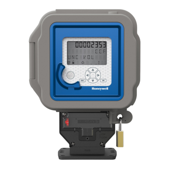
External connections 1.4.1 LCD EC350 provides a ten character, configurable, alphanumeric LCD display with icons to display the status information and alarm conditions. The LCD display can be configured to on or off at different times of day. During normal operation (Correction mode), the corrected volume is displayed on the LCD. Following is an LCD display illustration, showing all segments ON. -
Page 23: Keypad
Use this key to display the Home screen, cancel an entry, or go back to the previous menu. To conserve battery power, after each processing cycle the EC350 keypad is locked, if there is no input received within the time out period (1 to 10 minutes). -
Page 24: External Connections
1.4.3 External Connections The external connections from EC350 are: Pulse outputs Serial port Alarm outputs External supply voltage (TB1) Battery pack (P5) The figure below illustrates the purpose of different jumpers and other connections on an EC350 IO board: Honeywell 2024... -
Page 25: Security Guidelines
2 Security Guidelines This section provides security guidelines for EC350 device. -
Page 26: Device Security Recommendations
Use an earth connection interlock to prevent loading from starting without the driver physically present. For more secure access use the password encryption functionality by enabling item 1698 through the MasterLink desktop application. By default, the password encryption functionality (Item 1698) is disabled. Honeywell 2024... -
Page 27: Implementing Stringent Password Guidelines
For more secure access, use password encryption functionality (i.e., encrypted sign-on) by enabling item number 1698 in the MasterLink application. If the password encryption is enabled then the password used to access the EC350 device will be in encrypted form. By default, this functionality is disabled in the MasterLink application. -
Page 28: How To Report A Security Vulnerability
Honeywell reviews all reports about vulnerabilities relating to Honeywell products and services. You can find further information about the Honeywell Security Policy at: www.honeywell.com/product-security If you would like to report a possible vulnerability in a Honeywell product, follow the instructions on the Honeywell website at: www.honeywell.com/product-security You can find information about current malware threats at: https://process.honeywell.com... -
Page 29: Preventing Unauthorized External Access Using A Firewall
“external” central billing or control system and the “internal” network of the gas metering systems. Furthermore, EC350 device should only be installed in the gas metering system, where access control is guaranteed, i.e., protective action is taken to prevent unauthorized persons gaining access to the device. -
Page 30: Ec350 Installation
3 EC350 installation This chapter deals with the installation of EC350 on conventional gas meters (such as rotary, diaphragm, and turbine). This chapter also provides procedures for installing and replacing the battery and output wire connections to obtain pulse output from EC350. -
Page 31: Ec350 Contents Verification
3 EC350 installation 3.1 EC350 contents verification 3.1 EC350 contents verification The following components are installed and connected inside EC350 when shipped. Pressure transducers (upto 2 transducers, if ordered) Temperature probe (if ordered) Volume input method (if ordered) Telemetry (if ordered) After you receive EC350: Remove the contents from the box and from the mounting kit bag. -
Page 32: Overview Of Installation
“Model number interpretation ”, to familiarize yourself with the EC350 model you have selected. Based on the mounting selected, refer to one of the following two methods for installing EC350 on a meter. Installing EC350 on conventional diaphragm, rotary or turbine gas meters. The following image illustrates with a UMB. - Page 33 3 EC350 installation 3.2 Overview of installation Honeywell 2024...
-
Page 34: Model Number Interpretation
3 EC350 installation 3.3 Model number interpretation 3.3 Model number interpretation EC350 is available in different models. Refer to the Model Selection Guide (MSG), available from your Mercury sales representative, for details. 3.4 Prerequisites Ensure that the following components are installed and connected inside EC350, before installing EC350 on meters. -
Page 35: Installing Ec350 On Conventional Diaphragm, Rotary Or Turbine Gas Meters
3.5 Installing EC350 on conventional diaphragm, rotary or turbine gas meters 3.5 Installing EC350 on conventional diaphragm, rotary or turbine gas meters This section describes the procedures to install EC350 on conventional diaphragm, rotary or turbine gas meters, equipped with instrument drive capability. Installing the index slide and label... -
Page 36: Next Steps
3 EC350 installation 3.5 Installing EC350 on conventional diaphragm, rotary or turbine gas meters The following image illustrates the labels applied to the UMB, slides, and rivets. 3.5.1.1 Next steps Verify if the digital index reading rotates in the proper direction. If not, perform the tasks described in the following section, “... -
Page 37: Changing The Drive Rotation
The bevel-gear Thimble assembly or the Thimble gear assembly in the UMB permits either clockwise (CW) or counterclockwise (CCW) rotation. Before installing EC350, note whether the output shaft of the meter rotates CW or CCW. You can change the driver rotation by positioning the Thimble gear assembly of EC350 to match the meter rotation. -
Page 38: Mounting Ec350 On The Meter
3.5 Installing EC350 on conventional diaphragm, rotary or turbine gas meters 3.5.3 Mounting EC350 on the meter Ensure that you have the right mounting kit. Refer to the MSG or the image provided along with EC350 to ensure it is the right mounting kit. -
Page 39: Connecting A Pressure Line To Ec350
To avoid explosion, it is extremely important to ensure the pressure transducer is capable of handling the pressure in the gas line. Check item entry 137 (user units) or item entry 25(PSI) on the EC350 for maximum pressure transducer information before applying live gas pressure to the EC350. Honeywell... -
Page 40: Installing Ec350 On A Rotary Mount
Connecting a pressure line to the EC350 Installing EC350 on rotary mounts 3.6.1 Selecting the mounting orientation EC350 supports four orientations for instruments and mounting plates. The EC350 can be rotated about 90 degrees increments based on your meter configuration. To select the mounting orientation: Loosen and remove the four mounting screws holding the mounting plate. -
Page 41: Installing The Temperature Probe
The temperature probe is held in place with a rubber gland in the mounting plate. Push the probe into EC350 until the mark is one inch from the mounting plate, as illustrated in the following image. The one inch additional length ensures that the probe bottoms out at the end of the thermowell. -
Page 42: Connecting A Pressure Line To The Ec350
3 EC350 installation 3.6 Installing EC350 on a rotary mount 3.6.3 Connecting a pressure line to the EC350 Use a pressure connection kit and connect the pressure line to the ¼ inch NPT fitting. The following images illustrates a pressure transducer connected to a pressure line using the pressure connection kit. -
Page 43: Installing Ec350 On Rotary Mounts
3.6 Installing EC350 on a rotary mount 3.6.4 Installing EC350 on rotary mounts This section describes the various types of rotary meter mounting kits. The following table illustrates the mounting of EC350 on each type of rotary mounts. Rotary meter Rotary mount illustration... - Page 44 3 EC350 installation 3.6 Installing EC350 on a rotary mount Rotary meter Rotary mount illustration Part mounting kit Number LMMA 1.5m to 22-2089- 5m and 23m to 102m mounting kit with Tamperproof screw. LMMA 7m to 22-2090 16m mounting kit with snap seals.
- Page 45 3 EC350 installation 3.6 Installing EC350 on a rotary mount Rotary meter Rotary mount illustration Part mounting kit Number LMMA 7m to 22-2090- 16m mounting kit with Tamperproof screw. Romet 22-2104 RM1000 to RM5000 mounting kit with snap seals. Romet...
- Page 46 3 EC350 installation 3.6 Installing EC350 on a rotary mount Rotary meter Rotary mount illustration Part mounting kit Number Romet 22-2104- RM1000 to RM5000 mounting kit with Tamperproof screw. Romet 7000 to 22-2105 23000 mounting kit with snap seals. Romet 7000 to...
- Page 47 3 EC350 installation 3.6 Installing EC350 on a rotary mount Rotary meter Rotary mount illustration Part mounting kit Number Romet 7000 to 22-2105- 23000 mounting kit with Tamperproof screw. AMCO C-type 22-2106 mounting kit with snap seals AMCO C-type 22-2106-...
- Page 48 3 EC350 installation 3.6 Installing EC350 on a rotary mount Rotary meter Rotary mount illustration Part mounting kit Number AMCO C-type 22-2106- mounting kit with Tamperproof screw. Romet external 22-2107 temperature mounting kit with snap seals. Romet external 22-2107- temperature...
- Page 49 3 EC350 installation 3.6 Installing EC350 on a rotary mount Rotary meter Rotary mount illustration Part mounting kit Number Romet external 22-2107- temperature mounting kit with Tamperproof screw. B3 or TQM 22-2108 mounting kit with snap seals. B3 or TQM...
- Page 50 3 EC350 installation 3.6 Installing EC350 on a rotary mount Rotary meter Rotary mount illustration Part mounting kit Number B3 or TQM 22-2108- mounting kit with Tamperproof screw. Honeywell 2024...
-
Page 51: Power Supply Options
3.7 Power Supply Options 3.7 Power Supply Options The EC350 has flexible power supply options. The unit can operate from an externally supplied DC power source or from a 4-cell Alkaline, a 2-cell Lithium, or dual 2-cell Lithium Battery Packs. -
Page 52: Battery Powered
3.7 Power Supply Options 3.7.2 Battery Powered Connections for the Battery pack are made at the P5 connector on the EC350 IO Board. There are three Battery choices for operating the EC350 from battery power: 40-6050 (4-cell Alkaline) – 5 year operating life under specified conditions 40-6048 (2-cell Lithium) Dual set of 40-6048 (2-cell Lithium) –... -
Page 53: General Wiring Connections
Alarm pulse outputs An alarm pulse (on channel C or D) is generated when EC350 enters an alarm condition. Use channel C (NO or Normally Open) or channel D (NC or Normally Closed) depending on the AMR device accepting the alarm pulse. - Page 54 3 EC350 installation 3.8 General Wiring connections The "weight" of each pulse (e.g. whether a pulse corresponds to 10 cubic feet or 1 cubic meter) is configured via items 1193-1195. Note: In prior Mercury products the pulse weight was configured differently through items 93-95.
- Page 55 3 EC350 installation 3.8 General Wiring connections Channel Item function Item Parameters Description number Enable/Type Channel B pulse output selection. 0 = CorVol Select the type of information to be pulses transmitted out of Channel B. 2 = UncVol pulses...
-
Page 56: Pulse Output Specification
3 EC350 installation 3.8 General Wiring connections Channel Item function Item Parameters Description number Enable/Type Channel C pulse output selection. 0 = CorVol Select the type of information to be pulses transmitted out of Channel C. 2 = UncVol pulses... - Page 57 3 EC350 installation 3.8 General Wiring connections Note: Pulse outputs are not polarity sensitive but this is a change from MMX and MAT, but common to TCI. Honeywell 2024...
-
Page 58: Pulse Outputs Via The Case Connector Option
3 EC350 installation 3.8 General Wiring connections 3.8.3 Pulse outputs via the case connector option A 6 pin Amphenol case connector can be ordered to provide for the connection of two of the three pulse outputs plus the alarm from outside the instrument. The connector as shown below is viewed from outside the instrument. -
Page 59: Installation Drawings
3 EC350 installation 3.9 Installation Drawings 3.9 Installation Drawings Honeywell 2024... - Page 60 3 EC350 installation 3.9 Installation Drawings Honeywell 2024...
- Page 61 3 EC350 installation 3.9 Installation Drawings 40-6062 03/07/2023 DATE: Honeywell 2024...
-
Page 62: Securing The Device
4 Securing the device This chapter describes the different safety and security features of a EC350 device. Case Metrological protection modes Defining access privileges Metrological configuration mode Validating setup configuration... -
Page 63: Case
Using MasterLink Software Application SQL to change item 139 4.2.1 Item classifications Each item has a fixed classification – one of those below. Contact Honeywell for classification of each item. These classifications pertain to the access restriction modes below. Type... -
Page 64: Access Restriction Item 139 Configuration Options
This allows verification that you are seeing all of the changes since it was put into a protected mode. In mode 2 it assures that the item 139 change is uploaded, and it mode 4 it assures that the item Honeywell 2024... -
Page 65: Changing Item
Firmware can be upgraded if either the override jumper is off OR if item 139 is set to unrestricted. The METROLOGICAL ACCESS JUMPER is located in the lower right corner of the IO Board at the back of the case (labeled “METR JMPR”). If a sealing plate is in place that must first be removed. Honeywell 2024... -
Page 66: Defining Access Privileges
4.3 Defining access privileges 4.3 Defining access privileges Access to the EC350 can be controlled by defining users and assigning them passcodes and privileges. Use MasterLink Software Application SQL (4.41 and above) to set up a User Table and to download it to the device. -
Page 67: Creating A User Table File
3 access. A single user can either have level 2 HMI access or level 3 HMI access or neither, but may not access both level 2 and 3. 4.3.2 Creating a user table file To create a user table file: Honeywell 2024... - Page 68 4 Securing the device 4.3 Defining access privileges Establish a serial communication between EC350 and MasterLink Software Application SQL. Refer to the MasterLink Software Application SQL User’s Guide for information about establishing a serial connection between EC350 and MasterLink Software Application SQL.
-
Page 69: Sending A User Table File
4.3.3 Sending a user table file To send a user table file: Establish a serial communication between EC350 and MasterLink Software Application SQL. Refer to the MasterLink Software Application SQL User’s Guide for information about establishing a serial connection between EC350 and MasterLink Software Application SQL. - Page 70 4 Securing the device 4.3 Defining access privileges The EC350 ships in unsecure mode with default passwords. Change the default passcodes at least to secure the device. Note: For convenient device access by users choosing not to secure their devices, MasterLink Software Application SQL will attempt to access user 0 with the default passcode and will only prompt the user if that fails.
-
Page 71: Metrological Configuration Mode
(MasterLink Software Application ) disconnect from the instrument (either explicit or by inactivity time-out). (It will exit the mode on either HMI or Serial exit, regardless of which was used to activate the mode.) Honeywell 2024... -
Page 72: Validating Setup Configuration
4 Securing the device 4.5 Validating setup configuration 4.5 Validating setup configuration After installing EC350 on the meter and updating its configuration settings, ensure to perform the following final checkout tasks: Verify the pulse input. Refer to the section “Testing the pulse input”. -
Page 73: Key Features
5 Key features This chapter describes the key features of an EC350 device. Volume Measurement P-T-Z Measurement Meter Proving Alarms Logging Battery Life/Usage Tracking Display ON/OFF... -
Page 74: Volume Measurement
EC350 accurately measures and maintains the total uncorrected volume passing through the meter on which it is installed. In addition to the uncorrected volume, EC350 also computes the corrected volume. The corrected volume is computed by multiplying a total correction factor by the uncorrected volume input from the meter. -
Page 75: Uncorrected Volume
(item 142). EC350 supports a large range of units for measuring energy; some of them are as follows: Therms, Decatherms, Mega Joules, Giga Joules, Kilo Calories, and Kilo Watts. -
Page 76: Direct Rotary Mount Input
EC350 supports gas volume measurement from directly mounted Rotary meters. Select the meter model from the list provided from item 432. In doing so, the EC350 will automatically set items 114 to its proper value based on item 439. Note that item 98 is not used in Direct mount rotary and is assumed to be value 1.0 CF or 1.0 m3 depending on Volume units. - Page 77 Three switch sensors are required to count volume input. If two switch sensors fail the EC350 will trigger a switch Alarm for the second ‘missing’ switch sensor and will then stop counting Volume input as it can no longer distinguish between back and forth partial rotations and full rotations.
-
Page 78: Volume Switch Filtering
5.1.7 Digital switch inputs In EC350, Switch 3 (SW3) and Switch 4 (SW4) are primarily used for the reverse flow. If the reverse flow is not used, SW3 and SW4 can be configured as digital input alarm 1 and alarm 2. These digital input switch alarms can be configured using items i762 and i763. -
Page 79: P-T-Z Measurement
The EC350 uses a high resolution analog to digital conversion process to produce a very accurate final reading. Up to two Pressure Transducer can be used with the EC350. The Pressure Transducer connected to the P1 input is used for computing the Gas pressure correction factor (item 044). If a second Pressure transducer is connected at P2 input, this serves to monitor pressure but is not used for correction. - Page 80 Following are several of the P4 pressure statistical items: P4 RBX Deadband Pressure (item 1640) P4 Interval Average Pressure (item 1641) P4 Daily Average Pressure (item 1642) P4 Previous Daily Avg Pressure (item 1643) P4 Max Pressure (item 1644) P4 Max Pressure Time (item 1645) Honeywell 2024...
-
Page 81: Fixed Gas Pressure
5.2.1.2 Fixed Gas pressure The EC350 can be configured to function as a fixed pressure device by setting item 109 to fixed pressure. In this mode, the pressure value configured in item 1161–Fixed pressure value (instead of the live pres- sure at item 8) is used for pressure correction. -
Page 82: Gas Temperature
With each 30 second measurement, the gas temperature correction factor is computed and high and low Temperature alarms are checked (regardless of flow rate conditions). The EC350 uses a high resolution analog to digital conversion process to produce a very accurate final reading. -
Page 83: Fixed Gas Temperature
5.2 P-T-Z Measurement 5.2.2.2 Fixed Gas temperature The EC350 can be configured to function as a fixed temperature device by setting item 111 to fixed temperature. In that mode, the temperature value configured in item 1162–Fixed temperature value (instead of the live temperature at item 26) is used for temperature correction. - Page 84 5 Key features 5.2 P-T-Z Measurement The EC350 can calculate the supercompressibility factor according to the following standards: AGA-8 Gross method 1 Gross method 2 Detail method NX-19 Honeywell 2024...
-
Page 85: Item Description For Supercompressibility Factors
% Iso-Pentane ü % N-Pentane ü % N-Hexane ü % N-Heptane ü % N-Octane ü % N-Nonane ü % Hydrogen Sulfide ü % Hydrogen ü % Helium ü % Oxygen ü % Carbon Monoxide ü % Argon ü Honeywell 2024... - Page 86 “live” per items 109 and 111, respectively. If pressure and/or temperature is fixed, items 1161 and/or 1162 (user configurable fixed pressure and fixed temperature values, respectively) are used instead of items 8 and/or 26 in supercompressibility calculations. Honeywell 2024...
-
Page 87: Meter Proving
EC350 uses switch closure pulse counts for providing volume data to the Prover device. The meter bodies and EC350 are tested at various rates such as 10%, 50%, and 100% of rated capacity. You can connect EC350 to a prover to test both uncorrected and temperature corrected volumes. -
Page 88: Connecting The Usb Cable To The Prover Dongle
5.3.1 Connecting the USB cable to the prover dongle The following image illustrates a proving kit. The proving kit includes the following components for connecting the EC350 to a Dresser Model 5 Prover: EC350 prover dongle Cable assembly (USB and Model 5 connectors) Magnetic coupler 5.3.1.1 Cable adapter for the SNAP prover system... -
Page 89: Proving Dongle Indicators
5.3.2.1 Proving dongle The infrared prover dongle is a device that can be connected to the IrDA data port on EC350. It receives IR LED pulses from EC350 and converts the appropriate pulses into electronic switch contacts. This allows a rotary meter with the EC350 to be tested as a unit without breaking the meter seal. -
Page 90: Starting Pushbutton Proving
When EC350 is in Meter Proving mode, the volume pulse inputs from the meter are read at a much higher resolution than what is normally processed. This allows the most rapid proving cycle time for a given accuracy. - Page 91 5 Key features 5.3 Meter proving This indicates that EC350 is in Pushbutton Proving mode. To exit uncorrected proving and proceed on with temperature corrected proving, press OK. The following message appears on the display. IDIAL RATE Press the DOWN arrow, the following appears on the display.
-
Page 92: Volume Per Proving Output Pulse
5.3.4 Volume per proving output pulse In Pushbutton Proving mode, EC350 writes electronic switch closure pulses to the prover system with a predefined volume scaling factor of: one (1), ten (10), or one hundred (100) cubic feet (CF) of gas volume, depending upon the rotary meter model Rotary integral mount (item 432) . - Page 93 RPM 9C RPM 1.5M RPM 2M RPM 3.5M Elster RPM Meters: RPM 5.5M RPM 7M RPM 11M RPM 16M RM600 RM38000 RM1000 RM56000 RM1500 RM2000 RM3000 RM5000 Romet RM Imperial Meters RM7000 RM11000 RM16000 24 RM16000 20 RM23000 RM25000 Honeywell 2024...
- Page 94 RM30 RM1100 RM40 RM1600 RM55 RM85 Romet RM Metric Meters RM140 RM200 RM300 RM450 RM650 G400 G400 150 G650 G1000 Romet G series Metric Meters: G100 G160 G250 G65/3.5M G100/5.5M Elster RABO Rotary Meter (Bracket Mount) G160/9M G250/14M Honeywell 2024...
- Page 95 5 Key features 5.3 Meter proving Output Pulse Amount 1.0 CF 10.0 CF 100.0 CF G65/3.5M G100/G5.5M Elster RABO Rotary Meter (Direct Mount) G160/9.0M G250/14.0M Honeywell 2024...
-
Page 96: Alarms
5.4 Alarms 5.4 Alarms EC350 monitors a list of parameters and compares their measured values to configurable limits to determine if a fault condition has occurred. When any of these measured parameters has exceeded their respective limit, EC350 will create an Alarm. - Page 97 Vol Sensor-4 1425 n/a - internal n/a - malfunction indicated by volume sensor Alarm error internal error P4 High Alarm 1634 P4 Low Alarm 1635 Alarm is raised when P4 goes above its Limit Limit high limit Honeywell 2024...
- Page 98 RBX (Report By Exception) is an alarm mode that is enabled via item 165. RBX controls the behavior of the following alarms. Pressure 1 High Pressure 1 Low Temperature High Temperature Low Pressure 2 High Pressure 2 Low Flow Rate High Honeywell 2024...
- Page 99 (hysteresis). The deadband values are specified in items 166 (Pressure 1), 167 (Temperature), 169 (Flow Rate), and 459 (Pressure 2). When disabled, the alarms remain in their current state until the user manually clears it. Honeywell 2024...
-
Page 100: Logging
Log record integrity verification 5.5.1 Audit Trail Logging Configuration Using MasterLink Software Application software, an EC350 device can be configured to contain as many as 5 independent logs, each with its own collection of item values and collection (sample) frequency. Each log can be configured to collect values for up to 20 items. - Page 101 It can later be retrieved with the Read setup form file button. Only *.cnfg files can be read; item files (*.ie3) are not compatible. You can right click on the time interval displayed in the Log Configuration tree, to configure the period at which log records are recorded. Honeywell 2024...
- Page 102 The sum total of memory allocated for all logs must be equal to 100%. Note: The smaller a log’s allocation, the less data it will be able to store. When the limit is Honeywell 2024...
- Page 103 In addition, the area for that log in the bar graphic will be grayed and marked as ‘Disabled’ Finally, click Send to Instrument to push the log configuration to the EC350 Device. A few seconds will be required for the transfer. A window should appear indicating ‘Successfully Configured’.
-
Page 104: Reading Audit Trail From The Ec350
. The host will examine its database for the most recent record for each log for this Download instrument and construct a command to the EC350 for all data it has collected since then. Using this option each time will ensure that the host database contains a complete set of audit trail records for each log in each instrument. -
Page 105: Displaying/Viewing Audit Trail Reports
Trail data to view. Click the Select Sites button to browse to the desired EC350 unit by SITE ID/ Site name. Click on the Date Range tab to bring up a control window to select date range display options for the log report. -
Page 106: Supported Event Codes
POWER CYCLE RESET SYSTEM EVENTS DAILY LIMIT BATTERY LIFE RESET FIRMWARE UPGRADE 5.5.3.2 Clearing Event Log To clear the event log: Write a value of 19230429 to item 264 using Setup > Advanced>Raw Instrument Access >Raw Item Access in MastgerLinkSQL. Honeywell 2024... -
Page 107: Log Record Integrity Verification
Compare the CRC value on the device display with the one in the Audit Trail CSD file or the Event Log report. The UP and DOWN arrow keys can be used to show the previous or next record. Honeywell 2024... -
Page 108: Battery Life/ Usage Tracking
Alkaline Battery– Item 48 tracks the Battery voltage and Item 49 is the configurable Low Limit for tripping a low Battery Alarm condition. Item 50 is the configurable Low Limit for putting the EC350 in to a low Battery ‘shutdown’ condition – ending most of its operations to greatly conserve the battery power. -
Page 109: Display On/Off
5 Key features 5.7 Display ON/OFF 5.7 Display ON/OFF The EC350 display can be configured to turn on and off at specific times during the day. You can configure this in the MasterLink Software Application software using the following itemcodes: Item Code... -
Page 110: User Access
6 User Access This chapter provides an overiew on using a EC350 device. It includes information on how to work with HMI displays and how the connections must be done between EC350 and MasterLink Software Application . Getting started with the keypad... -
Page 111: Getting Started With The Keypad
It is used for accessing the less sensitive parameters and configuration options of EC350. This mode provides six submenus. You can view and configure the items in this mode by scrolling through the six submenus. A passkey is required to access this mode. -
Page 112: Level 0 Mode
6 User Access 6.1 Getting started with the keypad Level 3 mode- It is used for accessing all the parameters, configuration, and functions of EC350. This mode provides nine submenus. A passkey is required to access this mode. Level 0 mode... -
Page 113: Level 1 Mode
Scroll List mode has a 60- second inactivity time-out. If you do not press any key for 60 consecutive seconds, EC350 exits the level 0 mode and returns to the normal Corrector mode. - Page 114 Pulse Outputs The level 1 mode is read-only mode where you can view alarms, firmware, and configuration information. Perform the following steps to enter the level 1 mode. The following flowchart illustrates the items in level 1 mode. Honeywell 2024...
- Page 115 The following table lists the factory-defined list for level 1 mode. Level 1 Level 1 main Level 1 main Level 1 submenu Item Description main menu categories menu as as displayed on code menu ID displayed on LCD number L1.1 Security code PASSKEY Honeywell 2024...
- Page 116 System Error Alarm P LO ALARM Gas Pressure Lo Alarm P HI ALARM Gas Pressure Hi Alarm T LO ALARM Gas Temperature Lo Alarm T HI ALARM Gas Temperature Hi Alarm FLOW HI ALM Flow Rate Hi Alarm Honeywell 2024...
- Page 117 Config Changed Alarm ALM LOG ER 1409 Alarm Log Record Error (CRC) EV LOG ER 1410 Event Log Record Error (CRC) AT LOG ER 1411 Audit Trail Record Error (CRC) SW-3 ALARM 1424 Input Vol Switch- 3 Fault Alarm Honeywell 2024...
- Page 118 Conversion Type DATE Instrument Date TIME Instrument Time BATT % REM 1002 Battery % Life Remaining BATT VOLTS Battery Voltage Reading DEF DISPLAY LCD Default Display BATT TYPE 1061 Battery Pack Type EXTERNL PWR 1046 External Supply Voltage Honeywell 2024...
- Page 119 Information information about the meter. Press OK, the following items appear on the display. MANUFACTUR Meter Manufacturer MTR MODEL Meter Model Number MTS S/N 1190 Meter Serial Number INPUT VOL Input Volume Value MTR SCALNG Meter Scaling Factor Honeywell 2024...
- Page 120 Uncorrected Volume PRV DAY CV Previous Day CorVol PRV DAY UV Previous Day UncVol I FLOW RATE Instantaneous Flow Rate AV FLOW RT Average Flow Rate I DAIL RATE Instantaneous Dial Rate PK DIAL RT Peak Dial Rate Honeywell 2024...
- Page 121 Displays the Information energy and heat information. Press OK, the following items appear on the display. ENERGY Energy Total ENRGY UNIT Energy Units E HEAT VAL Gas Heat Value DLY ENERGY Daily Energy PRVD ENRGY Previous Day Energy Honeywell 2024...
- Page 122 P RNG PSI Press Transducer Range (psi) XDUCER TYP Press Transducer Type PRESS UNIT Pressure Units P-XDCR S/N Press Transducer Serial No. PRESS FACT Pressure Factor P-FAC CALC Press Factor Calculation Type BASE PRESS Base Pressure AMT PRESS Atmospheric Pressure Honeywell 2024...
- Page 123 Temp Probe Type T-PROB RNG 1186 Temp Probe Range TEMP UNITS Temperature Units T-PROB S/N 1187 Temp Probe Serial No. TEMP FACT Temp Factor T-FAC CALC Temp Factor Calculation Type BASE TEMP Base Temperature CASE TEMP Case Temperature Honeywell 2024...
- Page 124 Mol. %N2 Value MOL %CH MOL %CH Value MOL %C2H6 MOL %C2H6 Value MOL %C3H8 MOL %C3H8 Value MOL%iC4H10 MOL%iC4H10 Value MOL%nC4H10 MOL%nC4H10 Value MOL%iC5H12 MOL%iC5H12 Value MOL%nC5H12 MOL%nC5H12 Value MOL %C6H14 MOL %C6H14 Value MOL %C7H16 MOL %C7H16 Value Honeywell 2024...
- Page 125 MOL %H2S Value MOL %H2 MOL %H2 Value MOL %He MOL %He Value MOL %O2 MOL %O2 Value MOL %CO MOL %CO Value MOL %Ar MOL %Ar Value MOL %C10H22 MOL %C10H22 Value MOL %H2O MOL %H2O Value Honeywell 2024...
- Page 126 USR ACCESS User Access Type COMM BAUD User Access Type COM FORMAT Serial Comm Format COMM TYPE 1220 Serial Comm Type HANDSHAKE 1221 Serial Handshake Type COMWAKEUP 1219 Serial Wakeup Method TIMEOUT 2 Timeout Delay 2 Honeywell 2024...
- Page 127 CH-B PULSE Pulse Channel B Value CH-C PULSE Pulse Channel C Value L1.12 CloudLink CloudLink DEVICE S/N RADIO IME BATT TYPE CHARGE AMT Charge amount in percentage CHARGE TM Charge amount in time BATT VOLTS SCAP VOLTS SSL STATUS Honeywell 2024...
- Page 128 To access level 1 read only mode: Press and hold the ESC and UP arrow at the same time for about three seconds or until the following Display Test appears. This unlocks the EC350 keypad and EC350 enters the HMI keypad mode. Honeywell 2024...
- Page 129 After the main menu item is selected, use the UP arrow and DOWN arrow to scroll through the list of read-only items. Press ESC to return to the main menu item. From the main menu item, press ESC to exit level 1 mode. Honeywell 2024...
-
Page 130: Level 2 Mode
Level 2 mode is the limited-access configuration mode and provides read-only information on the following: Passcode Alarms Clear Alarms Configuration Verify Pressure Verify Temperature Meter Prover Diagnostics The following flowchart illustrates the main menus and submenus in the level 2 mode. Honeywell 2024... - Page 131 Use the UP arrow and DOWN arrow to scroll through the items in level 2 mode. L2 main L2 main menu L2 submenu Level 2 ID menu as displayed on as displayed Item code Description categories on LCD L2.1 PASSCODE Honeywell 2024...
- Page 132 L2.4.1.1.2 P LO LIMIT L2.4.1.1.3 T LO LIMIT L2.4.1.1.4 T HI LIMIT L2.4.1.1.5 BAT LO LIM L2.4.1.1.6 BAT MO LIM L2.4.1.1.7 FLOWHI LIM L2.4.1.1.8 D CV LIMIT L2.4.2 INSTRUMENT L2.4.2.1 SITE INFO L2.4.2.1.1 UNIT S/N L2.4.2.1.2 FW VERSION Honeywell 2024...
- Page 133 BATTERY L2.4.2.2.1 BAT MO LIM L2.4.2.2.2 REMAIN BAT L2.4.2.2.3 BATT % REM L2.4.2.2.4 BATT VOLTS L2.4.3 METER TYPE L2.4.3.1 DRESSER L2.4.3.1.1 I-D B3 L2.4.3.1.2 I-D LMMA L2.4.3.1.3 ROT B3 L2.4.3.1.4 ROT LMMA L2.4.3.2 ELSTER AMC L2.4.3.2.1 ROT RPM Honeywell 2024...
- Page 134 ROT RM MET L2.4.3.3.3 ROT G MET L2.4.3.4 SENSUS L2.4.3.4.1 I-D DIAPHR L2.4.3.4.2 I-D ROTARY L2.4.3.4.3 I-D TURBIN L2.4.3.5 OTHER L2.4.3.5.1 I-D/PULSE L2.4.3.5.2 ROTARY MNT L2.4.4 VOLUME L2.4.4.1 INPUT TYPE L2.4.4.2 CORVOL L2.4.4.2.1 CORVOL L2.4.4.2.2 CV UNITS L2.4.4.2.3 CV DIGITS Honeywell 2024...
- Page 135 L2.4.5.2 ENERGY UNIT L2.4.5.3 E HEAT VAL L2.4.6 PRESSURE L2.4.6.1 GAS PRESS L2.4.6.1.1 GAS PRESS L2.4.6.1.2 PRESS UNIT L2.4.6.1.3 P-DECIMALS L2.4.6.1.4 xDUCER TYP L2.4.6.1.5 P-RNG USER L2.4.6.1.6 P-XDCR S/N L2.4.6.1.7 PRESS FACT L2.4.6.1.8 P-FAC CALC L2.4.6.1.9 FIXED P Honeywell 2024...
- Page 136 L2.4.7.1.4 T-PROB RNG L2.4.7.1.5 T-PROB S/N L2.4.7.1.6 TEMP FACT L2.4.7.1.7 T-FAC CALC L2.4.7.1.8 FIXED TEMP L2.4.7.2 BASE TEMP L2.4.7.3 CASE TEMP L2.4.8 SUPER INFO L2.4.8.1 SUPER TYPE L2.4.8.2 SUPER FACT L2.4.8.2.1 SQ SU FACT L2.4.8.2.2 UNSQ S FAC Honeywell 2024...
- Page 137 L2.4.8.3.5 MOL %H2 L2.4.9 COM PROTCL L2.4.9.1 COM ACCESS L2.4.9.2 COM-1 L2.4.9.2.1 COMM BAUD L2.4.9.2.2 COMM FORMAT L2.4.9.2.3 COMM TYPE L2.4.9.2.4 HANDSHAKE L2.4.9.2.5 COMMWAKEUP L2.4.9.2.6 TMOUT DEL1 L2.4.9.2.7 TMOUT DEL2 L2.4.10 PULSE OUT L2.4.10.1 CH-A L2.4.10.1.1 CH-A SELCT Honeywell 2024...
- Page 138 EC350 must measure. After you enter the value, press . The EC350 calculates the % ERROR. %ERROR is the difference between the pressure/temperature value measured by EC350 L2.5.2 VALIDATE T and the value (the entered value) that EC350 must measure. Honeywell 2024...
- Page 139 Input Dial Rate. I FLOW RT - stands for Input Flow Rate. Functions as a sensor, and ensures that the pulse L2.7 DIAGNOSTIC inputs provided to EC350 are functioning. L2.7.1 SENSOR TST Allows you to view a specified Log Record’s Date, L2.8 VIEW LOGS Time, and CRC value (in decimal).
- Page 140 Allows user to cancel both Alarm and Scheduled L2.16 STOP CALLS Call retires – Note: does not disable Call-in L2.17 BT PAIRING BT PAIRING L2.18 FORGET DEV YES /NO Accessing level 2 mode To access level 2 mode: Honeywell 2024...
- Page 141 Press and hold the ESC and UP arrow at the same time for about three seconds or until the Display Test (all segments on) appears. This unlocks the EC350 keypad and EC350 enters the HMI keypad mode. Press OK to enter level 2 mode.
- Page 142 Use the UP arrow and DOWN arrow to scroll through the submenu items in level 2 mode. Press OK to select the necessary submenu. Press ESC to return to the main menu item. From the main menu item, press ESC to exit level 2 mode. Honeywell 2024...
-
Page 143: Level 3 Mode
Level 3 mode is the limited-access configuration mode and provides read-only information on the following: Passcode Alarms Clear Alarms Configuration Advance Configuration Verify Pressure Verify Temperature Calibrate Pressure Calibrate Temperature Meter Prover Diagnostics Shutdown The following flowchart illustrates the items in level 3 mode. Honeywell 2024... - Page 144 L3.1 PASS KEY L3.2 ALARMS Displays active alarms. Press OK. The active alarms appear on the display. L3.3 CLR ALARMS Clears the alarms. Press OK and then press YES to clear the alarms. Honeywell 2024...
- Page 145 I-D LMMA L3.4.3.1.3 ROT B3 L3.4.3.1.4 ROT LMMA L3.4.3.2 ELSTER AMC L3.4.3.2.1 ROT RPM L3.4.3.2.2 I-D DIAPHR L3.4.3.2.3 I-D TURBIN L3.4.3.2.3 PULSE RABO L3.4.3.3 ROMET ® L3.4.3.3.1 ROT RM L3.4.3.3.2 ROT RM L3.4.3.3.3 ROT G MET L3.4.3.4 SENSUS Honeywell 2024...
- Page 146 ENERGY L3.4.5.1 ENERGY L3.4.5.2 ENERGY UNIT L3.4.5.3 E HEAT VAL L3.4.6 PRESSURE L3.4.6.1 GAS PRESS L3.4.6.2 BASE PRESS L3.4.6.3 ATMS PRESS L3.4.7 TEMPERATUR L3.4.7.1 GAS TEMP L3.4.7.2 BASE TEMP L3.4.7.3 CASE TEMP L3.4.8 SUPER INFO L3.4.8.1 SUPER TYPE Honeywell 2024...
- Page 147 Use the keypad to enter or change the value of pressure/ temperature that the EC350 must measure. After you enter the value, press OK. The EC350 calculates the % ERROR. %ERROR is the L3.6.2 VALIDATE T difference between the pressure/temperature value measured by EC350 and the value (the entered value) that EC350 must measure.
- Page 148 Select CALIB PRESS/CALIB TEMP and press OK. Use the keypad and enter the value of pressure/temperature that EC350 must measure. After you enter the value, press OK. The EC350 calculates the % ERROR. %ERROR is the difference between the pressure/temperature L3.7.2 CALIB TEMP value measured by EC350 and the value (the entered value) that EC350 must measure.
- Page 149 BT PAIRING L.3.20 FORGET DEV YES /NO To access level 3 mode: Press and hold the ESC and UP arrow at the same time for about three seconds or until the following Display Test (all segments on) appears. Honeywell 2024...
- Page 150 6 User Access 6.1 Getting started with the keypad This unlocks the EC350 keypad and EC350 enters the HMI keypad mode. Press OK to enter level 3 mode. The level 3 mode PASSCODE screen appears. To access the passkey screen, in level 3 mode press OK. The following appears on the display.
- Page 151 Press ESC to return to the main menu item. From the main menu item, press ESC to exit level 3 mode. Note: If a user chooses a complex password, then the user will not be able to log in through HMI. Honeywell 2024...
-
Page 152: Working With Hmi
Using the UP arrow and DOWN arrow scroll through the options until METER TYPE appears. Press OK. The following default meter maker appears on the display. METER TYPE DRESSER The following preconfigured types of makers of meters appear. Using the UP arrow and DOWN arrow scroll through the options. Honeywell 2024... - Page 153 Using the UP arrow and DOWN arrow scroll through the options and press OK to select the required type of meter. The following image illustrates the preconfigured types of meter makers and the meters available under each maker. Honeywell 2024...
-
Page 154: Verifying Pressure
Press OK. The live pressure measurement made by the instrument appears on the display. For example: 51.00 LIVE PRESS The pressure value that appears in this step is the value that EC350 reads. Press OK. For example, the following appears on the display. 50.00 INPUT REFP... - Page 155 6 User Access 6.2 Working with HMI Press OK. The control returns back to the following: VERIFY P/T VALIDATE P Honeywell 2024...
-
Page 156: Verifying Temperature
Press OK, the temperature read by EC350 appears on the display. For example: 75.20 LIVE TEMP Here, 75.20 is the value that EC350 reads and F stands for the unit of temperature that is Fahrenheit. Press OK. The following appears on the display. 75.20 INPUT REFT Here, REFT stands for reference temperature. - Page 157 6 User Access 6.2 Working with HMI The percentage difference between the temperature that EC350 reads and the reference temperature appears on the display. For example, the following appears. 0.04 % ERROR LIVE TEMP Press OK, the control returns back to the following:...
-
Page 158: Testing The Pulse Input
By default, the following appears on the display. DIAGNOSTIC SENSOR TST Press OK. The following appears on the display. ERR CNTS SENSOR TST Ensure that the value of ERR remains zero +/- one count, whereas the value of CNTS must increase with each volume input. Honeywell 2024... -
Page 159: Entering The Site Id
To change the SITE ID #1, press OK and then using the keypad enter the eight-digit SITE ID. SITE ID is in addition to the UNIT S/N. Follow the site-specific rules for configuring the site ID number. Once you enter all the eight digits, press OK. Honeywell 2024... -
Page 160: Setting The Date And Time
INSTRUMENT SITE INFO Press OK, the following appears on the display. UNIT S/N Using the UP arrow and DOWN arrow scroll through the options until DATE appears. Press OK. Using the keypad set the DATE and press OK. Honeywell 2024... -
Page 161: Setting The Time
INSTRUMENT SITE INFO Press OK, the following appears on the display. UNIT S/N Using the UP arrow and DOWN arrow scroll through the options until TIME appears. Press OK. Using the keypad set the TIME and press OK. Honeywell 2024... -
Page 162: Auto Set Date And Time
6.2.6.3 Auto set date and time At regular intervals, the date and time information for the EC350 device is logged in audit logs. Whenever there is a power reboot, the device retains the date and time from the last saved audit log. -
Page 163: Selecting The Unit Of Measure
6 User Access 6.2 Working with HMI 6.2.7 Selecting the unit of measure Using EC350 you can select the unit of measurement for volume (corrected and uncorrected volume), energy, pressure, and temperature. Selecting the unit of measurement for volume Selecting the unit of measurement for energy... -
Page 164: Selecting The Unit Of Measurement For Volume
The following appears on the display. VOLUME CORVOL For corrected volume, press OK. By default, the following appears on the display. 00000000 CCF CORVOL To select the unit for corrected volume, press the DOWN arrow key. The following appears on the display. Honeywell 2024... - Page 165 For example, if you press OK at Code 0, CF is selected as the unit of corrected volume. Repeat step 6 through step 10 for selecting the unit for uncorrected volume. Selecting the unit of measurement for energy Honeywell 2024...
-
Page 166: Selecting The Unit Of Measurement For Energy
Press OK and then using the UP arrow and DOWN arrow increase or decrease the value of Code. The corresponding unit associated with the code appears. For example, Code 0 represents THERMS . Following are the codes and the corresponding units of measurement for ENERGY. Honeywell 2024... - Page 167 Code 2 MEGAJOULES Code 3 GIGAJOULES Code 4 KILOCALS Code 5 K-WATT HRS Press OK to select the required unit. For example, if you press OK at Code 0, THERMS is selected as the unit of ENERG Y . Honeywell 2024...
-
Page 168: Selecting The Unit Of Measurement For Pressure
The following appears on the display. PRESS UNIT Press OK and then using the UP arrow and DOWN arrow increase or decrease the value of Code. The corresponding unit associated with the code appears. For example, Code 0 represents PSI. Honeywell 2024... - Page 169 Code 5 KGcm2 Code 6 In WC Code 7 In HG Code 8 mm HG Press OK to select the required unit. For example, if you press OK at Code 0, PSI is selected as the unit of PRESSURE. Honeywell 2024...
-
Page 170: Selecting The Unit Of Measurement For Temperature
Press OK and then using the UP arrow and DOWN arrow increase or decrease the value of Code. The corresponding unit associated with the code appears. For example, Code 0 represents F. Following are the codes and the corresponding units of measurement for PRESSURE. Honeywell 2024... - Page 171 6.2 Working with HMI Code Units Code 0 Code 1 Code 2 Code 3 Press OK to select the required unit. For example, if you press OK at Code 0, F is selected as the unit of TEMPERATURE . Honeywell 2024...
-
Page 172: Single Point Temperature And Pressure Calibration
Press OK, the temperature read by EC350 appears on the display. For example: 75.20 LIVE TEMP Here, 75.20 is the value that EC350 reads and F stands for the unit of temperature that is Fahrenheit. Press OK. The following appears on the display. 75.20... - Page 173 6.2 Working with HMI Here, REFT stands for reference temperature. Enter the reference temperature (the temperature that EC350 must read) by using the keypad and then press OK. The percentage difference between the temperature that EC350 reads and the reference temperature appears on the display.
- Page 174 6 User Access 6.2 Working with HMI INPUT REFP Enter the reference pressure (the actual/exact pressure being piped to EC350 ) using the keypad and press OK. The percentage difference between the pressure that EC350 reads and the reference pressure appears on the display.
- Page 175 Place the boot on EC350. Ensure that the leg of the boot is above the eyebrow. The following image illustrates the IrDA communication USB dongle connected to EC350.
- Page 176 6 User Access 6.3 Connecting to EC350 via MasterLink Software Application R610 "L 6.3.4 Signing on to the EC350 Open MasterLink Software Application SQL and fill in any fields in the opening screen. You can connect to a specific site through the Site List (this is required for remote connections through a modem), or, for local connections you can simply request some operation and MasterLink Software Application SQL will initiate the connection automatically.
- Page 177 For security reasons / standards: - Passwords are displayed in encrypted format. - Change the default password. If the user utilises CloudLink in addition to the EC350, CloudLink must also be running the secure firmware. 6.3.5 Updating EC350 firmware EC350 is provided with a built-in firmware loader that allows new versions of firmware to be installed easily.
- Page 178 6 User Access 6.3 Connecting to EC350 via MasterLink Software Application R610 6.3.5.1 Application Firmware Perform the following procedure to upgrade the Application firmware: 1. Go to the Update, select the EVC tab for 350's, click Browse. 2. Click Start Upgrade. The upgrading status can been seen on the right-side panel.
- Page 179 The public key is stored in the device. When the key file is upgraded, the key is saved in the device. The key is used to validate the firmware. 1. Go to the Update screen, select the EVC tab for EC350/ERX350, click Browse. 2. Click Start Upgrade. The upgrading status can been seen on the right side panel.
- Page 180 6 User Access 6.3 Connecting to EC350 via MasterLink Software Application R610 3. The Key file starts uploading, see the below screen: 4. After successful uploading of the Key file, a success message appears as shown in below screen: Honeywell...
- Page 181 6 User Access 6.3 Connecting to EC350 via MasterLink Software Application R610 6.3.5.3 BootLoader Firmware Perform the following procedure to upgrade the Bootloader file: 1. Go to the Update, click Browse, select the Modem tab, click Browse. 2. Click Start Upgrade. The upgrading status can been seen on the right side panel.
- Page 182 6 User Access 6.3 Connecting to EC350 via MasterLink Software Application R610 3. When the Bootloader file is uploading, the below screen appears: 4. After successfully uploading of the Bootloader file, a success message appears as shown in below screen: Note: The firmware file for the Loader has the name 350LDRXXXX.bin.
- Page 183 In the MasterLink Software Application SQL window, click Instrument > Firmware Upgrader . The Firmware Upgrader dialog box appears. To select the firmware file, click Browse and navigate to the path where the EC350 firmware file is saved. From the Serial Port list, select USB IrDA.
- Page 184 6.3 Connecting to EC350 via MasterLink Software Application R610 Click OK only if you have saved ALL (Calibration and non-Calibration) items in EC350. The program begins to load the new firmware and then validates its integrity. Once the firmware is validated, the firmware is sent to the MasterLink Software Application SQL software, as illustrated in the following image.
- Page 185 6 User Access 6.3 Connecting to EC350 via MasterLink Software Application R610 6.3.7 Troubleshooting scenarios The following are a few troubleshooting scenarios of the MasterLink application: Scenario Due to the communication interface type changes between CloudLink 5G (UART) and Problem CloudLink R100/R110 (RS232), the Integrated device type (350s + CL5G) reboots while loading an item file into it.
- Page 186 6.4.1 Items by function To select items (for viewing and modifying) by their functional categories: Establish a serial communication between EC350 and MasterLink Software Application SQL. Refer to the MasterLink Software Application SQL User’s Guide for information about establishing a serial connection between EC350 and MasterLink Software Application SQL.
- Page 187 A dialog appears allowing the user to accept the date and time update. Click the Yes button to proceed with the Date/Time update. MasterLink Software Application SQL will always re-read the PC’s clock date and time just before sending the data packet over to EC350. 6.4.3 Item files...
- Page 188 In the MasterLink Software Application SQL window, click Calibrate > Pressure . The Pressure 1 dialog box appears. Apply a zero reference pressure (0.00 PSI) to the P1 pressure transducer of EC350. Wait for the pressure reading displayed on the Pressure 1 dialog box to stabilize.
- Page 189 MasterLink Software Application SQL averages the reading and displays the average pressure. Click Change. The Change Pressure Calibration Value dialog box appears. Change the value to accurately match the high reference pressure applied to the pressure transducer. Click OK . The Restore Line Pressure dialog box appears. Honeywell 2024...
- Page 190 The Calibration Options dialog box appears. Select PLog. The Pressure 2 dialog box appears. Apply a zero reference pressure (0.00 PSI) to the pressure transducer of EC350. Wait for the pressure reading displayed on the Pressure 2 dialog box to stabilize.
- Page 191 Change the value to accurately match the high reference pressure applied to the pressure transducer. Click OK. The Restore Line Pressure dialog box appears. Restore the normal pressure line to EC350 and click Done to exit the calibration. Honeywell 2024...
- Page 192 In the MasterLink Software Application SQL window, click Calibrate > Temperature . The Temperature Calibration dialog box appears. Insert the temperature probe of EC350, along with an accurately calibrated thermometer calibrated thermometer into a low temperature bath or dry well, which provides the temperature zero reference.
- Page 193 Click Span Calib. The Temperature Span Calibration page appears. Insert the temperature probe of EC350 and the calibrated thermometer into a high temperature bath, which provides the temperature span reference. The temperature reading displayed on the Temperature Calibration dialog box must exceed the zero reference temperature by at least 15% to proceed with span calibration.
- Page 194 6.4.7 Configuring the Meter reader list When you access the Meter reader mode of EC350, 12 default items are available on the LCD display. Press the down arrow to sequentially scroll through items. Refer to the section “ Level 0 mode ” for the 12 default items.
- Page 195 12 default items. 6.4.8 Configuring Call in feature To configure the Call in feature Launch MasterLink Software Application . From the Display tab select and click the Item by Function option. The Display/Change Items By Funtcion dialog box appears. Honeywell 2024...
- Page 196 6.4 Working with MasterLink Software Application SQL Double click the Site Information option and enter the site ID. The site ID must be identical to the one configured in PowerSpring during the EC350 product addition. It is a six digit, hexadecimal number.
- Page 197 491, 492, 494,495, 496, upto last). Critical items are, 339 & 493, where the Host machine's IP Address for MERCURYSERVER and TCP Port (50467) should be correctly specified. The remaining fields can be defined by the user. Honeywell 2024...
- Page 198 The Corrected Volume # of digits is defined for item-90, 97 and the Uncorrected Volume # of digits is defined for item-92, 97 These values must match the No. of Dials field in the Unit Configuration tab in PowerSpring. Honeywell 2024...
- Page 199 6 User Access 6.4 Working with MasterLink Software Application SQL Honeywell 2024...
- Page 200 6 User Access 6.5 Working with PowerSpring 6.5 Working with PowerSpring Once the EC350 is added to PowerSpring, the configuration can be done based on your requirement. Adding EC350 to PowerSpring 6.5.1 Adding EC350 to PowerSpring To add EC350 to PowerSpring Go to the PowerSpring Dashboard, select and click Remote Units listed under Configuration.
- Page 201 6 User Access 6.5 Working with PowerSpring Specify the device configuration details. Note: Remote Unit ID (RUID) and FirmWare version must be the same as specified in EC350. The Instrument Type must be selected as MERCURY EC350. Honeywell 2024...
- Page 202 6 User Access 6.5 Working with PowerSpring 6.5.2 Configure EC350 in PowerSpring Go to the PowerSpring dashboard and inside the Configuration list, click on the Remote Units. Click on ADD NEW button. Honeywell 2024...
- Page 203 6 User Access 6.5 Working with PowerSpring In the Product type dropdown, select the EC350 product type. Honeywell 2024...
- Page 204 Enter the device configuration details. Note: Remote Unit ID (entered in New Remote Unit ID), FirmWare version, should be same as is specified in EC350 corrector and the Instrument Type must be selected as MERCURY EC350. Click on ADD Button in left bottom. Honeywell...
- Page 205 6.5 Working with PowerSpring In the General tab enter all the applicable information and enable the device ACTIVE check box. In the Call tab, in the Other Information sub-window, specify the type of communication i.e. IP Enabled or Not. Honeywell 2024...
- Page 206 6 User Access 6.5 Working with PowerSpring The sequence and number of inputs inside the INPUTS tab must be identical to EC350 Audit Trail Log1. Click on EDIT tab on the Input to be edited. Honeywell 2024...
- Page 207 To define four profiles for CA0 and CA1 Remote Units that enable you to set up more than one Daily Readings, that is, define four profiles at which the Remote Unit performs a read on the selected input. Type the Hour, Minute, and Second for each Profile. One Profile must match the Daily Read Hour. Honeywell 2024...
- Page 208 Central Interval 3 High - Set his to the highest level of severity. If consumption rises above this level, you know that the customer is using gas Inside the Edit Input (Corrected Volume) window, go to the UNITS tab. Inside the Edit Input (Corrected Volume) window, go to the UNITS tab. Honeywell 2024...
- Page 209 Most important information, the latest ADDED field or REPORT units will be used to save the data, since when they are created. Previous existing units shall still show the history in the respective units. Click on the EDIT icon for editing a FIELD UNIT. Honeywell 2024...
- Page 210 Also user can add customized UNITS with Operator and Factors for calculation and display in Data viewer, as desired. Similarly add the REPORT UNITS for calculating and loading the data in Data Viewer application, shown below. Go to the REPORT UNIT radio button and click on the ADD NEW tab (shown below). Honeywell 2024...
- Page 211 6 User Access 6.5 Working with PowerSpring Once user clicks on ADD button, the entered unit and factors should be added and publish in the dropdown list of available UNITS. Honeywell 2024...
- Page 212 6 User Access 6.5 Working with PowerSpring SAVE the changes and reopen the UNITS window for selected input. The added REPORT UNIT should be listed in the REPORT units dropdown as shown below: Honeywell 2024...
- Page 213 6 User Access 6.5 Working with PowerSpring Specify the date from when this report unit will be applicable for data calculation. Also define the description of this report unit for easy identification as is shown in below screenshot: Honeywell 2024...
- Page 214 6 User Access 6.5 Working with PowerSpring Honeywell 2024...
- Page 215 DATA VIEWER. In the below screenshot user can see the SCM report unit contains the Operator1=* and Factor1=10. It means the multiplication by 10 should be done in data viewer, if user displays the data in data-viewer application for report unit selected as SCM . Honeywell 2024...
- Page 216 6 User Access 6.5 Working with PowerSpring Alarms tab for Remote Unit Navigate to ALARMS tab as and configure the ALARMS for EC350 device, user can configure the Honeywell 2024...
- Page 217 Alert Mode: Select the Notify Immediately check box to enable the Remote Unit to call immediately when the selected hardware alarm is detected. Another critical purpose of CLEAR ALARMS checkbox is that, it will clear the hardware alarms in the device (i.e. EC350) once the call is successful in PowerSpring.
- Page 218 Alarm Maintenance application. Alert - an alarm (beep) is sounded by the printer when the selected Hardware alarm is detected. Site Information tab for Remote Unit: Site Information tab for Remote Unit: Install tab for Remote Unit: Honeywell 2024...
- Page 219 6 User Access 6.5 Working with PowerSpring Honeywell 2024...
- Page 220 6.6 Connecting EC350 with PowerSpring using a Messenger Modem 6.6 Connecting EC350 with PowerSpring using a Messenger Modem Follow the steps below to connect a EC350 device with PowerSpring using a Messenger Modem: Configure EC350 using MasterLink Software Application Configure EC350 in PowerSpring 6.6.1 Configure EC350 using MasterLink Software Application...
- Page 221 LOG INTERVAL size (this should match with the interval size given in Input definition of the PowerSpring.) Configure the AUDIT TRAIL items of EC350, from left pane with the sequence & number of Audit Trail items equal to PowerSpring RUID Inputs Definition page.
- Page 222 6 User Access 6.6 Connecting EC350 with PowerSpring using a Messenger Modem Corrected Volume # of digits: item-90, 97 Uncorrected Volume # of digits: item-92, 97 These values should be match with the “No. of Dials field”, in UNIT configuration in PowerSpring input configuration.
- Page 223 6 User Access 6.6 Connecting EC350 with PowerSpring using a Messenger Modem Honeywell 2024...
- Page 224 7 Remote Communications This chapter describes the different communication mechanisms featured in a EC350 device. Use of RS232/ 485 Call in and call out Modbus Host Communication...
- Page 225 7.1 Use of RS232/RS485/UART Application EC350 is capable of communicating with a number of types of external devices, such as cellular or landline modems, and RTUs. EC350 supports the following protocols: MI Protocol, Modbus RTU, Modbus ASCII. The description of those protocols is beyond the scope of this manual, although a basic discussion of Modbus operation is presented later in this chapter.
- Page 226 7.1 Use of RS232/RS485/UART Configuration Parameters EC350 items in the ‘Communications’ group in MasterLink Software Application may need to be modified to accommodate a particular external device. Items 170 and 172 are primarily associated with the behavior of MI Protocol. These should normally left as default (shown here).
- Page 227 7.2 Call in and call out Call in Call out 7.2.1 Call in EC350 has the capability to initiate a modem to modem telephone call. This is called call in and can happen under two circumstances. Alarm Call-In Scheduled Call-In.
- Page 228 7.2.1.2 Scheduled Call In The EC350 can initiate a call at a preset time. The time may have been manually specified, but on an ongoing basis the host(s) is responsible for the schedule. At the end of each call the host is must set item values that determine when the next call is to take place.
- Page 229 Call In Sequence = BOTH: When a call is triggered, the EC350 will dial the first number first. Regardless of whether that call succeeds or fails, the second number will also be called. The BOTH algorithm ensures that both hosts will (eventually) receive notification.
- Page 230 Not all call failures are resolved with ‘retries’. ‘Retries’ is defined as the termination of the current attempt and the scheduling of another attempt some minutes or hours hence. In some cases the EC350 may try to resolve the failure immediately. If, for instance, an initialization string is sent to the modem but no positive response is received within several seconds, it will simply send it again.
- Page 231 (s) so it can accept calls from a host system during those times. The CNI2 consumes more power in server mode, regardless of whether communication occurs. EC350 can also be kept “awake” during the call out window(s) such that even the initial characters of a communication session are accepted. Otherwise, the initial characters “wake up” the EC350. The MI Protocol includes such wake up characters in its protocol so that this feature is not required for MI Protocol communication.
- Page 232 7 Remote Communications 7.2 Call in and call out Establish a serial communication between EC350 and MasterLink Software Application SQL. Refer to the MasterLink Software Application SQL User’s Guide for information about establishing a serial connection between EC350 and MasterLink Software Application SQL.
- Page 233 7 Remote Communications 7.2 Call in and call out Click Change. The Change Item dialog box appears. Enter the desired stop time and click Save. Repeat steps 2 to 5 if you want to change item 1234. Honeywell 2024...
- Page 234 Modbus registers can be ‘mapped’ to items in the EC350 via the items in the following group. For example, pressure can be mapped to register 7003 by enabling Float mapping in item 935 and setting item 943 to ‘8’.
- Page 235 7 Remote Communications 7.3 Modbus Communication Honeywell 2024...
- Page 236 8 Maintenance This chapter lists out the temperatue and transducer related kits. It also includes information on how to remove the Modem mounting cover. Temperature Probe Measurement Kits Transducer Replacement Kits Redundant Uncorrected Switch Installing Measurement Canada (MC) Sealing Cover Removing and Re-Installing Modem Mounting Cover 8.1 Temperature Probe Measurement Kits...
- Page 237 6008-2- 9" Armored 30' 6008-3- Cable 3" Pete’s Plug 6007- Armored 2-1/8" Pete’s Plug 6005-1- Teflon 3" Pete’s Plug 6005-2- Teflon 3' Cable 3" Pete’s Plug 6005-3- Teflon 10 ' Cable External Teflon 6002- 3/16" Sheath 6003- Teflon Honeywell 2024...
- Page 238 8 Maintenance 8.1 Temperature Probe Measurement Kits 6" Sheath 6' Teflon 6004- Cable Honeywell 2024...
- Page 239 1500 psig 22-2950-9-KIT 15 psig 22-2950-10-KIT 150 psig 22-2950-11-KIT 200 psig 22-2950-12-KIT 30 psia 22-2950-13-KIT 60 psia 22-2950-14-KIT 100 psia 22-2950-15-KIT 300 psia 22-2950-16-KIT 600 psia 22-2950-17-KIT 1000 psia 22-2950-18-KIT 1500 psia 22-2950-19-KIT 150 psia 22-2950-20-KIT 200 psia Honeywell 2024...
- Page 240 The following figure shows MC Cover installed with 3 Cross-Drilled security screws at locations indicated by arrows. Using sealing wire and lead seal, seal cover at these locations. Run wire through the screw head, and then through the MC cover sealing features. Honeywell 2024...
- Page 241 8 Maintenance 8.4 Metrological Sealing Cover (MC) Re-install Modem mounting cover tightening the screws to 9 +/- 1 in-lbs of torque at these locations. Ensure power cable is routed in the orientation shown for battery connection. Honeywell 2024...
- Page 242 8 Maintenance 8.5 Removing and Re-Installing Modem Mounting Plate 8.5 Removing and Re-Installing Modem Mounting Plate Honeywell 2024...
- Page 243 To replace the battery in a hazardous DIV-1/ZONE-0 environment, perform the following steps: Enter HMI and set the EC350 to Battery Change mode. You can use the L2.11 or L3.13 HMI menus. The BATT CHNG message is displayed on the LCD screen. Press the Enter key.
- Page 244 Enter key. Press YES key to confirm (see note below). EC350 resets the battery usage Items to factory default values: (Item 59 = 0, Item 1001 = 60 mo, Item 1002 = 100%). Press ESC until you have exited the HMI.
- Page 245 8.7 Low battery/ External Power shutdown mode 8.7 Low battery/ External Power shutdown mode EC350 automatically enters a low battery shutdown mode when the battery voltage measurement falls below the value of Item 50 (Battery Shutdown Limit) for three (3) consecutive times.
- Page 246 Refer to the table below to see which functionality is not blocked in shutdown mode. Functionality What Happens Alarm logging Runs as normal. However it is unlikely to have any alarms Event logging Runs as normal HMI Menus and Scroll List Active- No live readings are taken Honeywell 2024...
- Page 247 8.8 User Shelf/ Shutdown mode The EC350 can be placed in to a User Shelf / Shutdown mode to take it out of service for extended periods of time. This mode is useful to conserve battery life when the instrument is not in use. In this mode EC350 conserves battery energy by limiting most of its normal functionality while preserving data and keeping time.
- Page 248 No Alarm output signal is sent. If pending, it will be sent only after exiting Shutdown mode IrDA communications Stopped RS-232/485 Stopped communications Scheduled / Alarm Call- Stopped Date and Time Continues to update as normal Audit Trail logging Stopped Honeywell 2024...
- Page 249 Refer to the table below to see which functionality is not blocked in User Shelf mode. Functionality What Happens Alarm logging Runs as normal. However it is unlikely to have any alarms Event logging Runs as normal HMI Menus and Scroll List Active - No live readings are taken Honeywell 2024...
Need help?
Do you have a question about the EC350 and is the answer not in the manual?
Questions and answers