Kenwood TH-D75A Operating Tips
Hide thumbs
Also See for TH-D75A:
- User manual (152 pages) ,
- User manual (133 pages) ,
- Service manual (114 pages)
Table of Contents
Advertisement
Quick Links
Advertisement
Table of Contents

Related Manuals for Kenwood TH-D75A


Summary of Contents for Kenwood TH-D75A
-
Page 2: Software Copyrights
JVCKENWOOD Corporation. The firmware shall mean the software which can be embedded in KENWOOD product memories for proper operation. • Any modifying, reverse engineering, copying, reproducing or disclosing on an Internet website of the software is strictly prohibited. -
Page 3: Indemnity
Indemnity • JVCKENWOOD Corporation takes all appropriate measures to ensure all descriptions in this manual to be accurate; however, this manual may still contain typos and expressions that are misleading. JVCKENWOOD Corporation is entirely free from any responsibilities arising from any losses or damages caused by such typos or expressions. -
Page 4: Table Of Contents
5.10 ..................................48 5.11 ..............................51 EMORY HANNELS 5.12 ............................53 LUETOOTH ONNECTION 5.13 USB C ..............................54 ONNECTION 5.14 SD C ............................. 55 MICRO SAGE APPENDIX ................................60 ..............................60 XTERIOR VIEWS TH-D75A / TH-D75E S ........................61 PECIFICATIONS... -
Page 5: Prologue
D-STAR repeaters or hotspots on Band B even while using the Reflector Terminal Mode on Band A. In addition to the predecessor's 1500 Repeater List, the TH-D75A/E features a 30 Hotspot List, enhancing convenience for hotspot operation. -
Page 6: Aprs
Mr. Bob Bruninga (WB4APR, Silent Key). It facilitates the real-time, bidirectional exchange of position information, messages, and other local information between APRS clients such as the TH-D75A/E, either directly or via Digipeater or IGate stations within the APRS network. -
Page 7: Aprs Features On The Th-D75A/E
The frequency used for APRS data communication cannot be used for voice communication. The TH-D75A/E facilitates the sharing of voice communication frequencies through the APRS beacon. Embedding the voice frequency in APRS data (the QSY function) allows for seamless bidirectional communication. - Page 8 In the previous models up to the TH-D72A/E, the beacon transmitted from my station and then digipeated was not recorded in the APRS station list. The TH-D75A/E registers these digipeated beacons in the station list. This enhancement allows you to view the APRS information you transmit from an external perspective, improving situational awareness and network understanding.
-
Page 9: Digipeater Relay Methods
Data exchange in APRS is facilitated through the UI frame (Unnumbered Information frame), which allows for the exchange of data without establishing a connection. The methods described below, UIdigipeat, UIflood, and UItrace, which are also built into the digipeater function of the TH-D75A/E, specialize in forwarding UI frames. - Page 10 2 APRS 2.4.2 UIflood Activating UIflood enables the forwarding of received UI frames containing its alias for UIflood, such as "CA" for California, by decrementing the number of hops. For example, CA3-3 → CA3-2. To keep frame lengths manageable, UIflood does not fully track packet paths as shown above. Therefore, UIflood is suitable only for broader digipeating paths within specific boundaries designated by SSn-N, such as "CA"...
-
Page 11: Digipeater Configuration Examples (Usa)
2 APRS 2.5 Digipeater Configuration Examples (USA) Configuring digipeaters correctly is crucial for efficient APRS communication. Below are examples for setting up two common types of digipeaters. 2.5.1 Fill-in type Digipeater Configuration This example shows configuration for a typical fill-in type digipeater for general use in routine operation. Menu No.580 [APRS - Digipeat - Digipeat(MyCall)] : On Menu No.582 [APRS - Digipeat - UIdigipeat] : On Menu No.583 [APRS - Digipeat - UIdigi Aliases] : WIDE1-1... -
Page 12: Packet Path
APRS network. In the TH-D75A/E, "WIDE1-1" is set to "On" and "Total Hops" is set to "2" by default. This ensures that the packet path is adjusted to "WIDE1-1, WIDE2-1", optimizing transmission for 2 hops within the network. -
Page 13: Kiss Tnc
2.7.2 TH-D75A/E KISS TNC Specifications The TH-D75A/E’s KISS TNC is designed to support packet speeds of 1200 bps using AFSK modulation and 9600 bps using GMSK modulation. It features a transmit buffer size of 3 kB and a receive buffer size of 4 kB, accommodating efficient data handling for different communication needs. -
Page 14: Kiss Mode Application Example
2.8 KISS Mode Application Example The TH-D75A/E can run an IGate or digipeater station in KISS mode by using a PC with an APRS application installed. The following is an example of using UI-View32, which is one of the popular APRS applications. - Page 15 TH-D75A/E, switching its built-in TNC to KISS mode. The "KISS12" or "KISS96" icon will light up, indicating KISS mode activation. It's important to note that while in KISS mode, all APRS configurations on the TH-D75A/E will be inactive, with the exceptions of Menu No.505 (Data Speed) and Menu No.506 (Data Band).
-
Page 16: Enjoying D-Star (By Don Arnold, W6Gps)
Now we have the new KENWOOD TH-D75A/E with many new features improving upon its predecessor, the TH-D74A/E. My advice to the first-time user of the TH-D75A/E is to learn a few features at a time. You can get overwhelmed with this feature rich handheld transceiver (HT). Please check out some of my TH-D75A/E instruction videos at https://www.youtube.com/user/w6gps. - Page 17 3 ENJOYING D-STAR (BY DON ARNOLD, W6GPS) When I select this, the frequency (443.15 MHz) is selected along with the repeater name "Chattanooga". So, I am getting ready to tell the [W4PL B] module what to do. I hold in the multi-scroll key [▼] for 2 seconds and I get a list on the "Destination Select"...
-
Page 18: D-Star Reflector Operation
D-STAR enabled device that is very easy to use. It receives a transmission from your TH-D75A/E converts it to a data packet and sends it to a D-STAR server sending it to repeaters, and reflectors. -
Page 19: Reflector Terminal Mode
Reflector Terminal Mode. Make sure you have Internet access on your Android device and you’re ready to go. The RF section of the TH-D75A/E is turned off, all voice and UR CALL fields information is transmitted via Bluetooth back and forth to the radio. You can access reflectors as you do with a repeater or hotspot (access point). -
Page 20: D-Star
4 D-STAR 4 D-STAR 4.1 Basic Operation 4.1.1 Callsign Registration for Using Internet Gateway D-STAR Repeaters To access Internet gateway D-STAR repeaters, you must register your callsign. Visit https://regist.dstargateway.org for using repeaters connected to the US Trust server. For systems other than US Trust, please refer to online resources for details. 4.1.2 Start with Configuring "My Callsign"... -
Page 21: D-Star Communication
Configure the frequency using 2. Press [MODE] to switch to DR mode. If your TH-D75A/E is in DV mode, switch to DR mode in the Digital Function Menu. 3. In the Digital Function Menu, select "Destination Select". The Destination Select screen will appear. -
Page 22: Communication Using A Repeater
Configuring the access repeater ("FROM") 4.3.1.1 1. Press [MODE] to switch to DR mode. If your TH-D75A/E is in DV mode, switch to DR mode using the Digital Function Menu. 2. Press and hold [▼]. The Repeater Select screen appears. - Page 23 4 D-STAR 4.3.2 DR Scan This function scans the stations in the repeater list or hotspot list in DR mode. 1. In DR mode, press and hold [VFO] (or select “DR Scan” in the Digital Function Menu) to access the following DR Scan screen.
- Page 24 You can then respond by pressing [PTT]. 4.3.4.2 Automatic configuration (Direct Reply function) On the TH-D75A/E, after the calling station completes transmission and the reception interrupt screen is displayed, the device automatically sets the calling station’s callsign in "TO", and the gateway communication route will be selected automatically.
-
Page 25: Configuration For Reflector Communication
STAR to other digital modes. XLX's high customizability and multifunctionality have made it popular worldwide. Please refer to online resources for more details. 4.4.2 Reflector Menu on the TH-D75A/E To access D-STAR reflectors, please use the reflector commands found in the Reflector Menu as follows. 1. In DR mode, press and hold [▲]. - Page 26 4 D-STAR [Use Reflector]: If the repeater or hotspot is currently linked to a reflector, select "Use Reflector" and press [ENT]. "CQCQCQ" is set to "TO". Then press [PTT] to transmit your digital voice signal to the reflector. [Link to Reflector]: If you wish to link the repeater or hotspot to a reflector, or if you intend to change to another reflector, select "Link to Reflector"...
-
Page 27: Reflector Terminal Mode
Windows PC or Android device. This easy access is made possible through USB or Bluetooth connections using third-party applications, eliminating the need for additional devices such as hotspots. In the sections below, you'll find examples of basic settings for the TH-D75A/E in Reflector Terminal Mode. These settings utilize the globally popular third-party applications "... - Page 28 4 D-STAR Set Menu No.936 (Auto Connect) to "Off". Press [MODE] (Back) to return to the frequency display, the Bluetooth icon should appear in standby mode (grey) as follows. Set Menu No.650 (DV Gateway Mode) to "Reflector TERM Mode". In Menu No.651 (My Callsign for DV Gateway Mode), press [A/B] (Edit) to input your callsign for Reflector Terminal Mode.
- Page 29 On your Android device, tap the [Settings] icon and ensure Bluetooth is turned on. If off, tap to activate it and select "Pair new device" if prompted. On the TH-D75A/E, select Menu No.934 (Pairing Mode) and press [A/B] (OK). The device will enter pairing mode and start a 60-second countdown.
- Page 30 A passkey will be displayed on both the TH-D75A/E and the Android device's screens. Press [A/B] (OK) on the TH-D75A/E first, followed by selecting "Pair" on the Android device. Once "Pairing is completed" appears on the TH-D75A/E as follows, press [A/B] (OK) again to finish the process.
- Page 31 • Enable "Invert RX/TX" and "APRS" if necessary. Note: • If the TH-D75A/E and Android device are not paired, "TH-D75" will not appear in the dropdown list. • "Frequency" is for controlling Bluetooth-enabled hotspot devices and does not affect Reflector Terminal Mode operations on the TH-D75A/E.
- Page 32 You can link to and unlink from reflectors using the TH-D75A/E's reflector commands, as detailed in Section "4.4.2 Reflector Menu on the TH-D75A/E" of this manual. Press and hold [▲] on the TH-D75A/E to select [Destination Select] - [Reflector] - [Link to Reflector] and set the desired reflector, such as "REF030C".
- Page 33 Once connected, the reflector status will change from red (Not linked) to green (Linked) on the application, as shown above. When a link notification is received, an interrupt screen will appear on the TH-D75A/E. To conduct a QSO, again press and hold [▲], select "Use Reflector" for the destination (CQCQCQ), and return to the frequency screen.
- Page 34 4.5.2 Reflector Communication using BlueDV for Windows [Setting Up TH-D75A/E] After full reset, set up your TH-D75A/E following these steps. Set Menu No.650 (DV Gateway Mode) to "Reflector TERM Mode". In Menu No.651 (My Callsign for DV Gateway Mode), press [A/B] (Edit) to input your callsign for Reflector Terminal Mode.
- Page 35 4 D-STAR [Connecting TH-D75A/E with a PC] To connect the TH-D75A/E to your PC via USB, install the virtual COM port driver. After installation, verify the COM port number assigned to your TH-D75A/E, following the website's instructions. Download and install the driver from the following website. This driver is compatible with both TH-D74A/E and TH-D75A/E.
- Page 36 Alternatively, you can link to and unlink from reflectors using the TH-D75A/E's reflector commands, as detailed in Section "4.4.2 Reflector Menu on the TH-D75A/E" of this manual. Press and hold [▲] on the TH-D75A/E to select [Destination Select] - [Reflector] - [Link to Reflector] and set the desired reflector, such as "REF030C".
- Page 37 To conduct a QSO, again press and hold [▲], select "Use Reflector" for the destination (CQCQCQ), and return to the frequency screen. When pressing [PTT], the application receives data from the TH-D75A/E and displays the status as shown below. When receiving another station's signal, the application transmits data to the TH-D75A/E and displays the status as shown below.
-
Page 38: Hotspot List
D-STAR hotspots on Band B while using the Reflector Terminal Mode on Band A. As a result, your existing hotspot devices can continue to be used with the TH-D75A/E. To enhance your experience with hotspot devices, the TH-D75A/E introduces the Hotspot List. This dedicated memory channel list for hotspots is separate from the Repeater List, and up to 30 hotspots can be registered. - Page 39 4 D-STAR 4. Select the item to edit and press [ENT]. Then edit the items. 5. After editing the item, press [ENT] to return to the Hotspot List Edit screen. 6. Make your edits and press [A/B] (Write) to finalize. 7.
- Page 40 4 D-STAR Note: • Configure the "Callsign (RPT1)" and "Gateway (RPT2)" in the Hotspot List as "W6DJY B" and "W6DJY G" (for example, according to the hotspot's callsign), or as both "DIRECT". Follow the recommended settings for the hotspot device. 4.6.3 Sorting the Hotspot List 1.
- Page 41 4 D-STAR 4.6.4 Editing the Hotspot List 1. Select the hotspot to edit on the Hotspot Select screen. 2. Press [MENU]. The Hotspot List Menu screen will appear. 3. Select "Edit" and press [A/B] (OK). The Hotspot List Edit screen will appear. 4.
-
Page 42: How To Update The Repeater List
4 D-STAR 4.7 How to Update the Repeater List The repeater list can be imported into your TH-D75A/E by using MCP-D75 or a microSD card. Please download the Repeater List file "KWD_yyyymmdd_E.tsv" ("yyyymmdd" represents the numerical release date) from the following KENWOOD website in advance. - Page 43 7. The D-STAR Repeater List which is mainly focused on North America or Europe will be imported to the MCP-D75. 8. Write data back to the TH-D75A/E from the MCP-D75. Then the TH-D75A/E's Repeater List will be updated. 4.7.2 By using a microSD card 1.
- Page 44 8. Select "Data for TH-D75A" or "Data for TH-D75E" and press [ENT] or [A/B] (OK). 9. The Repeater List which is mainly focused on North America (when selected "Data for TH-D75A") or Europe (when selected "Data for TH-D75E") will be imported from the microSD card to the TH-D75A/E.
-
Page 45: Settings & Controls
TH-D75A/E will always be 5V. Rapid charging through the USB connector is not possible. The rated voltage at the battery terminals of the TH-D75A/E is 7.4V, in contrast to the 5V provided from the USB connector. Consequently, the TH-D75A/E incorporates a DC-DC converter to boost the 5V to the necessary voltage for charging. -
Page 46: Extending The Battery Life
5 SETTINGS & CONTROLS 5.2 Extending the Battery Life The TH-D75A/E is equipped with a wide variety of hardware features. You can minimize battery power consumption by turning off unused features or adjusting settings. 5.2.1 Disable GPS The built-in GPS receiver is enabled by default. The user may turn off the GPS if not needed. -
Page 47: Silent Aprs And Packet Communications (Voice Alert)
Band A. 5.3.1 Volume Balance The TH-D75A/E has only one volume control, but it is equipped with a function for adjusting the balance between the volume of Band A and Band B. (→ Menu No. 910) 5.3.2 Voice Alert... -
Page 48: Viewing Micro Sd Card Contents On Apc
Type-C cable completes the setup. Note: • The USB Mass Storage feature of the TH-D75A/E is supported only on Microsoft Windows systems. On other operating systems, the device may not be recognized or the file size may not display correctly. -
Page 49: Adjustment Of Rx Audio Quality
5.7.1 DSP audio sound processing The DSP (digital signal processor) on the TH-D75A/E ensures proper processing of all transceiver audio signals. In analog FM mode, audio signals are temporarily converted to digital signals by an A/D converter. -
Page 50: Wide-Band And Multi-Mode Reception
5.9 Wide-band and Multi-mode Reception The TH-D75A/E is capable of wide-band reception from 0.1 MHz to 523.995 MHz on Band B. Band A is specifically designed for amateur band operation at 144 MHz, 430 MHz, and 220 MHz (TH-D75A only). - Page 51 5 SETTINGS & CONTROLS [TH-D75E] Operating Demodulation Frequency Band Frequency Range [MHz] Step [kHz] Band Mode ~ 144 MHz 12.5 Band A ~ 430 MHz ~ 0.520 LF/ MF ~ 0.520 1.710 ~ 1.710 ~ (FINE Mode ON)* ~ ~ ~...
-
Page 52: Mode
5 SETTINGS & CONTROLS 5.10 Mode In the SSB, CW, and AM modes, the 10.8 kHz IF signal, obtained after the 3rd mixer, is fed into the DSP and the IF filter. This signal is then processed digitally for detection. The design of the IF filter and the detection process are adapted for handheld transceivers, drawing on the design of our HF transceivers. - Page 53 5 SETTINGS & CONTROLS 5.10.4 Single Band Display The TH-D75A/E allows for the selection of not only date and GPS information but also demodulation mode to be displayed during Single Band mode (→ Menu No. 904) 5.10.5 IF Signal and Detection Signal Output The TH-D75A/E can output IF signals through the USB connector while monitoring the receiving audio in SSB, CW, and AM modes.
- Page 54 5 SETTINGS & CONTROLS 5.10.6 Fine Mode Step When the reception mode is SSB, AM or CW, using the "FINE mode" enables tuning in finer step frequencies. " " The step frequency of FINE mode can be selected from 20 Hz/ 100 Hz/ 200 Hz/ 1000 Hz. Please note that in the HF band, FINE Mode is enabled by default and cannot be directly switched to FM mode.
-
Page 55: Memory Channels
5.11.1 Using the Memory Groups The TH-D75A/E offers 30 memory groups, from "GRP-0" to "GRP-29". When a new memory channel is registered, it is automatically assigned a default memory group number. Users can reassign group numbers according to their intended use. - Page 56 5 SETTINGS & CONTROLS 5.11.2 Group Link Scan Press and hold [MHz] to start the Group Link Scan. Group Link Scan is a feature that allows scanning of only the memory groups linked via Menu No. 203. For instance, to scan only the amateur radio bands 144 MHz and 430 MHz, as in the examples provided above, both "GRP-0"...
-
Page 57: Bluetooth Connection
(Hands-Free Profile) is not supported. SPP (Serial Port Profile) By pairing the TH-D75A/E with a PC and assigning a virtual serial port, it is possible to carry out serial communication with the PC wirelessly. Doing so enables wireless operation of APRS applications such as UI-View32 and MCP-D75. -
Page 58: Usb Connection
PC application in use becomes necessary, selecting randomly from the provided options will suffice. Any one of these options may be chosen. The USB connection of the TH-D75A/E enables the MCP-D75 to read and write data much faster than the previously mentioned Bluetooth (SPP) connection. -
Page 59: Microsd Card Usage
5.14.2 GPS Receiver for Prolonged GPS Logging When using the TH-D75A/E solely as a GPS receiver/logger, activating GPS Receiver mode turns off the transceiver function, thereby prolonging battery life. Configure the "Operating Mode" for GPS to "GPS Receiver". (→ Menu No. 403) The transceiver function is turned off in GPS Receiver mode, but the FM radio feature remains usable. - Page 60 • The data format is the same as that of the MCP-D75 application. • To change the configuration on the TH-D75A/E, it is possible to save the new configuration data to the microSD card in advance, followed by applying it using the configuration data import feature.
- Page 61 5 SETTINGS & CONTROLS Select the Position Memory number to After copying, check the Position copy the information to Memory list Press [MENU] to display the list menu (and select “Copy to Pos. Memory”) Position Memory List (Details) Screen Example: Items that are moved when registering information from a station list to the Position Memory list. Station List Position Memory List →...
- Page 62 5 SETTINGS & CONTROLS Example: Items that are copied when registering information from My Position to the Position Memory list. My Position Position Memory List → Name Position Name × Icon (same as APRS) → Latitude Latitude → Longitude Longitude →...
- Page 63 5 SETTINGS & CONTROLS 5.14.5 Position Memory Registration Positional information that has been registered can be copied easily to "My Position" or "Object". Display the screen containing the details of the Position Memory to copy. Press [A/B] (OK) to select the destination to copy to. Select "My Position"...
-
Page 64: Appendix
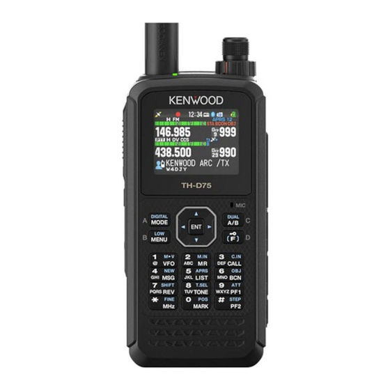
6 APPENDIX 6 APPENDIX 6.1 Exterior views The pictures below are the TH-D75A and the TH-D75E. The TH-D75A is equipped with a Triband Antenna (144/ 220/ 430 MHz band). TH-D75A TH-D75E... -
Page 65: Th-D75A / Th-D75E Specifications
KNB-75LA TH-D75A: 346 g (12.20 oz)/ TH-D75E: 344 g (12.13 oz) (w/ Antenna, Belt Clip) with KBP-9 TH-D75A: 391 g (12.79 oz)/ TH-D75E: 389 g (13.72 oz) (w/ Antenna, Belt Clip, AAAx6 Battery) TRANSMITTER RF Power Output EXT.PS 13.8 V / Battery:7.4 V 0.5 W... - Page 66 Amateur Band FM 12dB SINAD FM/ NFM 144 MHz 0.18/ 0.22 uV 0.19/ 0.24 uV FM/ NFM 220 MHz (TH-D75A only) 0.18/ 0.22 uV 0.20/ 0.25 uV FM/ NFM 430 MHz 0.18/ 0.22 uV 0.20/ 0.25 uV DV PN9/GMSK 4.8kbps, BER 1% 144 MHz (TH-D75A) 0.22 uV...
- Page 68 TH-D75A/E Operating Tips May 17, 2024 Copyright © 2024 JVCKENWOOD Corporation All Rights Reserved...
Need help?
Do you have a question about the TH-D75A and is the answer not in the manual?
Questions and answers