HP SN3000B Reference Manual
B-series 16gb switches
Hide thumbs
Also See for SN3000B:
- Administrator's manual (584 pages) ,
- Troubleshooting manual (138 pages) ,
- Quickspecs (21 pages)
Table of Contents
Advertisement
Quick Links
HP B-series 16Gb Switches Hardware
Reference Guide
Abstract
This document provides information on installing, configuring, and maintaining the HP SN6000B Fibre Channel Switch and
the HP SN3000B Fibre Channel Switch. It is intended for system administrators and technicians with knowledge of SANs and
HP FC switches.
HP Part Number: 5697- 1 522
Published: March 2012
Edition: 2
Advertisement
Table of Contents

Related Manuals for HP SN3000B


Summary of Contents for HP SN3000B
- Page 1 Abstract This document provides information on installing, configuring, and maintaining the HP SN6000B Fibre Channel Switch and the HP SN3000B Fibre Channel Switch. It is intended for system administrators and technicians with knowledge of SANs and HP FC switches. HP Part Number: 5697- 1 522...
- Page 2 © Copyright 201 1, 2012 Hewlett-Packard Development Company, L.P. © Copyright 201 1, 2012 Brocade Communications Systems, Incorporated Confidential computer software. Valid license from HP required for possession, use or copying. Consistent with FAR 12.21 1 and 12.212, Commercial Computer Software, Computer Software Documentation, and Technical Data for Commercial Items are licensed to the U.S. Government under vendor's standard commercial license.
-
Page 3: Table Of Contents
Port side of the switch......................9 Nonport side of the switch....................9 Software options........................9 ISL Trunking........................10 Hardware options......................11 SFP transceivers......................11 HP SN3000B 16Gb FC Switch....................12 Overview..........................12 Platform capabilities......................12 Platform components......................13 Port side of the switch......................13 Nonport side of the switch....................14 Software options........................14 ISL Trunking........................14... - Page 4 Disabling and enabling AG mode..................33 Enabling AG mode.......................34 Disabling AG mode......................34 3 Operating HP 16Gb FC Switches...............35 Powering the switch on and off....................35 LEDs.............................35 POST and boot specifications....................37 POST..........................37 Boot..........................38 Switch maintenance........................38 Diagnostic tests........................38 Switch management........................39 FRU removal and replacement....................39 Replacing a power supply and fan assembly.................39 Determining the status of a power supply and fan assembly..........40 Removing a power supply and fan assembly..............40...
- Page 5 TS/HS dual language sheet....................53 Japanese notices........................54 Japanese VCCI-A notice......................54 Japanese VCCI-B notice......................55 Japanese VCCI marking.....................55 Japanese power cord statement...................55 Korean notices........................55 KCC statement........................55 Class B equipment......................55 Taiwanese notices........................55 BSMI Class A notice......................55 Taiwan battery recycle statement..................56 Turkish recycling notice......................56 Vietnamese Information Technology and Communications compliance marking.......56 Laser compliance notices......................56 English laser notice......................56 Dutch laser notice......................57...
- Page 6 Grounding methods........................66 Glossary....................67 Index......................69 Contents...
-
Page 7: Hp 16Gb Fc Switches
1 HP 16Gb FC Switches This chapter provides general information about the HP SN3000B 16Gb FC Switch and the HP SN6000B 16Gb FC Switch. NOTE: For descriptions of acronyms and abbreviations used in this guide, see the “Glossary”. HP SN6000B 16Gb FC Switch This section provides an overview of the HP SN6000B 16Gb FC Switch. -
Page 8: Platform Components
VF support improves isolation between VFs. FCR service, available with the optional Integrated Routing license, provides improved scalability and fault isolation. FICON, FICON Cascading, and FICON CUP ready. ISL Trunking (licensable), which allows up to eight ports (at 4, 8, or 16 Gb/s) between a pair of switches combined to form a single, logical ISL with a speed of up to 128 Gb/s (256 Gb/s full duplex) for optimal bandwidth utilization and load balancing. -
Page 9: Port Side Of The Switch
Voltage and temperature monitoring. RTC with battery. Port side of the switch Figure 1 (page 9) shows the port side of the HP SN6000B 16Gb FC Switch. Figure 1 Port side view of the HP SN6000B 16Gb FC Switch 1. System status LED 2. -
Page 10: Isl Trunking
◦ ISL Trunking Extended Fabric ◦ Server Application Optimization ◦ Advanced Performance Monitor ◦ Extended Fabric Fabric Watch Advanced Performance Monitor ISL Trunking HP SN6000B 10Gb Integrated FC Extension (enables 10Gb FC for first eight ports) Integrated Routing SN6000B 16Gb 24-48 12-port FC Upgrade LTU NOTE: For the latest information on supported software components, see the product QuickSpecs available from the HP website:... -
Page 11: Hardware Options
Hardware options Table 1 Optional hardware kits Hardware kit Part number HP OM3 LC-LC Optical Cables 0.5m HP OM3 LC/LC Multi-mode Optical Cable AJ833A 1m HP OM3 LC/LC Multi-mode Optical Cable AJ834A 2m HP OM3 LC-LC Multi-mode Optical Cable AJ835A 5m HP OM3 LC-LC Multi-mode OM3 Optical Cable AJ836A 15m HP OM3 LC-LC Multi-mode OM3 Optical Cable AJ837A 30m HP OM3 LC-LC Multi-mode OM3 Optical Cable AJ838A... -
Page 12: Hp Sn3000B 16Gb Fc Switch
Overview The HP SN3000B 16Gb FC Switch is a 24-port autosensing 4, 8, or 16 Gb/s FC switch that delivers the latest HP single-chip architecture for FC SANs. The HP SN3000B 16Gb FC Switch is a small-to-midsize business-class switch that is designed to handle smaller-scale SAN requirements. -
Page 13: Platform Components
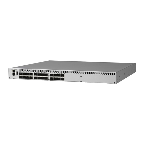
Port side of the switch Figure 4 (page 13) shows the port side of the HP SN3000B 16Gb FC Switch. Figure 4 Port side view of the HP SN3000B 16Gb FC Switch 1. System status LED 2. Management Ethernet port with LEDs 3. -
Page 14: Nonport Side Of The Switch
ISL Trunking is optional software that enables creating trunking groups of ISLs between adjacent switches. Up to eight FC ports on the HP SN3000B 16Gb FC Switch can be used as a trunking group to achieve speeds of up to 128 Gb/s (256 Gb/s full duplex) for optimal bandwidth utilization and load balancing. -
Page 15: Hardware Options
5m HP PremierFlex OM4 LC/LC Multi-mode Optical Cable QK734A 15m HP PremierFlex OM4 LC/LC Multi-mode Optical Cable QK735A 30m HP PremierFlex OM4 LC/LC Multi-mode Optical Cable QK736A 50m HP PremierFlex OM4 LC/LC Multi-mode Optical Cable QK737A HP SN3000B 16Gb FC Switch... -
Page 16: Sfp Transceivers
NOTE: For the latest information on supported hardware components, see the product QuickSpecs available from the HP website: http://www.hp.com/go/sn3000b/quickspecs SFP transceivers Table 4 SFP transceiver options Option Part number 8 Gb Transceivers AJ716B HP 8Gb Shortwave B-series FC SFP+ AJ717A HP 8Gb LW B-series 10km FC SFP+... -
Page 17: Installing And Configuring Hp 16Gb Fc Switches
HP SN3000B 16Gb FC Switch with one integrated power supply/fan assembly NOTE: The HP SN3000B 16Gb FC Switch can, as an option, be configured with a second power supply/fan assembly, which must be ordered separately. Serial cable with an RJ-45 connector plus an adaptor for RJ-45 to DB9... -
Page 18: Cabling Considerations
Installing the switch This section provides instructions for installing the HP SN6000B 16Gb FC Switch and the HP SN3000B 16Gb FC Switch. Items required for installation To set up the switch for the first time, you will need the following:... -
Page 19: Installing The Switch In A Rack Using The Rack Mount Kit
HP SAN Compatibility Tool at http://hpsancompat.com/. Installing the switch in a rack using the Rack Mount Kit Use the SN6000B and the SN3000B Switch Rack Mount Kits to install the switch in an HP 10000 Series Rack. CAUTION: Install the Rack Mount Kits as described in this section so that when the switch is installed, the port side faces the rear of the rack. - Page 20 Rack mount installation To install the switch in a rack using the Rack Mount Kit: Place the switch on a flat surface and attach each inner rail to the switch using three flat-head screws. See Figure 7 (page 20). The rails are labeled Left and Right to designate the left side and right side of the switch as viewed from its nonport side.
- Page 21 Attach each outer rail as shown in Figure 9 (page 21). The rails are labeled Left and Right to designate the left side and right side of the rack as viewed from the front of the cabinet. Figure 9 Attaching the outer rails Slide each rail over the rear mounting brackets.
- Page 22 At the front of the rack, run the switch power cords from the sides of the rack through the cutouts in the rail, and then connect them to the switch power supplies. Connect two power cords to the SN6000B 48-port switch. Connect one power cord to the SN3000B 24-port switch. See Figure 1 1 (page 23).
- Page 23 SN3000B 24–port switch.) NOTE: If you are configuring the second (optional) power supply, the SN3000B switch will also have two power cords. Power on the power supplies by setting both power switches to the ON (I) position.
-
Page 24: Installing A Standalone Switch
AC failure. For the SN3000B switch, connect a power cord to either the single power supply present or to both power supplies, if an optional second power supply is present. Then connect the power cords to power sources on separate circuits to protect against AC failure. -
Page 25: Connecting The Serial Cable
Ethernet and FC cables Disk array with FC ports Browser that allows pop-up windows If you are using static IP addressing, you will need the following items (not required if using DHCP): ◦ Fixed IP address (IPv4 or IPv6) for the switch ◦... -
Page 26: Using Dhcp To Set The Ip Address
Using DHCP to set the IP address When using DHCP, the switch obtains its IP address, subnet mask, and default gateway address from the DHCP server. The DHCP client can connect only to a DHCP server that is on the same subnet as the switch. -
Page 27: Setting The Time Zone
Enter the date command: date "mmddHHMMyy" The values are as follows: mm is the month; valid values are 01 through 12. dd is the date; valid values are 01 through 31. HH is the hour; valid values are 00 through 23. MM is minutes;... -
Page 28: Synchronizing Local Time
Log in to the switch using the default password password. Use timezone_fmt to set the time zone by Country/City or by time zone ID, such as PST. The following example shows how to change the time zone to US/Central: switch:admin> tstimezone Time Zone : US/Pacific switch:admin>... -
Page 29: Configuring The Zones And Selecting Devices
Enter the tsclockserver command: switch:admin> tsclockserver "<ntp1;ntp2> The value ntp1 is the IP address or DNS name of the first NTP server, which the switch must be able to access. The value ntp2 is the name of the second NTP server and is optional. The entire operand "<ntp1;ntp2>... - Page 30 Install the SFP+ transceivers in the FC ports on the switch to match the ports displayed in the Device Connection window . If you are using an SFP+ transceiver that does not have a pull tab, ensure that the wire bail is in the unlocked position.
-
Page 31: Setting Switch Features
Connect the FC cables from the switch to your host and storage devices. Ensure that the physical connections match the connections displayed in the Device Connection window. Remove the plastic protector caps from the FC cable ends (if there are any) and position the cable connector so that it is oriented correctly. -
Page 32: Verifying The Configuration
Verifying the configuration To confirm that the switch is configured and ready for use: Observe the LEDs to verify that all components are functional. For information about LED patterns, see “LEDs” (page 35). Issue the switchshow command from the workstation. This command provides information about the switch and port status. -
Page 33: Fabric Os Native And Ag Modes
In AG mode, cascading is not available for the switch. See the Access Gateway Administrator’s Guide for details on any restrictions. In Native mode, the SN6000B switch provides up to 48 external FC ports and the SN3000B switch provides up to 24 external FC ports. These universal self-configuring ports are capable of becoming one of the following port types: ◦... -
Page 34: Enabling Ag Mode
Enabling AG mode Note the following when enabling AG mode: After you enable AG mode, some fabric information is erased, such as the zone and security databases. Enabling AG mode is disruptive because the switch is disabled and rebooted. Ensure that no zoning or AD transaction buffers are active. If a transaction buffer is active, enabling AG mode fails with the error Failed to clear Zoning/Admin Domain configuration. -
Page 35: Operating Hp 16Gb Fc Switches
3 Operating HP 16Gb FC Switches This chapter discusses switch power, LEDs, maintenance, and management. Powering the switch on and off Power switches are located on the nonport side of the switch. If the switch is mounted in a rack, you must remove the plenum to access the power switches. Power is supplied to the switch as soon as the first power supply is connected and powered To power the switch off, power off the power supplies present by setting the AC power switch to O. - Page 36 Table 5 Port side LED patterns LED name LED color Status of hardware Recommended action System power No light System is off or there is an internal Verify that the system is powered on (power (green) power supply failure. supply switches set to I), the power cables are attached, and the power source is live.
-
Page 37: Post And Boot Specifications
The nonport side of the switch has one LED per power supply/fan assembly. See Figure 17 (page 37). The standard configuration of the HP SN3000B 16Gb FC Switch includes a single power supply/fan assembly. Table 6 (page 37) describes the status. -
Page 38: Boot
NOTE: Diagnostic tests can temporarily lock the transmit and receive speed of the links. HP does not support 2Gb connectivity to the SN6000B or the SN3000B switches. For information about specific diagnostic tests, see the Fabric OS Troubleshooting and Diagnostics Guide. -
Page 39: Switch Management
Each FRU contains two fans. The system software measures and sets fan speed through the tachometer interface. The SN3000B switch comes with one power supply and fan assembly. Fabric OS identifies the assemblies from right to left on the nonport side. Even though they are contained within a single unit, the power supply and fan components are identified separately. -
Page 40: Determining The Status Of A Power Supply And Fan Assembly
If the switch has two power supply and fan assemblies, go to step 3. When replacing the power supply and fan assembly in an HP SN3000B 16Gb FC Switch that has only one assembly, the switch must be powered off before removing the assembly. - Page 41 Power off the power supply to be replaced by setting the AC power switch to the off (O) position. The fans in the other power supply automatically switch to high speed to maintain adequate cooling. Unplug the power cord from the power supply and fan assembly being replaced. Unscrew the captive screw using a Phillips screwdriver.
-
Page 42: Installing A Power Supply And Fan Assembly
Installing a power supply and fan assembly To install the power supply and fan assembly: Ensure that the replacement FRU AC power switch is in the off (O) position. CAUTION: Damage to the switch can result if the AC power switch is in the on (|) position when the switch is installed in the chassis. -
Page 43: Support And Other Resources
4 Support and other resources HP technical support For worldwide technical support information, see the HP support website: http://www.hp.com/support Before contacting HP, collect the following information: Product model names and numbers Technical support registration number (if applicable) Product serial numbers Error messages Operating system type and revision level Detailed questions... -
Page 44: Hp Websites
HP websites For additional information, see the following HP websites: http://www.hp.com http://www.hp.com/go/storage http://www.hp.com/service_locator http://www.hp.com/support/manuals http://www.hp.com/support/downloads Rack stability Rack stability protects personnel and equipment. WARNING! To reduce the risk of personal injury or damage to equipment: Extend leveling jacks to the floor. Ensure that the full weight of the rack rests on the leveling jacks. -
Page 45: Typographic Conventions
Typographic conventions Table 8 Document conventions Convention Element Blue text: Table 8 (page 45) Cross-reference links and email addresses Blue, underlined text: http://www.hp.com Website addresses Bold text Keys that are pressed Text entered into a GUI element, such as a box GUI elements that are clicked or selected, such as menu and list items, buttons, tabs, and check boxes Italic text... -
Page 46: A Specifications
A Specifications This appendix provides switch specifications. Physical specifications Table 9 Physical specifications Dimension Value Height 1U or 4.3 cm (1.7 in) Depth (without plenum) 44.3 cm (17.4 in) Width (The slightly increased width requires a slim rail 43.8 cm (17.2 in) rack mount kit for mounting.) Weight (with two power supply and fan assemblies, and 9.2 kg (20.2 lb) -
Page 47: Environmental Requirements
System power consumption 1 10 W with all 48 ports populated with 16 Gb/s SWL optical media 72 W with empty chassis and no optical media Table 12 HP SN3000B 16Gb FC Switch power supply specifications Specification Values Input voltage Range: 85–264 VAC, nominal: 100–240 VAC... -
Page 48: General Specifications
Less than 700 ns with no contention (destination port is free) Aggregate switching capacity 420 million frames per second (for Class 2, Class 3, and Class F frames for the 48 port chassis) Table 15 HP SN3000B 16Gb FC Switch general specifications Specification Description Configurable port types... -
Page 49: Memory Specifications
NOTE: HP does not support 2 Gb/s connectivity to the HP SN6000B 16Gb FC Switch or the HP SN3000B 16Gb FC Switch. Serial port specifications The serial port is located on the port side of the switch and uses an RJ-45 connector for the serial port. -
Page 50: Ag Default Port Mapping
10–14 mapped to 42 15–19 mapped to 43 20–24 mapped to 44 25–29 mapped to 45 30–34 mapped to 46 35–39 mapped to 47 Table 20 HP SN3000B 16Gb FC Switch AG default port mapping Total ports F_Ports N_Ports Default port mapping 0–15 16–23... -
Page 51: B Regulatory Compliance Notices
B Regulatory compliance notices This appendix contains regulatory notices for the switch. Regulatory compliance identification numbers For the purpose of regulatory compliance certifications and identification, this product has been assigned a unique regulatory model number. The regulatory model number can be found on the product nameplate label, along with all required approval markings and information. -
Page 52: Declaration Of Conformity For Products Marked With The Fcc Logo, United States Only
Or call 1-281-514-3333 Modification The FCC requires the user to be notified that any changes or modifications made to this device that are not expressly approved by Hewlett-Packard Company may void the user's authority to operate the equipment. Cables When provided, connections to this device must be made with shielded cables with metallic RFI/EMI connector hoods in order to maintain compliance with FCC Rules and Regulations. -
Page 53: Chinese Notices
This marking is valid for non-Telecom products and EU harmonized Telecom products (e.g., Bluetooth). Certificates can be obtained from http://www.hp.com/go/certificates. Hewlett-Packard GmbH, HQ-TRE, Herrenberger Strasse 140, 71034 Boeblingen, Germany Chinese notices This is a class A product. In a domestic environment this product may cause radio interference in which case the user may be required to take adequate measures. -
Page 54: Japanese Notices
Japanese notices Japanese VCCI-A notice Regulatory compliance notices... -
Page 55: Japanese Vcci-B Notice
Japanese VCCI-B notice Japanese VCCI marking Japanese power cord statement Korean notices KCC statement Class A device (Broadcasting Communication Device for Office Use): This device obtained EMC registration for office use (Class A), and may be used in places other than home. Sellers and/or users need to take note of this. -
Page 56: Taiwan Battery Recycle Statement
Taiwan battery recycle statement Turkish recycling notice Türkiye Cumhuriyeti: EEE Yönetmeliğine Uygundur Vietnamese Information Technology and Communications compliance marking Laser compliance notices English laser notice This device may contain a laser that is classified as a Class 1 Laser Product in accordance with U.S. -
Page 57: Dutch Laser Notice
Dutch laser notice French laser notice German laser notice Laser compliance notices... -
Page 58: Italian Laser Notice
Italian laser notice Japanese laser notice Spanish laser notice Regulatory compliance notices... -
Page 59: Recycling Notices
Recycling notices English recycling notice Disposal of waste equipment by users in private household in the European Union This symbol means do not dispose of your product with your other household waste. Instead, you should protect human health and the environment by handing over your waste equipment to a designated collection point for the recycling of waste electrical and electronic equipment. -
Page 60: Estonian Recycling Notice
Estonian recycling notice Äravisatavate seadmete likvideerimine Euroopa Liidu eramajapidamistes See märk näitab, et seadet ei tohi visata olmeprügi hulka. Inimeste tervise ja keskkonna säästmise nimel tuleb äravisatav toode tuua elektriliste ja elektrooniliste seadmete käitlemisega egelevasse kogumispunkti. Küsimuste korral pöörduge kohaliku prügikäitlusettevõtte poole. Finnish recycling notice Kotitalousjätteiden hävittäminen Euroopan unionin alueella Tämä... -
Page 61: Italian Recycling Notice
Italian recycling notice Smaltimento di apparecchiature usate da parte di utenti privati nell'Unione Europea Questo simbolo avvisa di non smaltire il prodotto con i normali rifi uti domestici. Rispettare la salute umana e l'ambiente conferendo l'apparecchiatura dismessa a un centro di raccolta designato per il riciclo di apparecchiature elettroniche ed elettriche. -
Page 62: Romanian Recycling Notice
Romanian recycling notice Casarea echipamentului uzat de către utilizatorii casnici din Uniunea Europeană Acest simbol înseamnă să nu se arunce produsul cu alte deşeuri menajere. În schimb, trebuie să protejaţi sănătatea umană şi mediul predând echipamentul uzat la un punct de colectare desemnat pentru reciclarea echipamentelor electrice şi electronice uzate. -
Page 63: Battery Replacement Notices
Battery replacement notices Dutch battery notice French battery notice Battery replacement notices... -
Page 64: German Battery Notice
German battery notice Italian battery notice Regulatory compliance notices... -
Page 65: Japanese Battery Notice
Japanese battery notice Spanish battery notice Battery replacement notices... -
Page 66: C Electrostatic Discharge And Grounding Recommendations
C Electrostatic discharge and grounding recommendations Electrostatic discharge recommendations CAUTION: To prevent damaging the system, be aware of the precautions you need to follow when setting up the system or handling parts. A discharge of static electricity from a finger or other conductor may damage system boards or other static-sensitive devices. - Page 67 Glossary This glossary defines acronyms and terms used in this guide or related to this product. It is not a comprehensive glossary of computer terms. Admin Domain. Access Gateway. Advanced Performance Monitoring. Control Unit Port. DDR2 Double data rate 2. DHCP Dynamic Host Configuration Protocol.
- Page 68 Coordinated Universal Time. Virtual Fabric. World Wide Name. Glossary...
- Page 69 Canadian notice, Chinese notices, commands installing and configuring the switch, licenseadd, ISL trunking groups licenseshow, HP SN3000B 16Gb FC Switch, portenable, HP SN6000B 16Gb FC Switch, portshow, 32, portstart, conventions Japanese notices, document, text symbols,...
- Page 70 installing and configuring, SN6000B 16Gb FC Switch installing and configuring, status policy, Subscriber's Choice, HP, switch status policy, symbols in text, Taiwanese notices, technical support service locator website, text symbols, warning rack stability, websites customer self repair, HP , HP Subscriber's Choice for Business, product manuals, Index...
Need help?
Do you have a question about the SN3000B and is the answer not in the manual?
Questions and answers