Table of Contents
Advertisement
Quick Links
Download this manual
See also:
User Manual
Advertisement
Table of Contents

Related Manuals for Acer TravelMate 4010 Series


Summary of Contents for Acer TravelMate 4010 Series
- Page 1 Acer TravelMate 4010 Series Service Guide Service guide files and updates are available on the ACER/CSD web; for more information, please refer to http://csd.acer.com.tw PRINTED IN TAIWAN...
-
Page 2: Revision History
Revision History Please refer to the table below for the updates made on TravelMate 4010 service guide. Date Chapter Updates... - Page 3 Copyright Copyright © 2005 by Acer Incorporated. All rights reserved. No part of this publication may be reproduced, transmitted, transcribed, stored in a retrieval system, or translated into any language or computer language, in any form or by any means, electronic, mechanical, magnetic, optical, chemical, manual or otherwise, without the prior written permission of Acer Incorporated.
- Page 4 Conventions The following conventions are used in this manual: Denotes actual messages that appear SCREEN MESSAGES on screen. NOTE Gives bits and pieces of additional information related to the current topic. WARNING Alerts you to any damage that might result from doing or not doing specific actions.
- Page 5 DIFFERENT part number code to those given in the FRU list of this printed Service Guide. You MUST use the list provided by your regional Acer office to order FRU parts for repair and service of customer machines.
-
Page 7: Table Of Contents
Table of Contents Chapter 1 System Specifications Features ............1 System Block Diagram . - Page 8 Table of Contents Disassembling the External Modules ........67 Disassembling the HDD Module .
-
Page 9: System Specifications
Chapter 1 System Specifications Features Below is a brief summary of the computer’s many feature: Performance ® ® Intel Pentium M processor 725, 725A or higher ® Intel 855GME chipset 256/512 MB of DDR333 SDRAM standard, upgradeable to 2048 MB with dual soDimm modules 60/80/100GB and above high-capacity, Enhanced-IDE hard disk Advanced Configuration Power Interface (ACPI) power management system. - Page 10 Ergonomically-centered touchpad pointing device Acer FineTouch keyboard with a 5-degree curve Internet 4-way scroll button Keyboard and Pointing Device 88/89-key Windows keyboard Ergonomically-centered touchpad pointing device with scroll function Acer FineTouch keyboard with a 5-degree curve Expansion One Type II CardBus PC Card slot...
-
Page 11: System Block Diagram
System Block Diagram Chapter 1... -
Page 12: Board Layout
Board Layout Top View Keyboard Connector No 3 in 1 Connector for TM4010 Bluetooth Board Connector Speaker Connector LCD Cable Connector Internal Microphone Connector LED Board Connector Modem Board Connector Lid Switch Touchpad Board Connector Modem Cable Connector Chapter 1... -
Page 13: Bottom View
Bottom View Power Jack Audio Cable Connector Line-in Connector No docking port for TM4010 Headphone Out Connector Audio Cable Connector Microphone-in Connector Main Battery Connector USB Connector ODD Connector No IEEE 1394 Connector for TM4010 Media Bay Connector PCMCIA Mini PCI Slot USB Connector Second Battery Connector CPU Socket... - Page 14 No IR for TM4010 LAN Cable Connector Bluetooth Switch FAN Connector Wireless Switch LAN Cable Connector Chapter 1...
-
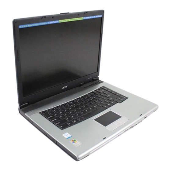
Page 15: A Travelmate Tour
A TravelMate tour After knowing your computer features, let us show you around your new TravelMate computer. Front Open View Icon Item Description Display screen Also called LCD (liquid-crystal display), displays computer output. Microphone Internal microphone for sound recording. Keyboard Inputs data into your computer. - Page 16 Power button Turns the computer on and off. Chapter 1...
-
Page 17: Front Closed View
Front Closed View Icon Item Description Speakers Left and right speakers deliver stereo audio output. Power indicator Lights when the computer is on. Battery indicator Lights when the battery is being charged ® Indicates that (optional) Bluetooth is Bluetooth communications enabled. -
Page 18: Left View
Left View Icon Item Description Optical drive Internal optical drive; accepts CDs or DVDs depending on the optical drive type. LED indicator Lights up when the optical drive is active. Emergency eject hole Ejects the optical drive tray when the computer is turned off. -
Page 19: Right Panel
Right Panel Icon Item Description PC Card slot eject Ejects the PC Card from the slot. button PC Card slot Connects to one Type II CardBus PC Card. Two USB 2.0 ports Connects to Universal Serial Bus (USB) 2.0 devices (e.g., USB mouse, USB camera). Ethernet (RJ-45) Port Connect to an Ethernet 10/100-based network. -
Page 20: Rear Panel
Rear Panel Icon Item Description Power jace Connects to an AC adapter. External display port Connects a display device (e.g., external monitor, LCD projector). Security keylock Connects to a Kensington-compatible computer security lock. Chapter 1... -
Page 21: Bottom Panel
Bottom Panel Item Description Cooling fan Helps keep the computer cool. Note: Do not cover or obstruct the opening of the fan. Battery lock Locks the battery in place. Memory compartment Houses the computer’s main memory. Hard disk bay Houses the computer’s hard disk (secured by a screw). -
Page 22: Indicators
Indicators The computer has three easy-to-read status icons on the upper-right above the keyboard, and four on the front panel. Icon Function Description Caps lock Lights when Caps Lock is activated. Num lock Lights when Num Lock is activated. Media Activity Lights when the disc or AcerMedia is activated. -
Page 23: Using The Keyboard
Using the Keyboard The keyboard has full-sized keys and an embedded keypad, separate cursor keys, two Windows keys and twelve function keys. Lock Keys and embedded Numeric Keypad The keyboard has three lock keys which you can toggle on and off. Lock Key Description Caps Lock... -
Page 24: Windows Keys
Windows Keys The keyboard has two keys that perform Windows-specific functions. Icon Description Windows key Pressed alone, this key has the same effect as clicking on the Windows Start button; it launches the Start menu. It can also be used with other keys to provide a variety of function: + Tab (Activates next taskbar button) + E (Explores My Computer) -
Page 25: Hot Keys
Description Fn-F1 Hot key help Displays help on hot keys. Fn-F2 Acer eSetting Launches the Acer eSetting in the Acer eManager set by the Acer Empowering key. Fn-F3 Acer Launches the Acer ePowerManagement in the Acer ePowerManagement eManager set by the Acer Empowering key. - Page 26 Hot Key Icon Function Description Fn-y Volume down Decreases the speaker volume. Fn-x Brightness up Increases the screen brightness. Fn-z Brightness down Decreases the screen brightness Chapter 1...
-
Page 27: Special Key
Special Key You can locate the Euro symbol and US dollar sign at the upper-center and/or bottom-right of your keyboard. To type: The Euro symbol Open a text editor or word processor. Either directly press the Euro symbol at the bottom-right of the keyboard, or hold <Alt Gr> and then press the <5>... -
Page 28: Launch Keys
Web browser, Empowering and programmable keys. Press the Acer Empowering Key to run the Acer EManager. The mail and Web browser are default for Email and Internet programs, but can be reset by users. To set the mail, Web browser and programmable keys, run the acer Launch Manager. - Page 29 In addition, there are two launch keys at the front panel. Even when the cover is closed, you can easily access ® the features of Wireless and Bluetooth . However, the Wireless and Bluetooth keys cannot be set by users. Description Default application Lights to indicate the status of Bluetooth...
-
Page 30: Touchpad
Touchpad The built-in touchpad is a PS/2-compatible pointing device that senses movement on its surface. This means the cursor responds as you move your finger on the surface of the touchpad. The central location on the palmrest provides optimum comfort and support. NOTE: If you are using an external USB or serial mouse, you can press Fn-F7 to disable the touchpad. - Page 31 Function Left Button Right Button Scroll Button Scroll Click and hold the button in the desired direction (up/ down/left/right) NOTE: Keep your fingers dry and clean when using the touchpad. Also keep the touchpad dry and clean. The touchpad is sensitive to finger movements. Hence, the lighter the touch, the better the response. Tapping too hard will not increase the touchpad’s responsiveness.
-
Page 32: Hardware Specifications And Configurations
Hardware Specifications and Configurations Processor Item Specification CPU type ® Intel Pentium M 715,725 TravelMate 4010 Core logic ® Inte 855GME+ICH4-M for TravelMate 4010 CPU package Intel socketable 478pin Micro-BGA CPU core voltage 1.308V (highest frequency mode) to 0.956V (low frequency mode) 0.748V (deeper sleep mode) - Page 33 Memory Combinations Slot 1 Slot 2 Total Memory 128MB 128MB 256MB 256MB 512MB 512MB 1024MB 1024MB 128MB 128MB 256MB 128MB 256MB 384MB 128MB 512MB 640MB 1284MB 1024MB 1152MB 256MB 128MB 384MB 256MB 256MB 512MB 256MB 512MB 768MB 256MB 1024MB 1280MB 512MB 128MB 640MB...
- Page 34 Modem Interface Item Specification Supports modem protocol V.90/V.92 Modem connector type RJ11 Modem connector location Right panel Bluetooth Interface Item Specification Chipset Broadcom BCM2035 Data throughput 723 bps (full speed data rate) Protocol Bluetooth 1.1 (Upgradeable to Bluetooth 1.2 when SIG specification is ratified).
- Page 35 Hard Disk Drive Interface Item Specification Max. media transfer rate (disk-buffer, Mbytes/s) Data transfer 100 MB/Sec. 100 MB/Sec. 100 MB/Sec. 100 MB/Sec. rate Ultra DMA mode-5 Ultra DMA mode-5 Ultra DMA mode-5 Ultra DMA mode-5 (host~buffer, Mbytes/s) DC Power Requirements Voltage 5V(DC) +/- 5% 5V(DC) +/- 5%...
- Page 36 DVD-Dual Interface Item Specification Applicable disc format Support disc formats 1. Reads data in each CD-ROM, CD-ROM XA, CD-1, Video CD, CD-Extra and CD-Text 2. Reads data in Photo CD (single and Multi-session) 3. Reads standard CD-DA 4. Reads and writes CD-R discs 5.
- Page 37 Supports ZV (Zoomed Video) port No ZV support Supports 32 bit CardBus System Board Major Chips Item Controller Core logic ® Intel 855GME+ICH4 (TravelMate 4010) built-in north bridge BroadCom BCM4401 (10/100M) IEEE 1394 TI PC7411 USB 2.0 ICH4-M Super I/O controller NS 87383...
- Page 38 System Board Major Chips Item Controller PCMCIA TI PC7411 Audio Conexant CX20468-31 3-in-1 card reader TI PC7411 Keyboard Item Specification Keyboard controller NS PC97551 Total number of keypads 88-/89-key Windows logo key Internal & external keyboard work 1. Plug USB keyboard to the USB port directly: Yes simultaneously 2.
- Page 39 LCD 14.1 inch (There is no 14.1 LCD for this model) Item Specification Typical Power Consumption (watt) 4.03 (for backlight unit) Weight 400g (w/o inverter) 420g 460g Physical Size(mm) 299(W)x228(H)x5.5 299(W)x228(H)x5.2 299(W)x228(H)x6.2 Electrical Interface R/G/B Data, 3Sync, 1 channel LVDS 1 channel LVDS Signals, Clock (4 pairs LVDS)
- Page 40 LCD 15 inch and 15.4 inch Item Specification Vendor & model name SAMSUNG Hitachi LCD 15.4" WXGA LTN150XB-L03 TX38D81VC1CAB Screen Diagonal (mm) 15.0 inches, 381 390.1 Active Area (mm) 304.1x228.1 304.1x228.1 331.2x207.0 Display resolution (pixels) 1024x768 XGA 1024x768 XGA 1280x800 WXGA Pixel Pitch 0.297x0.297 0.297x0.297...
- Page 41 AC Adaptor Item Specification Maximum input AC current 1.7A Inrush current 220A@115VAC 220A@230VAC Efficiency 82% min. @115VAC input full load System Power Management ACPI mode Power Management Mech. Off (G3) All devices in the system are turned off completely. Soft Off (G2/S5) OS initiated shutdown.
- Page 42 Chapter 1...
-
Page 43: System Utilities
System BIOS Ver: 3A01 Montara-GME3360 VGA BIOS Ver: PQ1A24 KBC Ver: 1234567890123456789012 Serial Number Asset Tag Number: 1234567890 Product Aspire1680 Manufacturer Name: Acer xxxxxxxxxxxxxxxxxxxxxxxxxxxxxxxx UUID: Help ↑ ↓ Select Item F5/F6 Change Values Setup Defaults ← → Exit Select Menu Enter... -
Page 44: Navigating The Bios Utility
Navigating the BIOS Utility There are six menu options: Info., Main, System Devices, Security, Boot, and Exit. Follow these instructions: To choose a menu, use the cursor left/right keys (zx). To choose a parameter, use the cursor up/down keys ( wy). To change the value of a parameter, press por q. -
Page 45: Information
System BIOS Ver: 3A01 Montara-GME3360 VGA BIOS Ver: PQ1A24 KBC Ver: 1234567890123456789012 Serial Number Asset Tag Number: 1234567890 Product Aspire1680 Manufacturer Name: Acer xxxxxxxxxxxxxxxxxxxxxxxxxxxxxxxx UUID: Help Select Item F5/F6 Change Values Setup Defaults ↑ ↓ ← → Exit Select Menu Enter... -
Page 46: Main
Main The Main screen displays a summary of your computer hardware information, and also includes basic setup parameters. It allows the user to specify standard IBM PC AT system parameters. PhoenixBIOS Setup Utility Info. Advanced Security Boot Exit Main Item Specific Help System Time: [05:34:07] System Date:... - Page 47 The table below describes the parameters in this screen. Settings in boldface are the default and suggested parameter settings. Parameter Description Format/Option System Time Sets the system time. The hours are displayed Format: HH:MM:SS with 24-hour format. (hour:minute:second) System Time System Date Sets the system date.
-
Page 48: Advanced
Advanced The Advanced menu screen contains parameters involving your hardware devices. It also provides advanced settings of the system. PhoenixBIOS Setup Utility Info. Main Advanced Security Boot Exit Item Specific Help Internal Touchpad: [Both] Configure Infrared Port using options: Infrared Port (FIR): [Enabled] [Disable] No configuration... - Page 49 Parameter Description Options Disabled Legacy USB Support Enables, disables USB interface devices support. Option: or Enabled (Enable for use with a non-USB aware Operating System such as DOS or UNIX). Disabled Hard Disk Recovery Enables or disables Hard Disk to Hard Disk system Option: or Enabled Recovery by pressing Fn+F10 key during POST.
-
Page 50: Security
Security The Security screen contains parameters that help safeguard and protect your computer from unauthorized use. PhoenixBIOS Setup Utility Security Exit Info. Main Advanced Boot Item Specific Help Supervisor Password Is: Clear User Password Is: Clear When shown as [Locked], Primary HardDisk Security: Clear the hard drive password... - Page 51 The table below describes the parameters in this screen. Settings in boldface are the default and suggested parameter settings. Parameter Description Option User Password is Shows the setting of the user password. Clear or Set Supervisor Password is Shows the setting of the Supervisor password Clear or Set Set User Password...
- Page 52 Press e. After setting the password, the computer sets the User Password parameter to “Set”. If desired, you can opt to enable the Password on boot parameter. When you are done, press u to save the changes and exit the BIOS Setup Utility. Removing a Password Follow these steps: Use the w and y keys to highlight the Set Supervisor Password parameter and press the e key.
- Page 53 If the verification is OK, the screen will display as following. The password setting is complete after the user presses u. If the current password entered does not match the actual current password, the screen will show you the Setup Warning. If the new password and confirm new password strings do not match, the screen will display the following message.
-
Page 54: Boot
Boot This menu allows the user to decide the order of boot devices to load the operating system. Bootable devices includes the distette drive in module bay, the onboard hard disk drive and the CD-ROM in module bay. PhoenixBIOS Setup Utility Info. -
Page 55: Exit
Exit The Exit screen contains parameters that help safeguard and protect your computer from unauthorized use. PhoenixBIOS Setup Utility Exit Info. Main Advanced Security Boot Item Specific Help Exit Saving Changes Exit System Setup and save Exit Dicarding Changes your changes to CMOS. Load Setup Defaults Discard Changes Save Changes... -
Page 56: Bios Flash Utility
BIOS Flash Utility The BIOS flash memory update is required for the following conditions: New versions of system programs New features or options Restore a BIOS when it becomes corrupted. Use the Phlash utility to update the system BIOS flash ROM. NOTE: If you do not have a crisis recovery diskette at hand, then you should create a Crisis Recovery Diskette before you use the Phlash utility. - Page 57 Check HDD Master ID number. P h o e n ixB IO S S e tu p U tility In fo . M a in A d va n c e d S e c u rity B o o t E x it Ite m s p e c ific H e lp S u p e rvis o r P a s s w o rd Is :...
- Page 58 Chapter 2...
-
Page 59: Machine Disassembly And Replacement
Chapter 3 Machine Disassembly and Replacement This chapter contains step-by-step procedures on how to disassemble the notebook computer for maintenance and troubleshooting. To disassemble the computer, you need the following tools: Wrist grounding strap and conductive mat for preventing electrostatic discharge Small Philips screw driver Philips screwdriver Plastic flat head screw driver... -
Page 60: General Information
General Information Before You Begin Before proceeding with the disassembly procedure, make sure that you do the following: Turn off the power to the system and all peripherals. Unplug the AC adapter and all power and signal cables from the system. Remove the battery pack. - Page 61 Screw Type Location Quantity M2.5*6 Remove the IO bezel then you will see. (Part number: 86.T23V7.010) M2.5*6 Remove the heatsink cover then you will see. (Part number: 86.T23V7.010) M2.5*6 Remove the HDD cover then you will see. (Part number: 86.T23V7.010) M2.5*3 Detach the HDD module then you will see.
-
Page 62: Disassembly Procedure Flowchart
Disassembly Procedure Flowchart The flowchart on the succeeding page gives you a graphic representation on the entire disassembly sequence and instructs you on the components that need to be removed during servicing. For example, if you want to remove the system board, you must first remove the keyboard, then disassemble the inside assembly frame in that order. - Page 63 LCD Module 4 screw pads LCD Bezel *6 hinges *2 brackets LCD Inverter Antenna set LCD Cover Assembly LCD Cable LCD Brackets Screw List Item Description SCREW M2.0X3.0-I-NI-NYLOK SCREW I2.5*3M-BNIH(M2.5L3) SCREW M2.5*4L-BZN-NYLOK SCREW M2.0X5-I-NI-NYLOK SCREW MM25060IL69 SCREW M2.0*5-I(NI)(NYLOK) SCREW M2.0X2.5-I-NI-NYLOK SCREW I2*3M-NIHY (M2L3) SCREW M1.7*3.0-I (BK) SCREW I3*3.5M-NIH(M3L3.5)
-
Page 64: Removing The Battery Pack
Removing the Battery Pack Unlock the battery lock. Slide the battery latch as shown then remove the battery pack. Chapter 3... -
Page 65: Removing The Hdd Module/The Memory And The Wireless Lan Card/The Thermal Module And The Cpu/Odd Module And Lcd Module
Removing the HDD Module/the Memory and the Wireless LAN Card/the Thermal Module and the CPU/ODD Module and LCD Module Removing the HDD Module Remove the two screws holding the HDD cover. Remove the HDD cover. Detach the HDD module then remove it. Removing the Memory and the Wireless LAN Card Remove the two screws that secure the RAM/Wireless cover. - Page 66 Remove the heatsink cover from the main unit. Disconnect the fan cable. Remove the four screws that secure the thermal module. Pull the thermal module outwards then remove it. NOTE: The edge of the thermal module as shown is very sharp. Be very careful as you remove the thermal module.
-
Page 67: Removing The Odd Module
Removing the ODD Module Remove the three screws holding the middle cover. Detach the middle cover carefully. Turn over the keyboard as shown. Disconnect the keyboard cable from the main board then remove the keyboard. Remove the screw that fastens the ODD module. Turn over the notebook computer then detach the ODD module carefully. - Page 68 Remove the two screws that secure the keyboard as shown. Turn over the keyboard as shown and disconnect the keyboard cable then remove the keyboard. Pull out the antenna set with a tweezers then take out the antenna set from the main unit. Disconnect the LCD coaxial cable.
-
Page 69: Disassembling The Main Unit
Disassembling the Main Unit Separate the Main Unit Into the Upper and the Lower Case Assembly Remove the two screws holding the switch board. Remove the switch board. Disconnect the touchpad FFC from the main board. Disconnect the bluetooth cable. Remove the five screws that secure the upper case. -
Page 70: Disassembling The Lower Case Assembly
Remove the three screws that secure the touchpad board. Remove the touchpad board from the upper case. Disconnect the touchpad board to touchpad FFC. Remove the touchpad board to touchpad FFC from the uppwer case assembly. Remove the four screws holding the touchpad bracket. Detach the touchpad bracket from the upper case assembly. - Page 71 Disconnect the MDC cable from the modem board. Detach the MDC cable from the main board. Remove the two screws holding the modem board. Remove the modem board from the lower case. Disconnect the speaker cable from the main board. Remove the two screws that secure the main board.
- Page 72 Chapter 3...
-
Page 73: Disassembling The Lcd Module
Disassembling the LCD Module Remove the four screw caps as shown. Remove the four screws holding the LCD bezel. Then detach the LCD bezel from the LCD module. Disconnect the inverter board then remove it. Remove the three screws holding the right hinge. Then remove the three screws that secure the left hinge. - Page 74 13. Remove the left bracket as the picture shows. 14. Tear off the tape fastening the LCD cable. 15. Tear off the the LCD cable fastening the LCD cable, then remove it.. Chapter 3...
-
Page 75: Disassembling The External Modules
Disassembling the External Modules Disassembling the HDD Module Remove the two screws holding the HDD bracket on one side. Remove another two screws holding the HDD bracket on the other side. Then take the hard disc drive out from the HDD bracket. Disassembling the Optical Drive Module Remove the four screws as the picture shows. - Page 76 Chapter 3...
-
Page 77: Chapter 4 Troubleshooting
Troubleshooting Use the following procedure as a guide for computer problems. NOTE: The diagnostic tests are intended to test this model. Non-Acer products, prototype cards, or modified options can give false errors and invalid system responses. Duplicate symptom and obtain the failing symptoms in as much detail as possible. -
Page 78: System Check Procedures
System Check Procedures External Diskette Drive Check If an error occurs with the internal diskette drive, reconnect the diskette connector on the system board. If the error still remains: Reconnect the external diskette drive/DVD-ROM module. Replace the external diskette drive/CD-ROM module. Replace the main board. -
Page 79: Power System Check
Power System Check To verify the symptom of the problem, power on the computer using each of the following power sources: Remove the battery pack. Connect the power adapter and check that power is supplied. Disconnect the power adapter and install the charged battery pack; then check that power is supplied by the battery pack. -
Page 80: Touchpad Check
Check the Battery Pack To check the battery pack, do the following: From Software: Check out the Power Management in control Panel In Power Meter, confirm that if the parameters shown in the screen for Current Power Source and Total Battery Power Remaining are correct. -
Page 81: Power-On Self-Test (Post) Error Message
Power-On Self-Test (POST) Error Message The POST error message index lists the error message and their possible causes. The most likely cause is listed first. NOTE: Perform the FRU replacement or actions in the sequence shown in FRU/Action column, if the FRU replacement does not solve the problem, put the original part back in the computer. -
Page 82: Index Of Error Messages
Index of Error Messages Error Message List Error Messages FRU/Action in Sequence Struck Key See “Keyboard or Auxiliary Input Device Check” on page 70 System CMOS checksum bad - Default RTC battery configuration used Run BIOS Setup Utility to reconfigure system, then reboot system. Real time clock error RTC battery Run BIOS Setup Utility to reconfigure system time, then reboot... - Page 83 Error Message List No beep Error Messages FRU/Action in Sequence Power-on indicator turns off and LCD is blank. Power source (battery pack and power adapter.) See “Power System Check” on page 71 Ensure every connector is connected tightly and correctly. Reconnect the DIMM.
-
Page 84: Phoenix Bios Beep Codes
Phoenix BIOS Beep Codes Code Beeps POST Routine Description Verify Real Mode Disable Non-Maskable Interrupt (NMI) Get CPU type Initialize system hardware Initialize chipset with initial POST values Set IN POST flag Initialize CPU registers Enable CPU cache Initialize caches to initial POST values Initialize I/O component Initialize the local bus IDE Initialize Power Management... - Page 85 Code Beeps POST Routine Description Check video configuration against CMOS Initialize PCI bus and devices Initialize all video adapters in system QuietBoot start (optional) Shadow video BIOS ROM Display BIOS copyright notice Display CPU type and speed Initialize EISA board Test keyboard Set key click if enabled 2-2-3-1...
- Page 86 Code Beeps POST Routine Description Determine number of ATA drives (optional) Initialize hard-disk controllers Initialize local-bus hard-disk controllers Jump to UserPatch2 Build MPTABLE for multi-processor boards Install CD ROM for boot Clear huge ES segment register Fixup Multi Processor table Search for option ROMs.
- Page 87 Code Beeps POST Routine Description Initialize the chipset Initialize the bridge Initialize the CPU Initialize the system timer Initialize system I/O Check force recovery boot Checksum BIOS ROM Go to BIOS Set Huge Segment Initialize Multi Processor Initialize OEM special code Initialize PIC and DMA Initialize Memory type Initialize Memory size...
-
Page 88: Index Of Symptom-To-Fru Error Message
Index of Symptom-to-FRU Error Message LCD-Related Symptoms Symptom / Error Action in Sequence LCD backlight doesn't work First, plug a monitor to CRT port. Next, enter BIOS utility to running “Load Default Settings” then reboot the system. Reconnect the LCD connectors. Keyboard (if the brightness function key doesn't work). - Page 89 Power-Related Symptoms Symptom / Error Action in Sequence Battery can’t be charged or discharged See “Check the Battery Pack” on page 72. Battery pack Main board System hang during POST ODD/HDD/FDD/RAM module Main board PCMCIA-Related Symptoms Symptom / Error Action in Sequence System cannot detect the PC Card (PCMCIA) PCMCIA slot assembly Main board...
- Page 90 Power Management-Related Symptoms Symptom / Error Action in Sequence The system doesn't resume from hibernation/ Connect AC adapter then check if the system resumes from standby mode. Standby/Hibernation mode. Check if the battery is low. Hard disk drive Main board The system doesn't resume from standby mode LCD cover switch after opening the lid of the portable computer.
- Page 91 Modem/LAN-Related Symptoms Symptom / Error Action in Sequence Internal modem does not work correctly. Phone cable Driver Reconnect the Internal modem cable to the main board tightly. Main board Internal LAN does not work correctly Lan cable Driver Main board NOTE: If you cannot find a symptom or an error in this list and the problem remains, see “Undetermined Problems”...
-
Page 92: Intermittent Problems
Intermittent Problems Intermittent system hang problems can be caused by a variety of reasons that have nothing to do with a hardware defect, such as: cosmic radiation, electrostatic discharge, or software errors. FRU replacement should be considered only when a recurring problem exists. When analyzing an intermittent problem, do the following: Run the diagnostic test for the system board in loop mode at least 10 times. -
Page 93: Undetermined Problems
System Check” on page 71): Power-off the computer. Visually check them for damage. If any problems are found, replace the FRU. Remove or disconnect all of the following devices: Non-Acer devices Printer, mouse, and other external devices Battery pack Hard disk drive... - Page 94 Chapter 4...
-
Page 95: Fru (Field Replaceable Unit) List
DIFFERENT part number code from those given in the FRU list of this printed Service Guide. You MUST use the local FRU list provided by your regional Acer office to order FRU parts for repair and service of customer machines. -
Page 96: Exploded Diagram
Exploded Diagram Chapter 5... - Page 97 TravelMate 4010 Picture Partname And Description Part Number Adapter ADAPTER 65W 3 PIN DELTA SADP-65KB BF ADAPTER 65W 3 PIN LITE-ON PA-1650-02 QA 19V ADAPTER 65W 3 PIN LI-SHIN SLS0335A 19V Battery BATTERY SANYO LI-ION 4S2P 4.4A 4UR18650F-2-QC140 BATTERY PANASONIC LI-ION 4S2P 4.4A CGR-B/8B5AE BATTERY SIMPLO LI-ION 4S2P 4.4A 916-...
- Page 98 TravelMate 4010 Picture Partname And Description Part Number Cables FFC CABLE - TP/B TO MB 50.T50V7.001 MODEM CABLE 50.T50V7.002 POWER CORD US (3 PIN) 27.A03V7.001 POWER CORD PRC (3 PIN) 27.A03V7.003 POWER CORD KOERA ( Pin) 27.T23V7.006 POWER CORD EU (3 PIN) 27.A03V7.002...
- Page 99 TravelMate 4010 Picture Partname And Description Part Number HEATSINK COVER 42.T50V7.003 HDD COVER 42.T50V7.004 3 IN 1 DUMMY COVER 42.T51V7.002 Note: The image on the left is 3 in 1 cover. If that is 3 in 1 dummy cover, there is no card insert space on the cover.
- Page 100 TravelMate 4010 Picture Partname And Description Part Number DVD-ROM DRIVE 8X QSI SDR-083 KV.00803.003 DVD/CDRW COMBO DRIVE 24X QSI SBW- KO.02407.014 242C DVD/CDRW COMBO DRIVE 24X KME UIDA- KO.02406.008 DVD DUAL DRIVE QSI SDW-042 KU.00403.001 DVD DUAL DRIVE PIONEER DVR-K14RA KU.00805.001...
- Page 101 TravelMate 4010 Picture Partname And Description Part Number TM4500/TM4000/TM2300 KEYBOARD KB.T5007.001 DARFON US International Note: The keyboard on the exploded diagram is non-ergo for Aspire series. TM4500/TM4000/TM2300 KEYBOARD KB.T5007.002 DARFON Chinese TM4500/TM4000/TM2300 KEYBOARD KB.T5007.003 DARFON Spanish TM4500/TM4000/TM2300 KEYBOARD KB.T5007.004 DARFON Thai TM4500/TM4000/TM2300 KEYBOARD KB.T5007.005...
- Page 102 TravelMate 4010 Picture Partname And Description Part Number LCD Module LCD MODULE 14.1 IN. XGA AU B141XG05 6M.T51V7.011 LCD MODULE 14.1 IN. XGA QDI 6M.T51V7.012 QD141XLH12 LCD MODULE 14.1 IN. XGA CMO N141XB- 6M.T51V7.013 LCD MODULE 15 IN. XGA AU B150XG01 6M.T50V7.011...
- Page 103 TravelMate 4010 Picture Partname And Description Part Number LCD CABLE - 14.1 IN. XGA 50.T51V7.001 LCD CABLE - 15 IN. XGA 50.T50V7.004 LCD CABLE - 15.4 IN. WXGA 50.T50V7.006 LCD BRACKET W/HINGE 14 IN. - L 33.T51V7.001 LCD BRACKET W/HINGE 14 IN. - R 33.T51V7.002...
- Page 104 TravelMate 4010 Picture Partname And Description Part Number 512M Infineon SO-DIMM DDR333 512MB KN.51202.013 HYS64D64020GBDL-6-C (.11u/B) 512MB NANYA SO-DIMM DDR333 512MB KN.51203.011 NT512D64SH8A0FM-6K 512MB Micron SO-DIMM DDR333 512MB KN.51204.013 MT8VDDT6464HDG-335C1 (.11u), Speaker SPEAKER SET 23.T50V7.001 Heatsink THERMAL MODULE 60.T50V7.007 VGA HEATSINK W/PAD 34.T50V7.001...
- Page 105 Index AFLASH Utility 48 Error Symptom-to-Spare Part Index 73 Audio 28 External CD-ROM Drive Check 70 External Diskette Drive Check 70 Battery Pack 56 BIOS 24 Features 1 package 24 Flash Utility 48 password control 24 Floppy Disk ROM size 24 removing the 65 ROM type 24 FRU (Field Replaceable Unit) List 87...
- Page 106 Power System Check 71 Battery Pack 72 Processor 24 Second Level Cache 24 System Block Diagram 3 System Diagnostic Diskette 35 System Memory 24 System Utilities 35 System Utility Diskette 35 Touchpad Check 72 Troubleshooting 69 Undetermined Problems 85 USB 29 utility BIOS 35 Video 28...
- Page 107 Index...
Need help?
Do you have a question about the TravelMate 4010 Series and is the answer not in the manual?
Questions and answers