Sony HDR SR5 - AVCHD 4MP 40GB High Definition Hard Disk Drive Camcorder Service Manual
Digital video camera recorder
Hide thumbs
Also See for HDR SR5 - AVCHD 4MP 40GB High Definition Hard Disk Drive Camcorder:
- Operating manual (40 pages)
Table of Contents
Advertisement
HDR-SR5/SR5C/SR5E/SR7/SR7E/SR8/SR8E
SERVICE MANUAL
Ver. 1.3 2007.11
Revision History
Revision History
About this
About this
service manual
service manual
Revised-1
Replace the previously issued
SERVICE MANUAL 9-852-202-31
with this Manual.
Link
Link
SPECIFICATIONS
MODEL INFORMATION TABLE
SERVICE NOTE
• Precaution on Replacing the VC-504 Board
• Precaution on Replacing the CABINET (G) ASSY
The components identified by
mark 0 or dotted line with
mark 0 are critical for safety.
Replace only with part num-
ber specified.
HDR-SR5/SR5C/SR5E/SR7/SR7E/SR8/SR8E_L2
9-852-202-32
DISASSEMBLY
BLOCK DIAGRAMS
FRAME SCHEMATIC DIAGRAM
Les composants identifiés par une
marque 0 sont critiques pour la
sécurité.
Ne les remplacer que par une pièce
portant le numéro spécifié.
Sony EMCS Co.
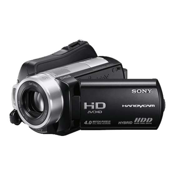
Photo: HDR-SR5
DIGITAL VIDEO CAMERA RECORDER
LEVEL
US Model
Canadian Model
AEP Model
UK Model
E Model
Australian Model
Hong Kong Model
Chinese Model
Korea Model
Tourist Model
Japanese Model
SCHEMATIC DIAGRAMS
PRINTED WIRING BOARDS
REPAIR PARTS LIST
Published by Kohda TEC
RMT-835
2
2007K0800-1
© 2007.11
Advertisement
Table of Contents

Related Manuals for Sony HDR SR5 - AVCHD 4MP 40GB High Definition Hard Disk Drive Camcorder


Summary of Contents for Sony HDR SR5 - AVCHD 4MP 40GB High Definition Hard Disk Drive Camcorder
- Page 1 0 are critical for safety. sécurité. Replace only with part num- Ne les remplacer que par une pièce ber specified. portant le numéro spécifié. DIGITAL VIDEO CAMERA RECORDER 2007K0800-1 HDR-SR5/SR5C/SR5E/SR7/SR7E/SR8/SR8E_L2 © 2007.11 Sony EMCS Co. 9-852-202-32 Published by Kohda TEC...
-
Page 2: Specifications
1080/50i specification information at the time of recording. AC Adaptor (1) Hard disk Mains lead (1) The unique pixel array of Sony’s ClearVid Handycam Station (1) HDR-SR5E: CMOS sensor and image processing Component video cable (1) 40 GB... - Page 3 1080/60i specification information at the time of recording. Software” (1) Hard disk – Picture Motion Browser (Software) The unique pixel array of Sony’s ClearVid HDR-SR5: – Picture Motion Browser Guide CMOS sensor and image processing 40 GB – Handycam Handbook (PDF)
- Page 4 ENGLISH JAPANESE ENGLISH JAPANESE 概略仕様 DCRA-C180 A/V OUT AVCHD HD /MPEG2 SD /JPEG 1 Vp-p 75 A/V OUT 1 Vp-p 75 0.286 Vp-p 75 Dolby Digital2/5.1ch 1 Vp-p 75 327 mV 47 k 1 Vp-p 75 2.2 k 0.286 Vp-p 75 COMPONENT OUT 327 mV 47 k NTSC...
- Page 5 Ver. 1.1 2007.06 Model information table Model SR5C SR5E AEP, UK, CH, Destination US, CND, KR, E, JE US, CND, KR, E, JE, J HK, AUS, E, JE Color system NTSC NTSC NTSC 100G Viewfinder HP jack/MIC jack CM board CM-076 CM-076 CM-076...
- Page 6 CRITIQUES POUR LA SÉCURITÉ DE FONCTIONNEMENT. NE COMPONENTS WITH SONY PARTS WHOSE PART NUMBERS REMPLACER CES COMPOSANTS QUE PAR DES PIÈSES SONY APPEAR AS SHOWN IN THIS MANUAL OR IN SUPPLEMENTS DONT LES NUMÉROS SONT DONNÉS DANS CE MANUEL OU PUBLISHED BY SONY.
- Page 7 ENGLISH ENGLISH JAPANESE JAPANESE ENGLISH ENGLISH JAPANESE JAPANESE 注意 電池の交換は,正しく行わないと破裂する恐れがあり ます。電池を交換する場合には必ず同じ型名の電池 又は同等品と交換してください。 サービス,点検時には次のことにご注意下さい。 1. 注意事項をお守りください。 6. フレキシブルプリント基板の取扱いについて • コテ先温度を270℃前後にして行なって下さい。 サービスのとき特に注意を要する個所については, • 同一パターンに何度もコテ先を当てないで下さい。 キャビネット,シャーシ,部品などにラベルや捺印で (3回以内) 注意事項を表示しています。これらの注意書き及び取 • パターンに力が加わらないよう注意して下さい。 扱説明書等の注意事項を必ずお守り下さい。 7. 無鉛半田について 2. 指定部品のご使用を 無鉛半田を使用している基板には,無鉛(Lead Free)を セットの部品は難燃性や耐電圧など安全上の特性を 持ったものとなっています。従って交換部品は,使用 意味するレッドフリーマークがプリントされています。 (注意:基板サイズによっては,無鉛半田を使用して されていたものと同じ特性の部品を使用して下さい。 特に回路図,部品表に0印で指定されている安全上重要 いてもレッドフリーマークがプリントされて いないものがあります)...
-
Page 8: Service Note
ENGLISH JAPANESE ENGLISH JAPANESE 1. SERVICE NOTE 1-1. POWER SUPPLY DURING REPAIRS In this unit, about 10 seconds after power is supplied to the battery terminal using the regulated power supply (8.4V), the power is shut off so that the unit cannot operate. These following method is available to prevent this. - Page 9 ENGLISH JAPANESE ENGLISH JAPANESE 1-2-3. Self-diagnosis Code Table Self-diagnosis Code Block Detailed Symptom/State Correction Function Code Non-standard battery is used. Use the InfoLITHIUM battery. “Memory Stick Duo” is unformatted. Format the “Memory Stick Duo”. “Memory Stick Duo” is broken. Insert a new “Memory Stick Duo”. Remove the power source.
- Page 10 ENGLISH JAPANESE ENGLISH JAPANESE 1-3. METHOD OF COPING WITH SHIFT LENS ERROR (SR7/SR7E/SR8/SR8E) about 330 msec Note: The length of low section will vary a little depending on the conditions. Fig. 2 Change in output voltage of R5792 on the LD-228 board LD-228 BOARD (SIDE A) VC-504 BOARD (SIDE A) R5721...
- Page 11 ENGLISH JAPANESE ENGLISH JAPANESE 1-3-2. E : 62 : 11 [Shift Lens Overheating (Pitch)] Occurred (SR7/SR7E/SR8/SR8E) Connect by the SeusEX and perform the following process. Order Block Page Address Data Procedure 6BB2 Write the data. 7D46 Write the data. 7D48 Write the data.
- Page 12 ENGLISH JAPANESE ENGLISH JAPANESE 1-3-3. E : 62 : 12 [Shift Lens Overheating (Yaw)] Occurred (SR7/SR7E/SR8/SR8E) Connect by the SeusEX and perform the following process. Order Block Page Address Data Procedure 6BB2 Write the data. 7D47 Write the data. 7D49 Write the data.
-
Page 13: Process After Fixing Flash Error
ENGLISH JAPANESE ENGLISH JAPANESE 1-4. PRECAUTION ON REPLACING THE VC-504 BOARD DESTINATION DATA When you replace to the repairing board, the written destination data of repairing board also might be changed to original setting. Refer to Service Manual ADJ, and perform “DESTINATION DATA WRITE”. USB SERIAL No. - Page 14 ENGLISH JAPANESE ENGLISH JAPANESE 1. SERVICE NOTE 1-1. 修理時の電源供給について 本機では,安定化電源(8.4Vdc)からバッテリ端子に電源を供給した場合,約10秒後にシャットオフし,動作しなくなります。 これを避けるため,下記の方法を用いてください。 方法: DC入力端子を使用する。(ACアダプタ(AC-L200/L200Bなど)を使用する。) 1-2. 自己診断機能 1-2-2.自己診断表示 1-2-1.自己診断機能について 本機の動作に不具合が生じたとき,ビューファインダまたは 本機の動作に不具合が生じたとき,自己診断機能が働き, LCD画面のカウンタ表示部分がアルファベットと数字の4桁 ビューファインダまたはL C D 画面に,どう処置したらよい か判断できる表示を行います。 「自己診断表示」と「サービス 表示になり,3.2Hzで点滅します。この5文字の表示によっ て対応者分類および不具合の生じたブロックの分類,不具合 モード表示」の2つの表示があります。自己診断機能につい ては取扱説明書にも掲載されています。 の詳細コードを示します。 ビューファインダまたはLCD画面 C : 3 1 : 1 1 3.2Hz点滅 対応者分類...
- Page 15 ENGLISH JAPANESE ENGLISH JAPANESE ql wa qh qk w; wa HDR-SR5/SR5C/SR5E/SR7/SR7E/SR8/SR8E_L2...
- Page 16 ENGLISH JAPANESE ENGLISH JAPANESE LD-228 BOARD (SIDE A) VC-504 BOARD (SIDE A) R5721 IC1803 R1846 IC5703 R5737 HDR-SR5/SR5C/SR5E/SR7/SR7E/SR8/SR8E_L2...
- Page 17 ENGLISH JAPANESE ENGLISH JAPANESE 6BB2 データを書き込む。 7D46 データを書き込む。 7D48 データを書き込む。 (注意1) 7D48 データを書き込む。 7D46 データを書き込む。 7D48 データを書き込む。 (注意1) 7D48 データを書き込む。 6BB2 データを書き込む。 順序2〜7を設定している間にシフトレンズが動いたか確認する。もしシフト レンズが動かない場合はレンズブロックを交換する (注意2) 。動く場合は順序 10に進む。 注意 注意 HDR-SR5/SR5C/SR5E/SR7/SR7E/SR8/SR8E_L2 1-10...
- Page 18 ENGLISH JAPANESE ENGLISH JAPANESE 6BB2 データを書き込む。 7D47 データを書き込む。 7D49 データを書き込む。 (注意1) 7D49 データを書き込む。 7D47 データを書き込む。 7D49 データを書き込む。 (注意1) 7D49 データを書き込む。 6BB2 データを書き込む。 順序2〜7を設定している間にシフトレンズが動いたか確認する。もしシフトレ ンズが動かない場合はレンズブロックを交換する (注意2) 。動く場合は順序10 に進む。 注意 注意 Ω 注意 Ω HDR-SR5/SR5C/SR5E/SR7/SR7E/SR8/SR8E_L2 1-11...
- Page 19 ENGLISH JAPANESE ENGLISH JAPANESE 1-4. VC-504基板交換時の注意 仕向けデータ 補修用基板と交換する時,補修用基板に書かれている仕向けデータは元の設定と違っている場合があります。 ADJ編を参照して,「DESTINATION DATA WRITE」を行ってください。 USBシリアルNo. セットは,1台毎に異なる固有のID(USB Serial No.)を書き込んだ後,出荷されています。 新品の補修用基板には,このIDが書き込まれていないので,基板交換後にIDを入力する必要があります。 ADJ編を参照して,「USB SERIAL No. INPUT」を行ってください。 1-5. フラッシュ異常修理後の処置 本機はフラッシュエラー(自己診断コードE:91:01 )が発生した場合,高電圧による異常を防止するために自動的にフラッ シュ充電および発光禁止の設定になります。 フラッシュエラー発生後はエラーの解除を行う必要があります。エラーは,「全履歴データの初期化」を実行することによ り解除できます。 注:「全履歴データの初期化」については,ADJ編(「2-2. サービスモード」の「7. 履歴データ」)を参照してください。 HDR-SR5/SR5C/SR5E/SR7/SR7E/SR8/SR8E_L2 1-12...
- Page 20 (ENGLISH) HDR-SR5 *Factory *Manufacturing year (US Model) 1-6. PRECAUTION ON REPLACING THE CABINET (G) ASSY (HDR-SR5) Serial No. The model display adopts the laser printing method.Therefore, the *Affix the label Part No. Description cabinet (G) assy for replacement differs depending on the A-1317-525-A SERVICE,CABINET (G (SR5)) (U2) destination.
- Page 21 (ENGLISH) HDR-SR5C *Factory *Manufacturing year (US Model) 1-7. PRECAUTION ON REPLACING THE CABINET (G) ASSY (HDR-SR5C) Serial No. The model display adopts the laser printing method.Therefore, the *Affix the label Part No. Description cabinet (G) assy for replacement differs depending on the A-1317-533-A SERVICE, (G (SR5C)) (U2) destination.
- Page 22 (ENGLISH) HDR-SR5E (E, Hong Kong, Australian, Tourist Models) 1-8. PRECAUTION ON REPLACING THE CABINET (G) ASSY (HDR-SR5E) Serial No. The model display adopts the laser printing method.Therefore, the Part No. Description cabinet (G) assy for replacement differs depending on the A-1317-529-A SERVICE, (G (SR5E)) (E34) destination.
- Page 23 (ENGLISH) HDR-SR7 *Manufacturing year (Japanese Model) 1-9. PRECAUTION ON REPLACING THE CABINET (G) ASSY (HDR-SR7) Serial No. *Affix the label The model display adopts the laser printing method.Therefore, the Part No. Description cabinet (G) assy for replacement differs depending on the A-1317-516-A SERVICE, CABINET (G (SR7)) (J) destination.
- Page 24 (ENGLISH) HDR-SR7E (E, Hong Kong, Australian, Tourist Models) 1-10. PRECAUTION ON REPLACING THE CABINET (G) ASSY (HDR-SR7E) Serial No. The model display adopts the laser printing method.Therefore, the Part No. Description cabinet (G) assy for replacement differs depending on the A-1317-521-A SERVICE, (G (SR7E)) (E34) destination.
- Page 25 (ENGLISH) HDR-SR8 *Manufacturing year (Japanese Model) 1-11. PRECAUTION ON REPLACING THE CABINET (G) ASSY (HDR-SR8) Serial No. *Affix the label The model display adopts the laser printing method.Therefore, the Part No. Description cabinet (G) assy for replacement differs depending on the A-1317-534-A SERVICE, CABINET (G (SR8)) (J) destination.
- Page 26 ENGLISH JAPANESE ENGLISH JAPANESE (ENGLISH) HDR-SR8E (E, Hong Kong, Australian, Tourist Models) 1-12. PRECAUTION ON REPLACING THE CABINET (G) ASSY (HDR-SR8E) Serial No. The model display adopts the laser printing method.Therefore, the Part No. Description cabinet (G) assy for replacement differs depending on the A-1317-541-A SERVICE, (G (SR8E)) (E34) destination.
-
Page 27: Note For Repair
2. DISASSEMBLY NOTE FOR REPAIR • Make sure that the flat cable and flexible board are not cracked of bent at the terminal. Cut and remove the part of gilt Do not insert the cable insufficiently nor crookedly. which comes off at the point. (Be careful or some •... -
Page 28: Identifying Parts
2-1. IDENTIFYING PARTS Control Switch Block SR7/SR7E/ Cabinet (G) Assy (PS25500) SR8/SR8E EVF Block ⋅ BL-013 Board Cabinet (L) Section BT Panel Block ⋅ VC-504 Board ⋅ MS-374 Board ⋅ JK-342 Board Bottom Cabinet Lens Section Lens Section Block (SR7/SR7E/SR8/SR8E) (SR5/SR5C/SR5E) ⋅... -
Page 29: Overall Section
HELP HELP 2-2. DISASSEMBLY EXPLODED VIEW HARDWARE LIST 2-2-1. OVERALL SECTION-1 Follow the disassembly in the numerical order given. 1 Cabinet (G) Assy (1-1 to 1-6) 2 HDD (2-1 to 2-3) 3 Bottom Cabinet Block (3-1) 1-2 (#2) (Slide the Jack Cover(G)) 1 Cabinet (G) Assy... -
Page 30: Evf Block
2-2-2. OVERALL SECTION-2 (SR7/SR7E/SR8/SR8E) EXPLODED VIEW HARDWARE LIST Follow the disassembly in the numerical order given. 1 Cabinet (T(255)) (1-1 to 1-6) 2 Cabinet (R) Section (2-1 to 2-3) 3 BT Panel Block (3-1) 4 EVF Block (4-1 to 4-2) 1 Cabinet (T(255)) 4 EVF Block (Open the Shoe Cover) - Page 31 2-2-3. OVERALL SECTION-2 (SR5/SR5C/SR5E) EXPLODED VIEW HARDWARE LIST Follow the disassembly in the numerical order given. 1 Cabinet (T(255)) Assy (1-1 to 1-5) 2 Cabinet (R) Section (2-1 to 2-3) 3 BT Panel Block (3-1) (Open the Shoe Cover) 1-2 (#2) 1 Cabinet (T(255)) Assy 3 BT Panel Block...
-
Page 32: Control Switch Block
2-2-4. OVERALL SECTION-3 EXPLODED VIEW HARDWARE LIST Follow the disassembly in the numerical order given. 1 Control Switch Block (PS25500) (1-1 to 1-2) 2 Cabinet (F) Block (2-1 to 2-2) 1 Control Switch Block (PS25500) 1-1 (#12) 1-2 (#2) SR5/SR5C/SR5E 2-1 (#14) 2 Cabinet (F) Block... - Page 33 2-2-5. CABINET (L) SECTION-1 EXPLODED VIEW HARDWARE LIST Follow the disassembly in the numerical order given. 1 VC-504 Board (1-1 to 1-5) 2 Main Frame Section (2-1 to 2-4) 2-2(#3) (Peel off the Flexible Board) Cabinet (L) Section-2 (See Page 2-8) (#3) 2-1(#14) (SR7/SR7E/...
- Page 34 2-2-6. CABINET (L) SECTION-2 EXPLODED VIEW HARDWARE LIST Follow the disassembly in the numerical order given. 1 JK-342 Board (1-1 to 1-5) 1 JK-342 Board (#2) 1-1(#12) SR7/SR7E/ SR8/SR8E SR7/SR7E/SR8/SR8E HDR-SR5/SR5C/SR5E/SR7/SR7E/SR8/SR8E_L2...
-
Page 35: Lens Section
2-2-7. CABINET (F) BLOCK EXPLODED VIEW HARDWARE LIST Follow the disassembly in the numerical order given. (SR5/SR5C/SR5E) 1 Lens Section (1-1 to 1-2) 2 Lens Barrier Unit (2-1 to 2-2) (SR7/SR7E/SR8/SR8E) 1 Lens Section (1-1 to 1-2) 2 Lens Barrier Unit (2-1 to 2-5) SR5/SR5C/SR5E 1 Lens Section (SR5/SR5C/SR5E) - Page 36 2-2-8. LENS SECTION (SR7/SR7E/SR8/SR8E) EXPLODED VIEW HARDWARE LIST Follow the disassembly in the numerical order given. 1 ST-175 Board (1-1 to 1-3) 2 LD-228 Board (2-1 to 2-4) 3 Flash Unit (FL25500) (3-1 to 3-8) 1 ST-175 Board 1-1(#3) 1-2 (Claw) - 1 7 (Peel off the Flexible Board) 3-7(#23)
-
Page 37: Flash Unit
2-2-9. LENS SECTION (SR5/SR5C/SR5E) EXPLODED VIEW HARDWARE LIST Follow the disassembly in the numerical order given. 1 ST-175 Board (1-1 to 1-3) 2 LD-228 Board (2-1 to 2-4) 3 Flash Unit (FL25500) (3-1 to 3-6) 1 ST-175 Board 1-1(#3) (Peel off the Flexible Board) - 1 7 1-2 (Claw) (#23) - Page 38 2-2-10. CABINET (R) SECTION EXPLODED VIEW HARDWARE LIST Follow the disassembly in the numerical order given. 1 Loud Speaker (1-1 to 1-2) 2 CK-183 Board (2-1 to 2-4) 3 LCD Panel Block (3-1 to 3-4) 3 LCD Panel Block (See Page 2-13) 1 Loud Speaker 1-1 (#8) - 1 8...
- Page 39 2-2-11. LCD PANEL BLOCK EXPLODED VIEW HARDWARE LIST Follow the disassembly in the numerical order given. 1 Hinge Block (1-1 to 1-9) 2 LCD (2-1 to 2-2) 3 PD-324 Board (3-1 to 3-2) HELP 1 Hinge Block HELP (#12) (#2) (Claw) (#8) 3 PD-324 Board...
- Page 40 HELP Sheet attachment positions and procedures of processing the flexible boards/harnesses are shown. SR5/SR5C/SR5E SR7/SR7E/SR8/SR8E Don't put the FPC on the Flexible Board of projection in this point. the Lens Barrier Unit The FPC edge should be in the pocket of Lens Frame (L(253)). Lens Flexible Sheet Set the tape edge to (10mm ×...
- Page 41 THE METHOD OF ATTACHMENT OF FP-537 FLEXIBLE BOARD AND FP-546 FLEXIBLE BOARD 3 Install the flexible clamp in the hinge assy. 1 Fold dotted line parts of the FP-537 flexible board as shown in figure. Fold Flexible clamp Hinge assy Adhesive tape Adhesive tape...
- Page 42 6 Fold dotted line parts of the FP-546 flexible board as shown in figure. Switch Valley fold FP-546 flexible board 7 Install the FP-546 flexible board in the panel hinge cover (C) as shown in figure. 8 Install the panel hinge cover (C) in the hinge assy as shown in figure. FP-537 flexible board Plate of hinge Hijnge assy...
-
Page 43: Block Diagrams
3. BLOCK DIAGRAMS Link Link OVERALL BLOCK DIAGRAM (1/7) OVERALL BLOCK DIAGRAM (6/7) OVERALL BLOCK DIAGRAM (2/7) OVERALL BLOCK DIAGRAM (7/7) OVERALL BLOCK DIAGRAM (3/7) POWER BLOCK DIAGRAM (1/3) OVERALL BLOCK DIAGRAM (4/7) POWER BLOCK DIAGRAM (2/3) OVERALL BLOCK DIAGRAM (5/7) POWER BLOCK DIAGRAM (3/3) HDR-SR5/SR5C/SR5E/SR7/SR7E/SR8/SR8E_L2... - Page 44 Ver. 1.1 2007.06 3. BLOCK DIAGRAMS 3-1. OVERALL BLOCK DIAGRAM (1/7) ( ) : Number in parenthesis ( ) indicates the division number of schematic diagram where the component is located. CM-077 BOARD (SR7/SR7E/SR8/SR8E) VC-504 BOARD (1/6) CN6601 CN1201 LENS BLOCK 4M_DCOUT1-4M_DCOUT6, 4M_DCOUT1-4M_DCOUT6, 4M_DRVOUT1-4M_DRVOUT6,...
- Page 45 3-2. OVERALL BLOCK DIAGRAM (2/7) ( ) : Number in parenthesis ( ) indicates the division number of schematic diagram where the component is located. VC-504 BOARD (2/6) : VIDEO SIGNAL EMC_XDQM[0-3] VIN_C0 - VIN_C7 EMC_DATA [0] - EMC_DATA [31] VIN_Y0 - VIN_Y7 VIN_HD, VIN_VD, VIN_FLD, EMC_ADDR [0] - EMC_ADDR [12],...
- Page 46 3-3. OVERALL BLOCK DIAGRAM (3/7) ( ) : Number in parenthesis ( ) indicates the division number of schematic diagram where the component is located. VC-504 BOARD (3/6) FP-728 BL-013 Q2908 FLEXIBLE BOARD BOARD IC2901_C/PB_OUT (SR7/SR7E/SR8/SR8E) (SR7/SR7E/SR8/SR8E) AA11 BUFFER Q2910 CN3701 CN5901 CN5902...
- Page 47 Ver. 1.1 2007.06 3-4. OVERALL BLOCK DIAGRAM (4/7) ( ) : Number in parenthesis ( ) indicates the division number of schematic diagram where the component is located. FP-722 FLEXIBLE BOARD VC-504 BOARD (4/6) FP-718 FLEXIBLE BOARD (SR7/SR7E/SR8/SR8E) CN1013 CN7181 J7222 CN1022 VIDEO_I/O...
- Page 48 Ver. 1.1 2007.06 3-5. OVERALL BLOCK DIAGRAM (5/7) ( ) : Number in parenthesis ( ) indicates the division number of schematic diagram where the component is located. VC-504 BOARD (5/6) FP-719 FLEXIBLE BOARD CN1021 CN7191 TMDS_DATA2+_1 TMDS DATA2+ TMDS_DATA2_+ TMDS_DATA2-_1 TMDS DATA2- TMDS_DATA2_-...
- Page 49 Ver. 1.1 2007.06 3-6. OVERALL BLOCK DIAGRAM (6/7) ( ) : Number in parenthesis ( ) indicates the division number of schematic diagram where the component is located. CN5305 LD-228 BOARD SHUTTER_XA SHUTTER_XB LENS BLOCK SHUTTER_A SR5/SR5C/SR5E LENS SHUTTER_B IRIS CN5302 BARRIER MOTOR...
- Page 50 Ver. 1.1 2007.06 3-7. OVERALL BLOCK DIAGRAM (7/7) ( ) : Number in parenthesis ( ) indicates the division number of schematic diagram where the component is located. SP901 FP-546 FLEXIBLE SPEAKER S001 BOARD PANEL REVERSE DETECT 1, 2 5, 6 CK-183 BOARD CN6003 CN6001...
- Page 51 3-8. POWER BLOCK DIAGRAM (1/3) ( ) : Number in parenthesis ( ) indicates the division number of schematic diagram where the component is located. FP-721 FLEXIBLE VC-504 BOARD (1/3) BOARD CN1009 F4601 ACV_UNREG ACV_UNREG_CN MT_BL_UNREG J7212 F4602 DC IN BATT/XEXT BATT/XEXT_CN VTR2_UNREG...
- Page 52 3-9. POWER BLOCK DIAGRAM (2/3) ( ) : Number in parenthesis ( ) indicates the division number of schematic diagram where the component is located. FP-727 CK-183 FP-537 PD-324 BOARD VC-504 BOARD (2/3) LCD901 FLEXIBLE BOARD FLEXIBLE BOARD BOARD Q6108, Q6109 CN1006 CN6005 CN6004...
- Page 53 3-10. POWER BLOCK DIAGRAM (3/3) ( ) : Number in parenthesis ( ) indicates the division number of schematic diagram where the component is located. FP-723 LD-228 BOARD VC-504 BOARD (3/3) IC5304 FLEXIBLE SR7/SR7E/SR8/SR8E LENS BLOCK BOARD 2.8V REG (1/4) CN1012 CN5303 CN5301...
- Page 54 Ver. 1.1 2007.06 4. PRINTED WIRING BOARDS AND SCHEMATIC DIAGRAMS 4-1. FRAME SCHEMATIC DIAGRAM 4-1-1. HDR-SR5/SR5C/SR5E LENS BLOCK LEVEL3 LEVEL3 ST-175 BOARD ST-175 BOARD FP-546 FLEXIBLE BOARD LD-228 BOARD (SIDE A) LD-228 BOARD (SIDE B) (SIDE A) (SIDE B) CONTROL SWITCH BLOCK FLASH UNIT...
- Page 55 Ver. 1.1 2007.06 4-1-2. HDR-SR7/SR7E/SR8/SR8E FP-717 FLEXIBLE BOARD CONTROL SWITCH BLOCK (AD11800) LEVEL3 LEVEL3 ST-175 BOARD ST-175 BOARD FP-546 FLEXIBLE BOARD LD-228 BOARD (SIDE A) LD-228 BOARD (SIDE B) (SIDE A) (SIDE B) CONTROL SWITCH BLOCK FLASH UNIT (SB25500) LENS BLOCK (FL25500) CN5202 FP-712...
-
Page 56: Schematic Diagrams
Ver. 1.1 2007.06 4-2. SCHEMATIC DIAGRAMS Link Link FP-721 FLEXIBLE BOARD CK-183 BOARD (CONTROL SWITCH) (REMOTE, DC IN) FP-722 FLEXIBLE BOARD PD-324 BOARD (LCD DRIVE) : SR7/SR7E/SR8/SR8E (HP, MIC JACK) FP-723 FLEXIBLE BOARD JK-342 BOARD (JACK) (LD-VC CONNECTION) FP-724 FLEXIBLE BOARD ST-175 BOARD (FLASH DRIVE) (VC-ST CONNECTION) FP-725 FLEXIBLE BOARD... - Page 57 ENGLISH JAPANESE 4-2. SCHEMATIC DIAGRAMS ENGLISH JAPANESE 4-2. SCHEMATIC DIAGRAMS 4-2. SCHEMATIC DIAGRAMS (ENGLISH) THIS NOTE IS COMMON FOR SCHEMATIC DIAGRAMS (In addition to this, the necessary note is printed in each block) (For schematic diagrams) 1. Connection • All capacitors are in µF unless otherwise noted. pF : µ Pattern box µF.
- Page 58 ENGLISH JAPANESE 4-2. SCHEMATIC DIAGRAMS ENGLISH JAPANESE 4-2. SCHEMATIC DIAGRAMS (JAPANESE) 回路図共通ノート (他に必要なノートは各ブロックに記載してあります) 【回路図ノート】 1. 接続図 ・ケミコン,タンタルを除くコンデンサで,耐圧50V以下のもの パターンボックス はその耐圧を省略。単位はすべてμF(pはpF)。 カラーバーチャート ・チップ抵抗で指示のないものは,1/10W以下。 Pattern box PTB-450 For PTB-450: J-6020-250-A J-6082-200-A kΩ=1000Ω,MΩ=1000kΩ ・チップ部品交換時の注意 For PTB-1450: Small pattern box 取り外した部品は再使用せず,未使用の部品をご使用くださ J-6082-559-A PTB-1450 J-6082-557-A い。 タンタルコンデンサのマイナス側は熱に弱いため注意してくだ...
- Page 59 Schematic diagrams of the CM-076, CM-077, VC-504 and LD-228 boards are not shown. Pages from 4-5 to 4-31 are not shown. HDR-SR5/SR5C/SR5E/SR7/SR7E/SR8/SR8E_L2...
- Page 60 CN6001 REG_GND REG_GND FP-546 S6005 (PANEL OPEN/CLOSE) FLEXIBLE N.C. LND001-LND006 N.C. PANEL_O/C PAGE 4-39 of LEVEL 2 PANEL_REV LND601 PANEL_REV D6005 CH GND D6001 PANEL_NOR/REV PANEL_NOR/REV PANEL_NOR/REV S6001 XBATT_VIEW XBATT_VIEW CN6004 EP_8.5V EP_8.5V KEY_AD2 KEY_AD2 HI_XRESET EP_2.8V RESET EP_2.8V HI_XRESET RESET BL_-V BL_-V...
- Page 61 Ver. 1.1 2007.06 Q6109 MCH6305-TL-E-S LCD POWER DRIVE 10uH L6103 10uH EP_8.5V L6102 EP_4.6V C6124 FB6101 R6133 PANEL_B 10uH 0.01u 100k EP_2.8V L6101 PANEL_G PANEL_R C6103 C6105 C6107 C6110 C6111 C6112 C6116 C6117 REG_GND 2.2u 0.1u R6135 6.3V 220k REG_GND 6.3V 6.3V D6104...
- Page 62 R7301 XD3_CN R7302 LINE_CNT3 SW_GND 13 14 R7303 CTRL3 LINE_CNT2 R7304 LINE_CNT1 CTRL2 COMPONENT CTRL1 FB7305 D3_LNO_PR FB7306 PBPR_GND D3_LNO_PB FB7307 D3_LNO_Y CN7303 1112 Y_GND REG_GND REG_GND D3_LNO_Y D3_LNO_Y CN7301 REG_GND D3_LNO_PB D3_LNO_PB REG_GND REG_GND D7301 D7302 D3_LNO_PR D3_LNO_PR NSAD500H-T1-A REG_GND LINE_CNT1 LIN_CNT1...
- Page 63 • Refer to page 4-3 (English), 4-4 (Japanese) for mark 0. D5202 T5201 CRF02 (TE85R) C5204 R5204 L5201 220p 4700 2.2uH XE_A C5206 XE_A C5203 330V XE_A CHARGING CAPACITOR XE_A 3216 N.C. IC5201 N.C. TPS65552DGQR FLASH CONTROL ST_GND CHARGE CONTROL FLASH UNIT ST_GND (FL25500)
- Page 64 • Refer to page 4-3 (English), 4-4 (Japanese) for mark 0. C7401 D7402 BH7401 (BATTERY HOLDER) D7403 C7402 Note: BT7401 (lithium secondary battery) is not included in the MS-374 complete board. CN7401 BATT_LI_3V SH_GND_A BT7401 (LITHIUM SECONDARY BATTERY) REG_GND MS_BS REG_GND CN7402 MS_DATA1...
- Page 65 RB5901 D5901 NESW007AT-T099 (EVF BACKLIGHT) CN5901 R5901 R5904 LED_K 1608 EP_4.6V EVF_GND EVF_COM EVF_COM EVF_PSIG EVF_PSIG EVF_VG EVF_VG EVF_VR EVF_VR EVF_VB EVF_VB EVF_PCG EVF_PCG EVF_VCK EVF_EN EVF_STB EVF_VCK EVF_EN EVF_VST EVF_VST EVF_STB EVF_REF EVF_REF EVF_DWN EVF_GND EVF_HCK1 EVF_NRW EVF_HCK2 EVF_RGT EVF_HST EVF_HCK1 EVF_GND...
- Page 66 Ver. 1.1 2007.06 HARD DISK DRIVE VC-504 (1/21) CN1004 PAGE 4-7 of LEVEL 3 FP-515 FLEXIBLE BOARD HDD CONNECTION HDR-SR5/SR5C/SR5E/SR7/SR7E/SR8/SR8E_L2 FP-515 4-38...
- Page 67 LND001 LND324 PANEL_B PANEL_B LND002 LND323 PANEL_G PANEL_G LND003 PANEL_R PANEL_R LND322 LND004 REG_GND REG_GND LND321 LND005 REG_GND REG_GND LND320 LND006 LND319 PANEL_HD PANEL_HD LND006 LND007 LND318 PANEL_REV 2nd S/S KEY_AD PANEL_REV LND005 LND008 LND317 S001 EP_4.6V EP_4.6V CK-183 PANEL LND009 LND316 N.C.
- Page 68 CONTROL SWITCH BLOCK (AD11800) 1Pin-6Pin PAGE 4-48 of LEVEL 2 CN7171 DIAL_B DIAL_B REG_GND REG_GND DIAL_A LND001 DIAL_B DIAL_A LND002 LD-228 REG_GND (1/4) LND003 DIAL_A CN5306 LND004 REG_GND PAGE 4-28 S7171 of LEVEL 3 LND005 PON SW MANUAL LND006 REG_GND CHASSIS_GND CHASSIS_GND LND101...
- Page 69 Note : CN7181 is not supplied, but this is included in the FP-718 flexible complete board. CHASSIS_GND LND052 D_DET LND001 D_CTRL1 LND002 D_CTRL2 LND003 D_CTRL3 LND004 LANC_SIG LND005 LANC_DC LND006 LND007 BATT/XEXT KEY_AD3 LND008 (DVD BURN) LND009 ACV_GND LND010 ACV_GND LND011 ACV_GND LND012...
- Page 70 • Refer to page 4-3 (English), 4-4 (Japanese) for mark 0. Note : BH720 is not included in the FP-720 flexible board. Note : CN7191 is not supplied, but this is included in LND001 BATT_UNREG the FP-719 flexible complete board. LND002 BATT_UNREG LND003...
- Page 71 • Refer to page 4-3 (English), 4-4 (Japanese) for mark 0. Note : J7221 and J7222 are not included in Note : J7211 and J7212 are not included in the FP-721 flexible board. the FP-722 flexible board. LND020 LANC_DC J7211 LND012 HP_GND LANC_JACK_IN...
- Page 72 LND001 A_3.3V/A_2.8V A_3.3V/A_2.8V LND145 LND002 D_1.5V LND144 D_1.5V LND003 D_2.8V LND143 D_2.8V LND004 MT_5V LND142 MT_5V LND005 MT_5V LND141 MT_5V LND006 MT_GND MT_GND LND140 LND007 LND139 MT_GND MT_GND LND008 LND138 REG_GND REG_GND LND009 REG_GND LND137 REG_GND LND010 REG_GND LND136 REG_GND LND011 LND135 PNDCK(13.5MHz)
- Page 73 LND001 ST_UNREG LND114 ST_UNREG LND002 ST_UNREG ST_UNREG LND113 ST_UNREG LND003 ST_UNREG LND112 REG_GND(SHOE_GND) LND004 LND111 SHOE_CONT SHOE_CONT LND005 SCHARGE_ON SCHARGE_ON LND110 LANC LANC_SIG XSCHARGE_FULL VC-504 LND006 XSCHARGE_FULL LND109 Active STROBE EXT_STROBE (1/21) ST-175 STROBO_ON STROBO_ON LND007 LND108 Interface Shoe CN1010 CN5202 HOTSHOE_ID2 VC-504...
- Page 74 LND001 REG_GND REG_GND LND126 LND002 S_Y_I/O S_Y_I/O LND125 LND001 LND101 LND003 REG_GND REG_GND LND124 LND002 LND102 S_C_I/O PANEL_NOR/REV LND004 S_C_I/O LND123 LND003 PANEL_NOR/REV LND103 LND005 REG_GND LND122 LND004 LND104 REG_GND XBATT_VIEW XBATT_VIEW LND006 VIDEO_I/O VIDEO_I/O LND121 LND005 LND105 KEY_AD2 KEY_AD2 LND007 REG_GND REG_GND...
- Page 75 LND001 EVF_VDD LND120 SIRCS_SIG LND008 EVF_VDD D_2.8V LND002 LND119 LND007 EVF_GND SIRCS_VDD EVF_GND LND003 EVF_HST LND118 REG_GND LND006 VC-504 EVF_HST (1/21) TALLY_LED_K LND004 EVF_HCK2 LND117 LND005 EVF_HCK2 CN1025 SIRCS_SIG LND005 LND116 TALLY_LED_A LND004 EVF_HCK1 EVF_HCK1 PAGE 4-7 IC7291 RS-770 of LEVEL 3 LND006 EVF_GND LND115...
- Page 76 CHASSIS_GND S001 NIGHT SHOT Dial_B S002 REG_GND 20pin REG_GND S001 Dial_A N.S SW CAMERA CONTROL D002 CHARGE_LED_VDD (CHARGE/STROBE) XCHARGE_LED RV001 (ZOOM) REG_GND D004 XCAM_LED (CAM) MODE_LED_VDD D003 XPHOTO_LED (PHOTO) DIAL_B XACCESS_LED D001 FP-717 ACCESS_LED_VDD DIAL_B (ACCESS) FLEXIBLE ZOOM_VR_AD REG_GND S004 CN7171 PHOTO REG_GND...
-
Page 77: Control Key Block
Ver. 1.1 2007.06 • Refer to page 4-3 (English), 4-4 (Japanese) for mark 0. S7491 S001 BACKLIGHT (ADAPTER DETECT) REG_GND LND001 1PIN REG_GND LND002 ST_GND CK-183 LND023 2PIN LND003 CN6002 adapter detect LND024 PAGE 4-32 LND004 3PIN N.C. of LEVEL 2 N.C. - Page 78 Signal location of the VC-504 and LD-228 boards are not shown. Pages from 4-50 to 4-59 are not shown. HDR-SR5/SR5C/SR5E/SR7/SR7E/SR8/SR8E_L2...
- Page 79 4-2. SCHEMATIC DIAGRAMS 4-2. SCHEMATIC DIAGRAMS 4-3. SIGNAL LOCATION CK-183 BOARD PD-324 BOARD BB_SI (1/1) BB_SI (1/1) PANEL_VR (1/1) (1/1) (1/1) (1/1) C-10 BB_SO (1/1) BB_SO (1/1) PANEL_VST (1/1) B-10 (1/1) (1/1) (1/1) BL_CONT (1/1) (1/1) PANEL_XHD (1/1) (1/1) (1/1) (1/1) PANEL_XSTBY (1/1)
- Page 80 4-2. SCHEMATIC DIAGRAMS 4-2. SCHEMATIC DIAGRAMS JK-342 BOARD AUDIO_L_I/O (1/1) (1/1) AUDIO_R_I/O (1/1) (1/1) D3_LNO_PB (1/1) (1/1) D3_LNO_PR (1/1) (1/1) D3_LNO_Y (1/1) (1/1) LANC_DC (1/1) (1/1) LANC_SIG (1/1) (1/1) LINE_CNT1 (1/1) (1/1) LINE_CNT2 (1/1) (1/1) LINE_CNT3 (1/1) (1/1) MULTI_JACK_AD (1/1) (1/1) S_C_I/O (1/1)
-
Page 81: Printed Wiring Boards
4-4. PRINTED WIRING BOARDS Link Link CK-183 BOARD FP-515 FLEXIBLE BOARD PD-324 BOARD FP-546 FLEXIBLE BOARD FP-717 FLEXIBLE BOARD JK-342 BOARD : SR7/SR7E/SR8/SR8E ST-175 BOARD FP-718 FLEXIBLE BOARD MS-374 BOARD FP-719 FLEXIBLE BOARD BL-013 BOARD : SR7/SR7E/SR8/SR8E FP-729 FLEXIBLE BOARD COMMON NOTE FOR PRINTED WIRING BOARDS HDR-SR5/SR5C/SR5E/SR7/SR7E/SR8/SR8E_L2... - Page 82 4-4. PRINTED WIRING BOARDS 4-4. PRINTED WIRING BOARDS 4-4. PRINTED WIRING BOARDS (ENGLISH) THIS NOTE IS COMMON FOR PRINTED WIRING BOARDS • : Uses unleaded solder. • Chip parts. Transistor Diode • : Circuit board : Flexible board Pattern from the side which enables seeing. : pattern of the rear side (The other layers’...
- Page 83 Printed wiring boards of the CM-076, CM-077, VC-504 and LD-228 board are not shown. Pages from 4-63 to 4-67 are not shown. HDR-SR5/SR5C/SR5E/SR7/SR7E/SR8/SR8E_L2...
- Page 84 CK-183 (2 layers) : Uses unleaded solder. CK-183 BOARD (SIDE A) CK-183 BOARD (SIDE B) EASY R6002 R6001 (FILM ROLL INDEX) DISP/ BATT INFO RESET D6002 D6008 CN6002 D6005 S6005 PANEL OPEN/CLOSE 1-872-818- 1-872-818- HDR-SR5/SR5C/SR5E/SR7/SR7E/SR8/SR8E_L2 CK-183 4-68...
- Page 85 PD-324 (2 layers) : Uses unleaded solder. PD-324 BOARD ( SIDE A ) LD6101 Q6107 R6106 R6143 C6104 R6139 CN6101 R6130 R6144 R6155 L6101 C6127 C6105 Q6110 IC6101 R6129 R6109 C6108 C6109 R6149 FB6101 R6154 C6103 R6152 R6118 R6146 R6117 C6118 C6115 Q6108...
- Page 86 JK-342 (2 layers), ST-175 (2 layers), MS-374 (2 layers) : Uses unleaded solder. JK-342 BOARD (SIDE A) JK-342 BOARD (SIDE B) ST-175 BOARD (SIDE A) ST-175 BOARD (SIDE B) C5205 R5201 FB7307 FB7306 C5201 D7301 R5203 R5202 FB7305 R5210 R7304 D7302 T5201 R7303...
- Page 87 BL-013 (2 layers), FP-515 (2 layers), FP-546 (1 layer) : Uses unleaded solder. FP-546 FLEXIBLE BOARD BL-013 BOARD (SIDE A) BL-013 BOARD (SIDE B) : SR7/SR7E/SR8/SR8E : SR7/SR7E/SR8/SR8E S001 PANEL REVERSE R5904 R5901 DETECT D5902 C5902 C5903 R5902 1-873-217- 1-873-217- FP-515 FLEXIBLE BOARD LND051 LND103...
- Page 88 Ver. 1.1 2007.06 FP-717 (1 layer), FP-718 (2 layers), FP-719 (2 layers), FP-729 (1 layer), : Uses unleaded solder. FP-717 FLEXIBLE BOARD FP-719 FLEXIBLE BOARD : SR7/SR7E/SR8/SR8E LND001 LND002 LND003 LND004 LND005 LND006 1-873-192- 11 MANUAL S7171 1-873-194- 11 CN7191 HDMI Note: CN7191 is not supplied, but this is included...
-
Page 89: Repair Parts List
NOTE 5. REPAIR PARTS LIST NOTE: Characters A to Z of the electrical parts list indicate location of exploded views in which the desired part is shown. EXPLODED VIEWS EXPLODED VIEWS Link Link OVERALL SECTION-1 OVERALL SECTION-2 OVERALL SECTION-3 CABINET (L) SECTION-1 LENS SECTION LENS SECTION CABINET (L) SECTION-2... - Page 90 5. REPAIR PARTS LIST 5. REPAIR PARTS LIST 5. REPAIR PARTS LIST (ENGLISH) NOTE: When indicating parts by reference number, • -XX, -X mean standardized parts, so they may have some differences from please include the board name. the original one. •...
-
Page 91: Exploded Views
5. REPAIR PARTS LIST 5. REPAIR PARTS LIST DISASSEMBLY HARDWARE LIST 5-1. EXPLODED VIEWS 5-1-1. OVERALL SECTION-1 ns: not supplied (Note 1) (Note 2) Overall Section-2 (See Page 5-3) Note 1 : Refer to page 1-13 “Precaution on replacing the cabi- Note 1 : キャビネット (G) 組立の交換時は1-13ページの “キャビネット... - Page 92 5. REPAIR PARTS LIST 5. REPAIR PARTS LIST DISASSEMBLY HARDWARE LIST 5-1-2. OVERALL SECTION-2 SR7/SR7E/SR8/SR8E SR7/SR7E/SR8/SR8E SR5/SR5C/SR5E EVF Block (SR7/SR7E/SR8/SR8E) (See Page 5-12) SR7/SR7E/ SR8/SR8E BT Panel Block (See Page 5-13) Overall Section-3 Cabinet (R) Section (See Page 5-4) (See Page 5-10) Ref.
- Page 93 5. REPAIR PARTS LIST 5. REPAIR PARTS LIST DISASSEMBLY HARDWARE LIST 5-1-3. OVERALL SECTION-3 SR5/SR5C/SR5E Cabinet (F) Block (See Page 5-7) SR7/SR7E/ SR8/SR8E (Note) Cabinet (L) Section-1 (See Page 5-5) Cabinet (F) Block (See Page 5-7) Note: Refer to page 2-1 “Note for disconnec- tion the harness”...
- Page 94 5. REPAIR PARTS LIST 5. REPAIR PARTS LIST DISASSEMBLY HARDWARE LIST 5-1-4. CABINET (L) SECTION-1 ns: not supplied J7211 Cabinet (L) Section-2 (See Page 5-6) J7212 SR7/SR7E/ SR8/SR8E - 5 0 SR7/SR7E/ SR8/SR8E SR5/SR5C/SR5E MIC901 • Refer to page 5-1 for mark 0. Ref.
- Page 95 Ver. 1.1 2007.06 5. REPAIR PARTS LIST 5. REPAIR PARTS LIST DISASSEMBLY HARDWARE LIST 5-1-5. CABINET (L) SECTION-2 ns: not supplied SR7/SR7E/ SR8/SR8E SR7/SR7E/SR8/SR8E J7222 J7221 Ref. No. Part No. Description Ref. No. Part No. Description A-1274-042-A FP-729 FLEXIBLE BOARD, COMPLETE * 213 3-213-060-01 RETAINER, D TERMINAL * 202...
- Page 96 Ver. 1.1 2007.06 5. REPAIR PARTS LIST 5. REPAIR PARTS LIST DISASSEMBLY HARDWARE LIST 5-1-6. CABINET (F) BLOCK ns: not supplied SR5/SR5C/SR5E Lens Section (SR5/SR5C/SR5E) (See Page 5-9) (10mm × 15mm) Lens Section (SR7/SR7E/SR8/SR8E) (See Page 5-8) SR7/SR7E/SR8/SR8E (10mm × 15mm) CAUTION : For the part of 253: TAPE AS (3-079-115-01) or 255: TAPE (A (2/3)) (2-676-475-01), cut NON WOVEN (T0.25) (3-076-631-01) into the desired length and use it.
- Page 97 Ver. 1.1 2007.06 5. REPAIR PARTS LIST 5. REPAIR PARTS LIST DISASSEMBLY HARDWARE LIST 5-1-7. LENS SECTION (SR7/SR7E/SR8/SR8E) ns: not supplied - 1 7 C5206 IC6701 (Note1, 2) - 0 7 (Note3) Note 1: IC6701 is not supplied, but this is included in CMOS block assy.
- Page 98 Ver. 1.1 2007.06 5. REPAIR PARTS LIST 5. REPAIR PARTS LIST DISASSEMBLY HARDWARE LIST 5-1-8. LENS SECTION (SR5/SR5C/SR5E) ns: not supplied - 1 7 C5206 IC6901 (Note1, 2) - 0 7 (Note3) Note 1: IC6901 is not supplied, but this is included in CMOS block assy.
- Page 99 5. REPAIR PARTS LIST 5. REPAIR PARTS LIST DISASSEMBLY HARDWARE LIST 5-1-9. CABINET (R) SECTION ns: not supplied LCD Panel Block SP901 (See Page 5-11) - 1 8 Ref. No. Part No. Description Ref. No. Part No. Description 3-213-049-01 FRAME, SP RETAINER * 407 3-270-566-01 SHEET, WATERPROOF A-1274-036-A CK-183 BOARD, COMPLETE...
- Page 100 5. REPAIR PARTS LIST 5. REPAIR PARTS LIST DISASSEMBLY HARDWARE LIST 5-1-10. LCD PANEL BLOCK ns: not supplied (Note) (Note) (3.3mm × 3.8mm) - 3 2 Note : Be sure to read “HELP” when you install the FP-537 flexible board and FP-546 flexible board.
- Page 101 5. REPAIR PARTS LIST 5. REPAIR PARTS LIST HARDWARE LIST 5-1-11. EVF BLOCK (SR7/SR7E/SR8/SR8E) LCD902 Ref. No. Part No. Description Ref. No. Part No. Description A-1274-035-A BL-013 BOARD, COMPLETE X-2178-733-1 EYE CUP ASSY 2-664-672-01 GUIDE, LAMP * 503 2-638-819-01 CUSHION, LCD * 510 2-668-134-01 PANEL (CF), POLARIZATION * 504...
- Page 102 5. REPAIR PARTS LIST 5. REPAIR PARTS LIST HARDWARE LIST 5-1-12. BT PANEL BLOCK ns: not supplied BH720 - 3 7 BH7401 : BT7401 (BATTERY, LITHIUM SECONDARY) (Note) Board on the mount position. BT7401 (See page 4-70.) (Note) Note: Replace the battery holder (BH7401) together when replacing the lithium battery (BT7401) on MS-374 board.
-
Page 103: Electrical Parts List
BL-013 CK-183 5-2. ELECTRICAL PARTS LIST Ref. No. Part No. Description Ref. No. Part No. Description A-1274-035-A BL-013 BOARD, COMPLETE (SR7/SR7E/SR8/SR8E) ********************** < CAPACITOR > C5901 1-125-777-11 CERAMIC CHIP 0.1uF C5902 1-165-908-11 CERAMIC CHIP < CONNECTOR > * CN5901 1-816-648-51 FFC/FPC CONNECTOR (LIF) 20P * CN5902 1-817-560-71 CONNECTOR, FPC (ZIP) 21P <... - Page 104 FP-515 FP-546 FP-717 FP-718 FP-719 FP-720 FP-721 FP-722 FP-729 JK-342 Ref. No. Part No. Description Ref. No. Part No. Description A-1202-561-A FP-515 FLEXIBLE BOARD, COMPLETE 1-873-195-11 FP-720 FLEXIBLE BOARD ******************************* ******************** (BH720 is not included in the FP-720 flexible board.) <...
- Page 105 JK-342 Ref. No. Part No. Description Ref. No. Part No. Description FB7302 1-400-927-31 BEAD, FERRITE (1005) FB7305 1-400-833-21 SMD EMI FERRITE FB7306 1-400-833-21 SMD EMI FERRITE FB7307 1-400-833-21 SMD EMI FERRITE FB7308 1-400-833-21 SMD EMI FERRITE < VARISTOR > VDR731 1-803-974-11 VARISTOR, CHIP (1608) VDR732 1-803-974-11 VARISTOR, CHIP (1608) VDR734 1-803-974-11 VARISTOR, CHIP (1608) ************************************************************...
- Page 106 MS-374 PD-324 Ref. No. Part No. Description Ref. No. Part No. Description A-1274-037-A MS-374 BOARD, COMPLETE A-1242-019-A PD-324 BOARD, COMPLETE *********************** *********************** (BT7401 (lithium secondary battery) is not included in the MS-374 complete board.) < CAPACITOR > < BATTERY HOLDER > C6101 1-100-581-81 CERAMIC CHIP 0.0047uF 10%...
- Page 107 PD-324 ST-175 Ref. No. Part No. Description Ref. No. Part No. Description Q6112 8-729-054-49 TRANSISTOR UP04401008S0 < TRANSISTOR > Q6113 8-729-054-48 TRANSISTOR UP04601008S0 0*Q5201 6-551-447-01 TRANSISTOR TIG022TS-S-TL-E < RESISTOR > < RESISTOR > R6101 1-218-957-11 RES-CHIP 2.2K 1/16W R6102 1-218-955-11 RES-CHIP 1.5K 1/16W R5201...
-
Page 108: Checking Supplied Accessories
Ver. 1.1 2007.06 • EXCEPT J MODEL to J MODEL Checking supplied accessories. Power cord AC Adaptor Operating Guide 1-790-107-42 (US, CND) (AC-L200/L200B) (HDR-SR5/SR5C/SR7/SR8) 1-823-947-71 (KR) 1-479-285-21 3-210-378-11 (ENGLISH) (US, CND, E, JE) 1-827-826-41 (UK, E: PAL) 3-210-378-21 (FRENCH) (CND) 1-827-945-61 (AUS) 3-210-378-31 (SPANISH) (US, E:NTSC, JE) 1-828-050-31 (JE) - Page 109 Ver. 1.1 2007.06 • J MODEL 付属品 電源コード AC アダプター 取扱説明書 1-828-050-31 (AC-L200/L200B) 3-210-378-01 (日本語) 1-479-285-21 D端子コンポーネント DVD-ROM ハンディカムステーション ビデオケーブル 「エンジョイハンディーカム」 (DCRA-C180) 1-829-414-11 1-821-168-11 3-093-691-01 日本語/英語/韓国語 A/V接続ケーブル USBケーブル 1-823-156-51 1-829-579-41 リチャージャブル バッテリーパック A-1201-665-A ワイヤレスリモコン (RMT-835) 1-479-275-31 CD-ROM「Handycam Application Software」 ハンディカムハンドブック(PDF) (Picture Motion Browser(ソフトウェア), 印刷用の取扱説明書.pdf (ハンディカムハンドブック.pdf)は Picture Motion Browser ガイド, 全ての言語が付属品のCD-ROMに含まれています。...
- Page 110 Ref. No. Part No. Description Ref. No. Part No. Description 1-797-659-11 HDD (MK6008GAH-60GB) (SR7/SR7E) 1-797-821-11 HDD (MK8009GAH-60GB) (SR7/SR7E) 5-1-5. CABINET (L) SECTION-2 5-1-5. CABINET (L) SECTION-2 SR7/SR7E/SR8/SR8E SR7/SR7E/SR8/SR8E J7222 J7222 2007J0800-1 HDR-SR5/SR5C/SR5E/SR7/SR7E/SR8/SR8E_L2 ©2007.10 Sony EMCS Co. 9-852-202-81 Published by Kohda TEC...
- Page 111 & : Points added portion : Points deleted portion Page Before changed After changed 5-1-9. CABINET (R) SECTION 5-1-9. CABINET (R) SECTION 5-10 Ref. No. Part No. Description Ref. No. Part No. Description ––– ––––––––– –––––––––––––––– * 408 3-218-521-01 SHEET, FLEXIBLE ELECTROSTATIC 5-1-10.
- Page 112 5-21 * CN6101 1-785-905-51 FFC/CONNECTOR, FPC (ZIF) 24P * CN6101 1-819-913-71 CONNECTOR, FPC (ZIF) 24P * CN6105 1-785-905-51 FFC/CONNECTOR, FPC (ZIF) 24P * CN6105 1-819-913-71 CONNECTOR, FPC (ZIF) 24P 2007K0800-1 HDR-SR5/SR5C/SR5E/SR7/SR7E/SR8/SR8E_L2 ©2007.11 Sony EMCS Co. 9-852-202-83 Published by Kohda TEC...
- Page 113 HARDWARE LIST (1/4) #1: M1.7 X 2.5 #2: M1.7 X 4.0 #3: M1.7 X 2.5 #4: M1.4 X 2.5 (Tapping) (Black) (Black) (Red) (Dark Silver) 2-635-562-11 2-635-562-31 2-660-401-01 3-348-998-81 #5: M1.7 X 3.5 (Tapping) #6: M1.4 X 1.7 #7: M1.7 X 1.6 #8: M1.7 X 3.5 (Tapping) (Black) (Silver)
- Page 114 HARDWARE LIST (2/4) #21: M1.4 X 3.0 #22: M1.7 X 5.0 (Tapping) #23: M1.7 X 4.0 (Tapping) #24: B1.7 X 5.5 (Tapping) (Black) (Silver) (Black) (Black) 2-662-396-21 3-083-261-01 3-080-204-11 4-679-805-11 #25: M1.7 X 3.0 #26: M1.4 X 2.0 #27: M1.4 X 2.0 #28: M1.4 X 4.0 (Tapping) (Black) (Silver)
- Page 115 HARDWARE LIST (3/4) #41: M3.0 X 8.0 (Tapping) #42: M2.0 X 4.0 (Tapping) #43: M1.7 X 4.0 #44: M1.7 X 3.0 (Tapping) (Silver) (Silver) (Red) (Silver) 3-065-748-01 7-628-253-00 2-660-401-31 3-078-890-61 #45: M1.4 X 2.5 #46: M1.7 X 3.0 #47: M1.4 X 3.0 (Tapping) #48: M1.7 X 2.5 (Silver) (Red)
- Page 116 HARDWARE LIST (4/4) #64: M1.7 X 5.0 (Tapping) #61: M3.0 X 10.0 #62: M2.0 X 3.0 #63: M5.0 X 12.5 (Silver) (Black) (Silver) (Black) 2-666-551-21 7-682-549-09 3-080-202-21 3-060-811-21 12.5 10.0 #65: M1.4 X 3.5 #66: M1.4 X 1.4 #67: M1.4 X 2.0 #68: M1.7 X 4.0 (Silver) (Silver)
- Page 117 About this service manual For the promotion of browse in the PDF format, the “TABLE OF CONTENTS” was eliminated. As an alternative means, use a conven- tional function, "Bookmark". It will help you search/display not all pages but the desired page. In addition, the page layout was changed so that each page is positioned in the center to improve the visibility on the screen.
-
Page 118: Revision History
Reverse 985220234.pdf Revision History S.M. Rev. Ver. Date History Contents issued 2007.05 Official Release — — 2007.06 Revised-1 • Correction of Model information table • Correction of BLOCK DIAGRAMS, SCHEMATIC DIAGRAMS, PRINTED WIRING BOARDS • Correction of EXPLODED VIEWS • Correction of Accessories S.M.
Need help?
Do you have a question about the HDR SR5 - AVCHD 4MP 40GB High Definition Hard Disk Drive Camcorder and is the answer not in the manual?
Questions and answers