Table of Contents
Advertisement
Available languages
Available languages
I CRRFTSMRN1
Operator's
Manual
Snow Thrower
9 Horsepower
Electric Start
Dual Stage
Model 536.887991
CAUTION: Before using this product,
read this manual and follow all of its
Safety Rules and Operating Instructions.
Manual del usario
Quitanieves
9 caballos
de fuerza (hp)
Biet&pico
Arranque
el_ctrico
Modelo 536.887991
PRECAUCI6N:
Antes de usar este producto,
lea este manual y siga todas las reglas de
seguddad e instrucciones de operaci6n.
Sears, Roebuck
and Co., Hoffman
Estates,
IL 60179 U.S.A.
F-O21084L
www.sears.com/craftsman
Advertisement
Table of Contents

Related Manuals for Craftsman 536.887991


Summary of Contents for Craftsman 536.887991
- Page 1 9 caballos de fuerza (hp) Biet&pico Arranque el_ctrico Modelo 536.887991 PRECAUCI6N: Antes de usar este producto, lea este manual y siga todas las reglas de seguddad e instrucciones de operaci6n. Sears, Roebuck and Co., Hoffman Estates, IL 60179 U.S.A. F-O21084L www.sears.com/craftsman...
-
Page 2: Storage Troubleshooting
ON CRAFTSMAN SNOW THROWER For two years from the date of purchase, when this Craftsman Snow thrower is maintained, lubricated, and tuned up according to the operating and maintenance instructions in the owner's manual, Sears will repair, free of charge, any defect in material or workmanship. -
Page 3: Operation
TRAINING Always wear safety glasses or eye shields during operation or while performing an ad- Read this operating and service instruction justment or repair to protect eyes from manual carefully. Be thoroughly familiar foreign objects that may be thrown from the with the controls and the proper use of the snow thrower. -
Page 4: Maintenance
13.Never operate the snow t hrower near en- MAINTENANCE AND STORAGE closures, automobiles, window wells, drop- Check shear bolts and other bolts at fre- offs, and t he like without proper adjustment quent intervals for proper tightness to be ofthe snow d ischarge angle. - Page 5 Drive C lutch Forward ReverseAuger Clutch Auger Collector Engage Push T oEngage Fuel Fuel OilMixture Electric Starter Discharge DOWN Discharge Discharge LEFT Discharge RIGHT Weight Transfer Weight Transfer Transmission Ignition K ey LiftHandle To Depress Pedal Insert ToRun, Engage ToDisengage Pull O ut T o Stop.
- Page 6 CONTENTS OF PARTS BAG (ACTUAL SIZE) 1 - Owner's Manual (not shown) 1 - Packet of Fuel Stabilizer (not shown) 1 - Warranty Card (not shown) Parts,foundintoolboxlocated on beltcover *Non-Assembly PARTS PACKED SEPARATELY IN CARTON (NOT SHOWN FULL SIZE) 2- ignition Keys (Attached to engine in plastic bag) F_)2t084L...
-
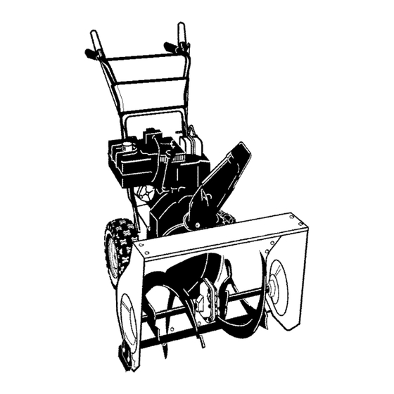
Page 7: Tools Required For Assembly
EF,F,F,F,F,F_.-.][.-] _ _vA I-_] i i_4 Figure 2 shows the snow thrower com- safety glasses or eye shields pletely assembled. ARNING: Always wear while assembling snow References to the right or left hand side thrower. of the snow thrower are from the view- point of the operator's position behind TOOLS REQUIRED... - Page 8 6. Install the fasteners that were re- TO ASSEMBLE THE HANDLE CRANK ASSEMBLY moved in step 4. DO NOT tighten 1. Cut tie holding shift rod to lower until all bolts are in place. handle and move shifter to the first forward gear.
-
Page 9: How To Set The Length Of The Cables
NOTE: If the cables have become dis- connected, connect cables as shown in Figure 7. Traction Drive Cable Auger Drive Cable Figure 7 HOW TO SET THE SKID HEIGHT Your snow thrower is equipped with height for different conditions, see To height adjust skids on the outside of the Adjust Skid Height paragraph in the... - Page 10 KNOW YOUR SNOW THROWER READ THiS OWNER'S MANUAL AND SAFETY RULES BEFORE OPERATING YOUR SNOW THROWER. Compare the illustrations with your SNOW THROWER to familiarize yourself with the location of various controls and adjustments. Save this manual for future reference. Electric Auger (left hand)
- Page 11 The operation ofanysnow thrower can the speed you desire by moving the result i nforeign o bjects b eing thrown speed shifter lever left into the ap- intotheeyes, which canresult inse- propriate notches on the shift lever vere eyedamage. Always w ear s afety plate: glasses oreyeshields w hile operating Speeds 1,2 - Wet, Heavy...
-
Page 12: Before Starting The Engine
2. For ease of maneuverability in light 2. Remove the oil fill cap/dipstick. snow conditions, disconnect the Check the oil. klick pin from the wheel locked 3. If necessary, add oil until the oil position and push into the single reaches the FULL mark on the oil fill wheel drive position (unlocked axle... -
Page 13: To Stop Engine
Fill t hefueltank only withafresh, clean, unleaded regular, unleaded pre- equipped with a three-wire ARNING: The starter is mium, orreformulated automotive gas- power cord and plug and is oline.DONOT useleaded g asoline. designed to operate on 120 volt AC Make sure thatthecontainer youpour household current. -
Page 14: Frozen Starter
6, Push theprimer b utton as speci- button. If the engine fails to start, follow the Cold Start instructions. fied below. Remove finger from primer button between pushes. Do not push if temperature FROZEN STARTER above 50 ° F (10 ° C), If the starter is frozen and will not turn Push two times if temperature engine:... -
Page 15: Snow Throwing Tips
HOW TO REMOVE OBJECTS Release auger drive lever. FROM AUGER Move throttle lever to stop position. Remove (do not turn) ignition key. to remove any item that may Disconnect spark plug wire. ARNING: Do not attempt become lodged in auger Do not place your hands in the au- without taking the following precau* ger or discharge chute. -
Page 16: Service Records
SERVICE RECORDS Fillin dates asyou Before Every Every Every complete r egular Each Each Before SERVICE service. Often Hours Hours Hours Season Storage DATES Chain Lubrication Change Engine Oil Remove Fuel * Adjust after 2 to 4 hours of use. GENERAL RECOMMENDATIONS AFTER EACH USE... -
Page 17: Specifications
PRODUCT SPECIFICATIONS HORSEPOWER 9 HP DISPLACEMENT 19.34cu.in, GASOLINE 4 quarts CAPACITY (unleaded) OIL CAPACITY 5W30 Hexshaff (20 oz capacity) Figure 13 SPARK PLUG: Champion RJ19LIV (Gap .030 in.) or AUGER GEAR BOX equivalent The auger gear box is lubricated at the factory and should not require addition- VALVE CLEARANCE: Intake: .010 In,... -
Page 18: Spark Plug
NOTE: The oil will drain more freely S.A.E. 5W30 motor oil, pouring when the engine is warm. slowly. DO NOT OVERFILL. "To Add Oil" in the Operation Sec- 3. After draining all the oil, reinstall the tion. oil drain plug securely. 4. - Page 19 _.'_o_ V:_ _ I my:_m_ll_,_l i _vA I_ _i i raise the adjustable skids. Tighten nect the spark plug wire and the mounting nuts. See Figure 16. _l=lb ARNING: Always discon- place it where it cannot NOTE: For rocky or uneven surfaces, make contact with spark plug to pre- raise the front of the snow thrower by vent accidental starting when mak-...
-
Page 20: Belt Adjustment
_.'_o_ V:_ _ I my:_m_ll_,_l i _vA I_ _i i BELT ADJUSTMENT 5. Have someone engage auger drive clutch. Check tension on belt (op- Traction Drive Belt posite idler pulley). Belt should de- flect about 1/2 inch (12.5 mm) with The traction drive belt has constant moderate pressure (Figure 18). - Page 21 _.'_o_ V:_ _ I my:_m_ll_,_l i _vA I_ _i i from the engine pulley. Replace Remove the bottom panel. the auger drive belt with an original Bolt Bottom Panel equipment replacement belt avail- able from a Sears service center, 8, Install the new auger drive belt onto the auger drive pulley and onto pulley.
- Page 22 How To Remove plate is properly secured (see The Traction Drive Belt Figure 21). If the snow thrower will not move for- ward, check the traction drive belt for wear or damage. If the traction drive belt is worn or damaged, replace the belt as follows.
-
Page 23: Belt Guide Adjustment
_.'_o_ !:I _ I mI:1 m_[l_,_l i _vA I_ _i i BELT GUIDE ADJUSTMENT "Z" Fitting 1. Remove spark plug wire. 2. Have someone engage auger drive. 3. Measure the distance between the belt guide and belt. The distance should be 1/8 inch (3.175 mm) for guide. -
Page 24: Cable Adjustment
_.'_o_ B_ I my:1m_[l_,_l i_vA I _ _i i TRACTION DRIVE CABLE ADJUSTMENT 1, Run the engine until the fuel tank is 7, Push the bottom of the traction empty and the engine stops. drive cable through the cable ad- 2, Stand the snow thrower up on the justment bracket until the "Z"... -
Page 25: How To Adjust Or Replace The Friction Wheel
_.'_o_ V:_ _ I my:_m_ll_,_l i _vA I_ _i i HOW TO ADJUST OR REPLACE 5. Install the bottom panel (see THE FRICTION WHEEL Figure 28). 6. Tighten the bolts on each side of the bottom panel. How To Check The Friction Wheel Bolt Bottom Panel If the snow thrower will not move for-... - Page 26 _.'_o_ V:_ _ I my:_m_ll_,_l i _vA I_ _i i How To Replace The Friction Wheel If the friction wheel is worn or damaged, the snow thrower will not move forward. The friction wheel must be replaced as follows. 1. Run the engine until the fuel tank is Wheel Bottom Panel empty and the engine stops.
- Page 27 _.'_o_ V:_ _ I my:_m_ll_,_l i _vA I_ _i i 11. Remove the three fasteners that 17. Check the adjustment of the friction hold the friction wheel to the hub wheel. See "How To Adjust The Friction Wheel" in this section. (see Figure 34).
- Page 28 _.'_o_ f:1_ I my:1m_[l_,_l i _vA I_ _i i HOW TO REPLACE 2. Disconnect the spark plug wire. Make sure all moving parts have THE AUGER SHEAR BOLT stopped. The augers are secured to the auger 3. Align the hole in the auger with the shaft with special shear bolts.
-
Page 29: Snow Thrower
If gasoline remains in the use fuel stabilizer supplied with unit tank, fumes may reach an open or purchase Craftsman Fuel Stabi- flame, spark or pilot light from a fur- lizer No. 3550. Add fuel stabilizer to nace, water heater, clothes dryer, any gasoline left in the tank to mini- cigarette, etc. - Page 30 il;Tell:J_]_'_[eZe_ll_[e] TROUBLE CAUSE CORRECTION Difficult starting Defective spark plug. Replace spark plug. Remove fuel from fuel tank. Water or dirt in fuel system, Add fresh fuel. Engine runs erratically Blocked fuel line, empty gas Clean fuel line; check fuel tank, or stale gasoline supply;...
-
Page 31: California & Us Epa Emission Control Warranty Statement
SEARS, ROEBUCK Federal and California Emission Control Systems Limited Warranty Small Off-Road Engines CALIFORNIA & US EPA EMISSION quired maintenance listed in your Owner's Manual, but Sears, Roebuck and Co. will not CONTROL WARRANTY STATEMENT deny warranty solely due to the lack of receipts The U. -
Page 32: Emission Control System Warranty
ershall pay any charges formaking service Sears, Roebuck and Co. according to Subsec- calls and/or fortransporting theproducts to tion 4 below. Any such part repaired or re- and from the place w here the inspection and/ placed under the ECS Warranty shall be orwarranty work i sperformed. - Page 33 EMISSION-RELATED use shall not r educe Sears. Roebuck and Co. PARTS ECS Warranty obligations. INCLUDE THE FOLLOWING: 9.Unapproved add-on ormodified parts m ay 1. Carburetor Assembly and its Internal Com- not b eused t omodify orrepair aSears, Roe- ponents buck a nd Co. engine. Such u se voids this ECS a) Fuel filter Warranty and shall besufficient grounds for...
- Page 34 CRAFTSMAN 9HP SNOW THROWER 536.887991 ENGINE 25-2 25-3 25-2 25-5 olz25- Re£Ddve Page Ref. Auger Housing Page Part No. Description Part No. Description 71060 WASHER 143.039005 ENGINE (762132) 002x97 BOLT, CARRIAGE 1501482 PLATE, ANTI VIBRATION 028x64 RETAINER, PUSH 910828 SCREW...
- Page 35 CRAFTSMAN 9HP SNOW THROWER 536.887991 ELECTRIC STARTER ES100A Key No. Part No. Description 6218 MOTOR, STARTER 6216 SCREW 6217 SCREW 6219 CORD, STARTER F_)21084L...
- Page 36 CRAFTSMAN 9HP SNOW THROWER 536.887991 FRAME \ lO5 lO8_ Re£ Auger Housing 120qo Page Re£ Drive Page Part No. Description Part No. Description 1501055E701 COVER, BOTTOM 71060 WASHER, SPLIT 310169 SCREW 780055 SCREW, TAP 1501226YZ SPRING IDLER, AUGER 165x164 711682...
- Page 37 CRAFTSMAN 9HP SNOW THROWER 536.887991 GEAR CASE _;!i310 Pa_ No, Description Part No. Description CASE, GEAR, RH 73905 KEY, WOODRUFF RING, QUAD CASE, GEAR, LH 53737 910828 SCREW 583126 BEARING, FLANGE 71100 48275 WASHER, FLANGE 330434 SCREW 50684 BEARING, ROLLER...
- Page 38 CRAFTSMAN 9HP SNOW THROWER 536.887991 DRIVE Ref. Shift Yoke Page Ref. Frame _---_ Page R/# f_{Nheel Ref. Whee Page Ref. Wheel Page DR100A F_)21084L...
- Page 39 CRAFTSMAN 9HP SNOW THROWER 536.887991 DRIVE Key No. Pa_ No. Description 1501092 LF AXLE, SWING PLATE YZ 579851 CHAIN, ROLLER #42x19.00 334163 BEARING AND RETAINER, ASSY 579858 WASHER 780055 SCREW, TAP 5/16-18x0.5 1501236 ASSY, HEX SHAFT 579868 CHAIN, ROLLER #36x18.00 LG...
-
Page 40: Discharge Chute
CRAFTSMAN 9HP SNOW THROWER 536.887991 DISCHARGE CHUTE 603 _ CHUTE100B F_)21084L... - Page 41 CRAFTSMAN 9HP SNOW THROWER 536.887991 DISCHARGE CHUTE Key No. Part No. Description 2x100 SCREW, 5/16-18 X.75 71071 WASHER, FLAT 71038 NUT, 5/16-18 NYLOCK 71071 WASHER 1501260 WINGKNOB 3.00 002X97 BOLT, 5/16-18 CARR. 762222 CHUTE ASSEMBLY 2x100 BOLT, 5/16-18Xl.00 CARR. 71071...
-
Page 42: Auger Housing
CRAFTSMAN 9HP SNOW THROWER 536.887991 AUGER HOUSING F_)21084L... - Page 43 CRAFTSMAN 9HP SNOW THROWER 536.887991 AUGER HOUSING Key No. Part No. Description 583146 PULLEY, 4L 8.40 OD. 2001022 KEY, SQUARE 3/16 X 3/4 15X112 NUT, .50-20 HEXWDFLLK 1501158 SPACER, FRICTION PULLEY 582957 YZ RETAINER, BALL BRNG 43846 BEARING, BALL 001X92...
- Page 44 CRAFTSMAN 9HP SNOW THROWER 536.887991 HANDLE 756 725 Refpa%negine _ 764 760 HDLI05A F_)21084L...
- Page 45 CRAFTSMAN 9HP SNOW THROWER 536.887991 HANDLE Key No. Pad No. Description 1501205E701 HANDLE, UPPER LH 1501206E701 HANDLE, UPPER RH 11234 SCREW,_16-18X2+75 71071 WASHER, FLAT 71060 WASHER, SPTLK .31X.58X.08 15X144 NU_ 5/16-16 REGHEX YZ 11261 STOE RED PLASTIC GRIP-HANDLE FINGER 337399...
- Page 46 CRAFTSMAN 9HP SNOW THROWER 536.887991 CHUTE Ref. Handle Assy 8!7_ 852-9 852-5 852-8 ~ 852-13 Ref. Auger Housing Assy _" 852-10 852-11 _ 852-1 852-2 _\\\\ 852-7 852-3 F_)21084L...
- Page 47 CRAFTSMAN 9HP SNOW THROWER 536.887991 CHUTE Key No. Part No. Description 852-1 1501309 YZ ASSEMBLY, YOKE & ROD 852-2 313431 WASHER, CURVED SPRING 852-3 1501067 GEAR, CHUTE ROTATION 9T 852-5 579493 PIN, COTTER 852-6 1501306E701 BRACKET, CHUTE GEAR 852-7 1501293...
- Page 48 CRAFTSMAN 9HP SNOW THROWER 536.887991 SHIFT YOKE SYOKEIOOA Key No. Part No. Description 336702E701 ROD, SHIFT 302628 SCREW, 1/4-20X,75 73826 NUT, 1/4-20 331624 KNOB, SLIP 760564 LEVER, SPRING 302628 SCREW, 1/4-20X,75 73826 NUT, 1/4-20 1501085 YZ ROD ASSY,, SPEED SELECT...
- Page 49 CRAFTSMAN 9HP SNOW THROWER 536.887991 PANEL 771_ PANEL101A Key No. Part No. Description 1501203E549 PANEL 002x99 BOLT, CARRIAGE 71067 WASHER 15X145 NUT 1/4-20 NYLOCK YZ DECALS Part No. Description 48x2034 DECAL DANGER CHUTE - HAND * 48x2036 DECAL DANGER & FOOT...
- Page 50 CRAFTSMAN 9HP SNOW THROWER 536.887991 WHEELS Re£ Drive Page WHL100A Part No. Key No. Description 1501284 YZ SHAFT, AXLE 1501089 SPRKT & HUB 0tx193 SCREW, 1/4-20X2,25 15X145 NUT+ 1/4-20 HEX NYLOCK YZ 1501114 BEARING, AXLE 712120 WASHER, FLAT 1501138 BUSHING, WHEEL 1501022 TIRE &...
-
Page 51: Engine Model Number
CRAFTSMAN 4-CYCLE ENGINE MODEL NUMBER 143.039005 48 _ d_t',.325 370C 900J • F_)21084L... - Page 52 CRAFTSMAN 4-CYCLE ENGINE MODEL NUMBER 143.039005 PART PART DESCRIPTION DESCRIPTION RPM High 3550 to 3850 650128 Screw, 10-24x 1/2" RPM Low 2000 37342 Cylinder Cover Gasket 35385 Cylinder (Incl. 2, 20 & 72) 35376A Cylinder Cover 27652 Dowel Pin (Incl. 71, 75 & 80) 650820 Screw, 1/4-20 x 1/2"...
- Page 53 CRAFTSMAN 4-CYCLE ENGINE MODEL NUMBER 143.039005 149A 35862 Valve Spring Cap 26460 Fuel Line Clamp 27881 Valve Spring 650665 Screw, 1/4-15 x 3/4" 34186A Fuel Tank 32581 Valve Spnng Keeper (incl. 292 & 301) 27896A Valve Cover Gasket 35355 Fuel Cap...
- Page 54 CRAFTSMAN 4-CYCLE ENGINE MODEL NUMBER 143.039005 F_)21084L...
- Page 55 CRAFTSMAN 4-CYCLE ENGINE MODEL NUMBER 143.039005 PART DESCRIPTION 640052 Carburetor (Inc1.184 of Engine Parts List) 631776A Throttle Shaft & Lever Assembly 631970 Throttle Return Spring 631778 Throttle Shutter 650506 Shutter Screw 632112 Choke Shaft & Lever Assembly 632174 Choke Shutter...
- Page 56 CRAFTSMAN 4-CYCLE ENGINE MODEL NUMBER 143.039005 14---,_,"-- F_)21084L...
- Page 57 CRAFTSMAN 4-CYCLE ENGINE MODEL NUMBER 143.039005 PART DESCRIPTION 33329E Electric Starter (110 Volt) 33451 Dust Cover 33842 Retainer Ring 33430 Spring Retainer 33431 Anti-drift Spring 37050 Gear & Nut (IncL 2) 35449 Drive End Cap Ass'y. (Incl. 7) 35450 "O" Ring...
- Page 58 CRAFTSMAN 4-CYCLE ENGINE MODEL NUMBER 143.039005 PART DESCRIPTION 590749 Rewind Starter 590599A Spring Pin (IncL 4) 590600 Washer 590679 Retainer 590601 Washer 590676 Brake Spring 590680 Starter Dog 590412 Dog Spring 590682 Pulley & Rewind Spring Assembly 590750A Starter Housing Assembly 590535 Starter Rope (Length 98"...
- Page 59 LIMITADA DE DOS A_IOS PAPA EL QUITANIEVES CRAFTSMAN Durante dos afios a partir de la fecha de compra, siempre que a esta quitanieves Craftsman se le d6 mantenimiento, lubricaci6n y afinamiento de acuerdo con las instrucciones de operaci6n y mann tenimiento presentadas en el manual del usuario,Sears reparar&, sin cargo alguno, cualquier defec_...
- Page 60 CAPACITACI6N y/o del sol hace que el combustible se expanda. Lea con atenci6n las instrucciones en el Para todos los quitanieves con motores manual de operaci6n y servicio. Familiari- de arranque el6ctrico, use cables de ex- cese completamente con los controles y tensi6n con certificaci6n CSA!UL el uso apropiado del quitanieves.
- Page 61 na/propulsor ytodas las partes m6viles ruedas, juegos dearranque el_ctdco, se encaentren detenidas, yqae todos los etc.). controles est6n desenganchados. Desco- 19. N anca opere elquitanieves sin tener bue- necte elcable d elabujia ymant6ngalo navisibilidad oiluminaci6n. AsegQrese alejado delabujia p ara e vitar unarran- siempre que tiene b uena estabilidad, y...
- Page 62 IMPORTANTE: Muchos de estos simbolos est_n colocados en su quitanieves o estan impresos en los manuales que vienen con el producto. Antes de operar el quitanieves aprenda y comprenda el objetivo de cada simbolo. Simbolos de control y operacibn Despacio R_pido Arranque eldctrico Arranque de motor...
- Page 63 Simbolos de control y operacibn Mezcls de combustible Combustible Aceite y aceite Descarga hacia Descarga hacis Descsrga hscia la Descarga hacia la ABAJO ARRIBA IZQUIERDA DERECHA Transferencia de peso Transferencia de peso Llave de encendido Levante el mango Presione el pedal Insertar para marcha, pars enganchar, para desengsnchar.
- Page 64 CONTENIDO DE LA BOLSA DE PARTES (TAMANO REAL) 1 - Manual det Propietario (no se muestra) 1 - Paquete de estabilizador de combustible (no se muestra) 1 - Tarjeta de garantia (no se muestra) *Las partes que no necesitan ensamblado se encuentran en la caja de herramientas ubicada en la cubierta de la correa.
-
Page 65: Herramientas Necesarias
La Figura 38 muestra el quitanieves gafas de seguridad o protecto* completamente ensamblado. DVERTENCIA: Siempre use res para los ojos mientras La referencia a los lados izquierdo y sambla el quitanieves. derecho del quitanieves se hace desde la posici6n del operador cuando 6ste se HERRAMIENTAS NECESARIAS encuentra detr_s de la unidad. - Page 66 C6MO ENSAMBLAR EL MANGO Y EL CONJUNTO DE LA MANIVELA Conexi6n en "Z" 1, Corte los amarres que sujetan la palanca de cambios al mango inferior y mueva la palanca a la primera velocidad de avance, 2, Corte y deseche el amarre de pl_s- tico que sujeta el conjunto de la ma- nivela.
- Page 67 Si los cables se han desconec- NOTA: tado, con6ctelos como se muestra en la Figura 43. Cable de Cable de propul- propulsi6n si6n de la barrena Figura 43 C(3MO AJUSTAR LOS PATINES DE ALTURA Su quitanieves est& equipado con patines de clones, consulte "Ajuste de los patines de ajuste de altura ubicados en la parle exterior...
- Page 68 CONOZCA SU QUITANIEVES LEA ESTE MANUAL DEL USUARIO Y LAS REGLAS DE SEGURIDAD ANTES DE USAR USAR SU QUITANIEVES, Compare las figuras con su QUITANIEVES para familarizarse con las posiciones de los diversos controles y ajustes, Guarde este manual para referencia futura. Palanca de Palanca de propul- BotCh de arran-...
- Page 69 Laoperaci6n decualquier quitanieves puede ca de cambio de velocidades a ]a ranura ocasionar que objetos extra£Los sean l anza- apropiada de] panel de control de cam- dos con fuerza hacia l os ojos, Iocaal podria bios. resultar enlesiones graves. Use siempre Velocidad 1, 2 - Nieve mojada, pesada gafas deseguridad o protectores...
-
Page 70: Antesde Encender El Motor
Tapa/varilla indicadora nivel de acute Pasador klic_._ Posici6n de desenganche racclon en .____i una sola t_P"_ Uueda Figura 47 NOTA: El nivel del aceite deber& estar entre la marca FULL (lleno) y la marca NOTA: AsegQrese de que el pasador klick est6 en la posici6n de tracci6n de una sola ADD (agregar) Figura 48... -
Page 71: Parada Del Motor
Llene e ltanque solamente con gasolina fres- ca,limpia, regular sinplomo, s_per sinplo- arranque est& equipado con un DVERTENCIA: El motor de moo gasolina automotor reformulada. cable de alimentacibn y enchu- use gasolina con plomo. Aseg_rese deque fe trifilar, diseSados para funcionar con el recipiente que contiene la gasolina a utili- corriente dom_stice de 120 voltios CA. - Page 72 tomacorrientes trifilar de120 voltios CA, C6mo hater arrancarun motorcaliente conectado atierra. Siesta arrancando un motor caliente des- 6. Empuje el pu6s de haberlo apagado por un periodo botbn cebador de la manera corto, deje la palanca del estrangulador en la indicada a continuaci6n.
- Page 73 C6MO RETIRAR OBJETOS Mueva la palanca de control de acelera- ATASCADOS DE LA BARRENA ci6n a la posici6n "parar". Retire (sin girar) la Ilave de ignici6n. car ning_n objeto etascado en Desconecte el cable de la bujia. ADVERTENCIA: No intente sa- le barrena sin tomar las precau- No coloque las manes en la barrena o clones siguientes.
-
Page 74: Recomendaciones Generales
hVi r:ll i I _ 1i hVlll_1i tie] REGISTROSDE SERVIClO Anate las fechas a me- Antes Cada Cada Cada Cada Antes FECHA didaque completeel de ca- A me- tempo- servicio da uso nudo horas horas horas rada guardar SERVICIO ............Lubricaci6n de la cade- Cambiar el aceite del motor... -
Page 75: Especificaciones
hVff:1_ i I _ _i hVAIl_ _i tie] ESPECIFICACIONES PRECAUCI(_N: No permita que la grasa entre en contacto con la rueda de friccibn ni con la placa del disco de propulsibn. CABALLOS 9 HP FUERZA 6. Instale el panel inferior. ;ILiNDRADA 19.34cuJn CAPACiDAD... -
Page 76: Cambio De Aceite
hVff:_f_ i I _ _i hVAIl_ _i tie] CAMBIO DE ACEITE NOTA: El aceite fluira mejor si el motor es- t_ caliente, Una vez que haya sacado todo el aceite, 1. Coloque el quitanieves de manera tal que coloque nuevamente el tap6n de drenaje el tap6n de drenaje del aceite sea el pun- en su lugar y apri6telo para que quede... - Page 77 i_]_I_[*'_III_ 4. Afloje las tuercas de montaje que sujetan los patines de ajuste de altura. Para bajar ]a parte delantera del quitanieves, suba el arranque accidental del mo- ADVERTENCIA: Para prevenir los patines. Apriete las tuercas de mon- tor, siempre desconecte el ca- taje.
- Page 78 i_]_I_[_'_III_ AJUSTE DE LAS CORREAS beda ceder media pulgada (12,5 ram) con presi6n moderada Correa de propulsibn (Figura 54). Puede que tenga que La correa de propulsi6n tiene una mover la polea guia m_s de una presi6n de resorte constante y no re- vez para conseguir la tensi6n co- rrecta.
- Page 79 i_]_I_[_'_III_ 2, Afloje los pernos a cada lade del barrena y de la polea del motor, panel inferior (Figura 55), Instale una correa de propulsibn 3, Quite el panel inferior. de la barrena nueva original de f_- brica que haya comprado en un Perno Panel inferior...
- Page 80 i_]_I_[_'_III_ Cbmo desmontar la correa de sujeta (Figura 57). propulsibn SI el quitanieves no se mueve hacia adelante, asegerese de que la correa de propulsi6n no est6 excesivamente desgastada o daSada. SIIo est,, reempl_cela de la siguiente manera. 1. Desconecte el cable de la bujia. 2.
- Page 81 i_]_I_[_'_III_ AJUSTES DE LA CORREA GUIA Accesono °Z" 1. Quite el cable de la bujia. 2. Pida a alguien que ponga el propul- sor de la barrena. 3. Mida la distancia entre la guia de la correa y la correa. La distancia de- be ser de 1/8 de pulgada (3,175 mm) para la guia.
- Page 82 i_]_I_[_'_III_ AJUSTES DEL CABLE DE PROPULSI6N 1, Deje el motor en marcha hasta que 7, Meta la parte inferior del cable de el tanque de combustible quede va- propulsibn por el soporte de ajus- cioy el motor se pare, te del cable hasta que pueda sacar 2, Levante el quitanieves con el extre- el gancho "Z".
- Page 83 i_]_I]-'II_ C6MO AJUSTAR O REEMPLAZAR LA RUEDA DE FRICCION Cbmo revisar la rueda de friccibn 12 y 13 pulgs. 4-1/8" 16 pulgs. 4-5!16" Si el quitanieves no avanza, revise la Si la rueda de fricci6n no est_ en la cerrea de propulsi6n por tracci6n, el ca- posici6n correcta, ajQstela de acuer- ble de propulsi6n o la rueda de fricci6n.
- Page 84 i_]_I_[_'_III_ Cbmo reemplazar la rueda de fricciOn Si la rueda de fricciOn est_ gastada o da5ada, el quitanieves no avanza. rueda de fricciOn se debe cambiar de la siguiente manera. Panel inferior Llanta 1. Deje el motor en marcha hasta que el tanque de combustible quede va- Figura 67 cioy el motor se pare.
- Page 85 i_]_I_[_'_III_ 12. Quite la rueda de friccibn del cu* 18. AsegOrese de que la rueda de fric- bo. Deslice la rueda de friccibn ci6n y la placa del propulsor de dis- fuera del eje hexagonal. co no tienen ni grasa ni aceite. 13.
-
Page 86: Ajuste Del Carburador
i_]_I__,III_ C6MO REEMPLAZAR LOS PERNOS Desconecte el cable de la bujia. Aseg_- rese de que todas las piezas m6viles se SEGURIDAD DE LA BARRENA hayan detenido. Las barrenas estan sujetas al eje de la ba- 3. Alinee el agujero de la barrena con el rrena con pemos de seguridad especiales. -
Page 87: Otras Indicaciones
Craftsman de una caldera, calentador NQm. 3550. Ahada el estabilizador agua, secadora de ropa, cigarrillo, de combustible a cualquier cantidad etc. - Page 88 PROBLEMA CAUSA CORRECCION Dificultad de Bujia defectuosa. Reemplace la bujia defectuosa. arranque Agua o suciedad en el sistema Saque el combustible del tanque. de combustible. ASada combustible fresco. El motor funeiona Linea de combustible bloqueada, Limpie la linea de combustible; err_ticamente falta de combustible o mezcla de...
- Page 89 SEARS, ROEBUCK Garantia limitada de cumplimiento con el Sistema Federal de control de emisiones y con el sistema de control de emisiones del Estado de California Motores peque_os para vehiculos todo terreno CONTROL DE EMISIONES DE S|STEMA PARA EL CONTROL DE CALIFORNIA Y DE LA AGENClA DE EM|SIONES DEL FABRICANTE -...
-
Page 90: Nota Importante
Sears, Roebuck and Co., o a Sears, Roebuck A. CAMPO DE APLICACION: Esta garantfa and Co., a11400-473-7247 (llamada gratui- deber& aplicarse a los motores pequefios para ta en E.U.A.). vehiculos torio terreno modelo 1995 y morie- los tie afios posteriores en California (para otroe estados, motores modelo 1997 y mode- NOTA IMPORTANTE... - Page 91 Garantia SCE deber& garantizarse por e l r esto aprobada por S ears, Roebuck and Co. p ara del P eriodo delamisma, utilizarse eneldesempeSo decualquier man- tenimiento o cambio delaGarantia SCE, la 3.Cualquier parte g arantizada yrelacionada coal seproporcionar_ sin cargo alguno para e l con emisiones que seespecifique para c am-...
- Page 92 Get it fixed, at your home or ours! Your Home For repair in your home of all major brand apphances, lawn and garden equipment, or heating and coohng systems, no matter who made it, no matter who sold it! For the replacement parts, accessones owner s manuals that you need to do-it-yourself For Sears professional installation of home apphances...
Need help?
Do you have a question about the 536.887991 and is the answer not in the manual?
Questions and answers