Table of Contents
Advertisement
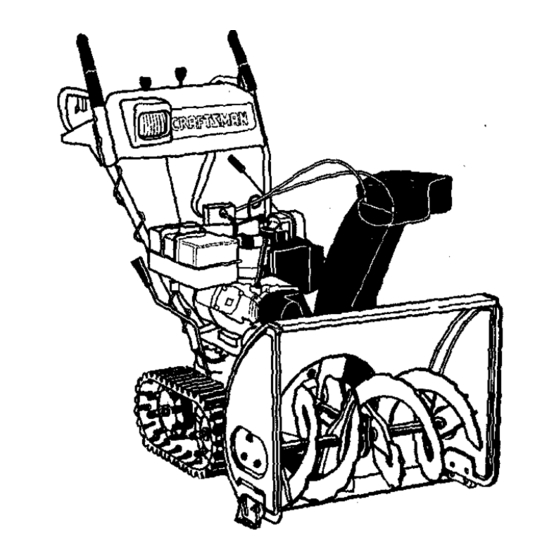
Owner's Manual
9 Horse Power
28" Two-Stage Track Drive
Snow Thrower
Model No.
247.888550
CAUTION: Before
using this product,
read this manual and
follow all safety rules
and operating
instructions.
•
Safety
•
Assembly
•
Operation
•
Service
•
Maintenance
•
Espafiol
Sears, Roebuck And Co., Hoffman Estates, IL 60179, U.S.A.
Visit our Sears website: www.sears.condcraftsman
FormNo.770-10051C
PdntedJnU.S.A.
(6/99)
Advertisement
Table of Contents

Related Manuals for Craftsman 247.888550


Summary of Contents for Craftsman 247.888550
- Page 1 Owner's Manual 9 Horse Power 28" Two-Stage Track Drive Snow Thrower Model No. 247.888550 CAUTION: Before • Safety using this product, • Assembly read this manual and • Operation Service follow all safety rules • • Maintenance and operating instructions. Espafiol •...
- Page 2 Sears will repair, free of charge, any defect in material and workmanship. If this Craftsman snow thrower is used for commercial or rental purposes, this warranty applies for only 30 days from the date of purchase.
- Page 3 This symbol points out important safety instructions which, ifnot followed, could endanger the personal safety and/or propertyof yourself and others. Read and follow all instructions in this manual before attempting to operate your snow thrower. Failure to complywith these instructionsmay resultin personal injury.When you see this symbol--heed its warning.
- Page 4 Use only attachments and accessories (such as wheel weights, counter weights, cabs, etc.) approved Following are representationsof some of the safety labels on your Craftsman snowthrower.Please follow the instructionon these labels and maintain safety while using or servicingthe equipment. ADANGER...
- Page 5 Lay the hardware pieces from the hardware pack on top of the figure here and you will have automatically soded these aCCording to the steps of the assembly procedure described later. (Only one unit of each hardware has been shown per group. The number in parenthesis indicates the total number of the hardware needed in that group.) Lock Washer (4) Hex Bolt (6)
- Page 6 Rear Chute Handte , Left Panel Handles Shift Chute Electric Crank Start Cord Figure I c. Electric Start Cord iMPORTANT: This unitis shippedwith engine oil, but d. Two-Piece Chute Crank Assembly without gasoline, in the engine. After assembly, see e. Shift Rod OPERATION section of this manLJal for fuel selection Hardware Pack and fill-up.
- Page 7 Secure b ottom hole onthehandle t othesnow • Attach handle panel to the handle with two thrower using 5/16x .75" hexboltandlock carriage bolts, cupped washers (cupped side washer from the hardware pack (groupA on againstthe handle panel) and hex nutson each page 5 ).
- Page 8 Insert h ex Place the other 3/8 ID flat washer (from the boltthroughthe upper chute crank same groupof hardware) on the end of the chute bracket, handle panel support, and upper left crank and inserthairpin clip intoeye hole at the handle.
- Page 9 Tighten all loose hardware on the handle WARNING: There must not be any tension on either clutchcable with the driveor auger assembly in the followingorder-- firstthe hex boltsat the bottomof the handle, then the clutchgrip in the disengaged (up) position. carriage bolts and lastlythe hex boltson the rear These clutchesare a safety feature.
- Page 10 Attaching Turn Triggers hardware pack. Make sure to routethe cable tie over the drive cable. See Figure 14. Make sure that the right hand triggercable is routed in front of the traction drive cable. • Feed thetriggercable up through the outersideof the slotinthe handlepanel.
- Page 11 NOTE: Cables are out of adjustment if augers Final Adjustments continueto turn when auger clutchis released and/or machine continuesto run when drive clutchis Adjusting Auger Control released. For more details, refer to the Service and • To check the adjustment of the auger control, Adjustment section.
- Page 12 Knowing Your Snow Thrower Read this owner's manual and safety rules before operating your snow thrower. Compare with your snow thrower to familiarize yourselfwith the location of various controls and adjustments.Save this manual for future reference. The operation of any snow thrower can resultin foreign objectsbeing thrown intothe eyes, which can resultin severe eye damage.
- Page 13 Weight Transfer Lever Operating Controls (See Figure 17.) The weighttransfer lever is locatedon the rightside of the snow thrower and is used to select the positionof Chute Crank the housingand the method oftrack operation. See Figure 18. Move the lever to the right,then forward or The chute crank is located on the left side of the snow backward to one of the three positions.
- Page 14 Before Starting Engine Never use engine or carburetor cleaner products in the fuel tank or permanent damage may occur. Fill Gas To Start Engine WARNING: Gasoline isflammableand cau- & & tionmustbe used when handling or storingit. WARNING: Be sure no one other than the operator is standingnear the snow Do not fillfuel tank whilethe snow thrower is throwerwhile starting or operating.
- Page 15 ColdStart Operate the engine at full throttle (FAST) when throwing snow. NOTE: ff the unit shows any sign of motion (drive or Warm Start augers) with the clutch grips disengaged, shut the engine off immediately. Readjust as instructedin the If restarting a warm engine after a shut down, "FinalAdjustments"section on page 11.
- Page 16 Use slowerspeeds untilyou are familiar with the • After the area is cleared, stop the snow thrower operation of the snow thrower. following instructionsgiven below. Squeeze the traction driveclutchgrip againstthe Operating Tips right handle and the snow thrower will move. Release it and the drive motionwill stop.
- Page 17 General Recommendations • All adjustments in the Service and Adjustments section of this manual should be checked at Always observe safety rules when performing least once each season. any maintenance. • Follow the maintenance schedule given below. The warranty on this snow thrower does not Periodically check all fasteners and make sure cover itemsthat have been subjected to these are tight.
- Page 18 Lubrication Bearings For a view of the lubricationpoints on the snow Once a season lubricatethe auger bearingsand thrower, see Figure 20. the bearingson the side of the frame with light oil. See lubricationchart below. Sprocket Shaft Check V-belts • Lubricatethe sprocketshaft with grease at least Follow instructionsbelow to check the conditionof oncea seasonor after every25 hoursof operation.
- Page 19 • Drain oil while engine is warm. Remove oil drain Engine Maintenance cap located at the bottomof the recoil starter of Engine Oil the engine. Catch oil in a suitable container. • When engine is drainedof all oil, replace drain Only use high quality detergent oil rated with API plug securely.
- Page 20 WARNING: Always stop the engine, dis- NOTE: ff you placed plastic under the gas cap, be certain to remove it, connect spark plug wireand move it away from the spark plug before performingany Augers adjustmentsor repairs, The augers are secured to the spiral shaft with two Never attempt to clean the chute or make shear boltsand hex lock nuts.
- Page 21 Auger Drive Belts • Disconnectthe chute crank at the chute Shift Chute Distance Lever Control assembly by removing the cotter pin and the flat washer. Drive Auger Clutch • Remove the plasticbelt cover on the frontof the engine by removingtwoself-tapping screws. See Figure 25, Upper Self-Tapping...
- Page 22 • Back out the stop bolt untilthe supportbracket drops on the auger pulley, See Figure 28. • Slip belt between friction wheel and friction disc Drive Belt plate and remove the belt. See Figure 28. • Reassemble with new drive belt. NOTE: The supportbracket must rest on thestop bolt after thenew belt has been assembled.
- Page 23 • Reassemble thenew friction wheel r ubber to Carburetor thefriction wheel assembly tightening thesix screws inrotation a ndwithequal WARNING: If any adjustmentsare made to f orce. • Positionthe frictionwheel assembly up onto the engine whilethe engine is running(e.g. carburetor), keep clear of all movingparts. the pin of the shift rod assembly and slide the Be careful of heated surfaces and muffler.
- Page 24 & If your snow thrower is leftunused for 30 days or WARNING: Drain fuel into approved longer, it needs to be prepared for storage. Also, at containeroutdoors,away from any open the end of the snow season, you should follow the flame.
- Page 25 Problem Possible Cause Corrective Action Shift lever not l ocking 1, Shiftrodoutofadjustment 1. Remove washer and pin. Turn ferrule intothesixth speed clockwiseone turn and reinstall, Engine failstostart 1. Fuel tank empty, or stale fuel 1. Filltank with clean, fresh gasoline. 2.
- Page 26 SEARS CRAFTSMAN 9.0 H.P. SNOW THROWER MODEL 247.888550...
- Page 27 SEARS CRAFTSMAN 9.0 H.P. SNOW THROWER MODEL 247.888550 Part No. Part No. Description Description Qty, Qty. 629-0058 736-0509 Harness for Headlight Special Washer 684-0008A- 737-0133 Grease Shift Arm Assembly 0637 746-0896 Chute DeflectorControlCable 684-0053 Chute Crank Assembly 746-0901 Chute Deflector Cable w/Clip...
- Page 28 SEARS CRAFTSMAN 9.0 H.P. SNOW THROWER MODEL 247.888550...
- Page 29 SEARS CRAFTSMAN 9.0 H.P. SNOW THROWER MODEL 247.888550 Part No. Part No. Qty. Qty. Description Description 611-0053 719-0295A Track Housing Axle Assembly 725-0157 Cable Tie 618-0043 Dogg Assembly:RH 618-0044 732-0209 Dogg Assembly:LH Extension Spring 732-0264 618-0169 Extension Spring Shift Assembly: Track Dnve...
- Page 30 SEARS CRAFTSMAN 9.0 H.P. SNOW THROWER MODEL 247.888550 ® ®...
- Page 31 SEARS CRAFTSMAN 9.0 H.P. SNOW THROWER MODEL 247.888550 Pad No. PartNo. Description Qty. No. Description Qty. 750-0547 631-0032 Wheel Assembly Idler Spacer 684-0009 750-0909 Rod Track Pivot Spacer 684-0024 750-0995 Axle Assembly Spacer 684-0038 784-5639-048_ Plate-Track Side Handle Assembly 710-0157...
- Page 32 SEARS CRAFTSMAN 9.0 H.P. SNOW THROWER MODEL 247.888550 NOTE: For painted parts, please refer to the list of color codes below. Please add the applicable color code, wherever needed, to the part number to order a replacement part. For instance, if a part,...
- Page 33 SEARS CRAFTSMAN 9.0 H.R SNOW THROWER MODEL 247.888550 Part No. Pad No. Description Qty. Description Qty. 05931 ExtensionSpdng Bearing Housing 732-0611 LockWasher 5/16 605-5192A SpiralAssembly 736-0119 LookWasher 3/8 605-5193A SpiralAssembly 736-0169 Wave Washer 618-0121 Auger Gear Assembly 736-0174 FlatWasher .76 I.D. x 1,49O.D.
- Page 34 SEARS CRAFTSMAN 9.0 H.P. SNOW THROWER MODEL 247.888550 Pad No. Description Qty. Pad No. Description Qt_, Bracket 05896A 736-0505 Flat Washer Extension Cord 629-0071 748-0234 Shoulder Spacer Screw 710-0627 748-0360 Adapter Pulley Screw 710-1245 V-Belt 754-0346 Screw 710-0230 754-0430 V-Belt Matched...
- Page 35 Craftsman Engine Model No. 143.999005 for Craftsman Snow Thrower Model 247.888550 CARBURETOR Part Description Qty. 640052 Carburetor (Incl. 184 of Engine Parts List) 631776A Throttle Shaft & Lever Ass'y 631970 Throttle Return Spring 631778 Throttle Shutter 650506 Shutter Screw 632112 Choke Shaft &...
- Page 36 Craftsman Engine Model No. 143.999005 for Craftsman Snow Thrower Model 247.888550 >300 !_120 ,308 'q_325 224. "275 185. 370C 200 x...
- Page 37 Craftsman Engine Model No. 143.999005 for Craftsman Snow Thrower Model 247.888550 Part Part Description Qty. Description Qty. 611093 Flywheel (W/Ring Gear) 35385 Cylinder 650880 BellevilleWasher 27652 Dowel Pin 650881 650820 Screw Flywheel Nut 35135 Solid State Ignition Oil Drain Extension...
- Page 38 Craftsman Engine Model No. 143.999005 for Craftsman Snow Thrower Model 247.888550 Table continued from previous page Part Part Description Description Qty. Qty, 35438 Choke Knob 323B 611118 Terminal 29443 28820 Screw Wire Clip 650378 35392 Screw, Torx Starter Plug 35593...
- Page 39 Craftsman Engine Model No. '143.999005 for Craftsman Snow Thrower Model 247.888550 Recoil Starter Description 590733 Rewind Starter 590599A Spring Pin (Incl. 4) 590600 Washer Retainer 590696 590601 Washer 590697 Brake Spring 590698 Starter Dog 590699 Dog Spring 590709 Pulley & Rewind SpringAss'y 590734 Starter Housing Ass'y.
- Page 40 Date Comments...
- Page 41 In U.S.A. or Canada for in-home major brand repair service: Call 24 hours a day, 7 days a week (1-800-469-4663) 1-800-4-MY-HOME Para pedir servicio de reparaci6n a domiciliio m 1-800-676-5811 Au Canada pour tout le service ou les pi_ces -- 1-800-469-4663 For the repair or replacement parts you need: Call 6 a.m.
Need help?
Do you have a question about the 247.888550 and is the answer not in the manual?
Questions and answers