Dell Force10 C150 Manual
Installing and maintaining the c150 system
Hide thumbs
Also See for Force10 C150:
- Manual (57 pages) ,
- Quick start manual (33 pages) ,
- Configuration manual (1262 pages)
Table of Contents
Advertisement
Quick Links
Download this manual
See also:
Configuration Manual
Advertisement
Table of Contents

Related Manuals for Dell Force10 C150


Summary of Contents for Dell Force10 C150
- Page 1 Installing and Maintaining the C150 System...
- Page 2 © 2010 Dell Force10. All rights reserved. Reproduction of these materials in any manner whatsoever without the written permission of Dell Inc. is strictly forbidden. Trademarks used in this text: Dell™, the DELL logo, Dell Precision™, OptiPlex™, Latitude™, PowerEdge™, PowerVault™, ®...
-
Page 3: Table Of Contents
Contents 1 About this Guide Information Symbols and Warnings ........7 Related Documents. - Page 4 8 Installing DC Power Entry Modules Recommended Normal Operating Conditions ......29 Redundancy .
- Page 5 Contacting Technical Support The iSupport Website ..........61 Accessing iSupport Services .
- Page 6 Contents...
-
Page 7: About This Guide
About this Guide This guide provides site preparation recommendations and instructions for installing the Dell Force10 C150 chassis, fan tray, power supply units (PSUs), route processor modules (RPMs), and line cards. The C150 system is packaged with all of the necessary components, including slot blanks for RPMs, power supplies, and line cards. -
Page 8: Related Documents
WARNING: Building Supply Notice for DC Power Supply Use: An external disconnect must be provided and be easily accessible. Dell Force10 recommends the use of a 60A circuit breaker. ATTENTION: Un interrupteur externe doit être fournis et doit être facilement accessible. Dell Force10 recommande l'utilisation d'un disjoncteur de 60Ampères. -
Page 9: Overview
Overview The C150 is a high performance switch/router. This 6-slot system contains two slots for Route Processor Modules (RPMs) and four slots for line cards (Figure 2-1). Figure 2-1. C150 Chassis (Front View) Front Mount Bracket 48-Port 1G Line Card 8-Port 10G Fiber Line Card Fan Tray Route Processor... -
Page 10: C150 System Installation Process Overview
C150 System Installation Process Overview The Dell Force10 recommended installation process is summarized below. Step Task Relevant Section in the Manual Prepare the site. Site Selection Criteria on page 11 Unpack the chassis and components. Shipping and Storing Components on page 12 Install the chassis in a rack. -
Page 11: Preparing The Site
Preparing the Site Site Selection Criteria Before beginning the installation process, make sure that the area where you intend to install your C150 meets the following safety requirements: • It is in a restricted access area. • It is in a dry, clean, well-ventilated, temperature-controlled room, that is away from heat sources such as hot air vents or direct sunlight. -
Page 12: Power Requirements
Save the protective packaging in which your line cards, RPMs, power supplies, and fan tray arrived. The packaging can be used in case you experience trouble with a component and must return it to Dell Force10. Place the components in their original protective shipping packaging and original shipping position. -
Page 13: Installing The C150 Chassis
Installing the C150 Chassis Safety Considerations NOTE: Use an equipment lift or pallet jack when lifting or moving the chassis. Install the chassis into the rack before inserting chassis components. Lift the C150 chassis only from the bottom. Lifting by the chassis shelves or power supply openings might damage the chassis. -
Page 14: Installing The Chassis Into An Equipment Rack
Step Task Dell Force10 recommends that you install a equipment rack bar. This bar enables you to easily position the chassis into the rack and stabilizes the chassis. • Orient the equipment rack bar at the desired location in the rack, with the arrows pointing up and the smooth side facing outward. - Page 15 Step Task Insert screws (provided with your rack) through the chassis rack-mounting bracket and into the equipment rack, and tighten them (Figure 4-2). Figure 4-2. Rack Mounting the Chassis Installing the C150 Chassis...
- Page 16 Installing the C150 Chassis...
-
Page 17: Rpms And Line Cards
RPMs and Line Cards The C150 system accommodates four line cards and two Route Processor Modules (RPMs). Route Processor Modules The C150 system requires the installation of at least one RPM; two are recommended. • One RPM provides each line card with 48 Gigabits of backplane bandwidth. •... -
Page 18: Line Cards
Table 5-1. RPM Front Panel and LED Descriptions (continued) Section Label Description Alarm LED Red: Major Alarm—a critical condition exists (such as a severe over-temperature condition). Appendix , Alarms, on page 51 for more information. Flashing red: Minor Alarm—a serious condition exists (such as a single fan failure or a line card failure). -
Page 19: Installing Rpms And Line Cards
Installing RPMs and Line Cards WARNING: Always wear an ESD-preventive wrist or foot-heel ground strap when handling RPMs or line cards. Place RPMs and line cards on an antistatic surface when they are not installed. Electrostatic discharge (ESD) damage can occur when components are mishandled. CAUTION: Unlock the levers before inserting the line card into the chassis. - Page 20 Step Task Rotate the levers toward the card to seat the backplane connectors and line card in place. Push on the knurled section of the levers until the thumb tabs pop up and lock the unit in place, as shown in Figure 5-3 Figure 5-4.
- Page 21 Figure 5-5. Installing a Line Card Card Guide Card Lever Figure 5-6. Installing an RPM Card Guide Install fan tray before cards to see slot numbers Card Lever fnD0004mp RPMs and Line Cards...
-
Page 22: Removing Rpms And Line Cards
Removing RPMs and Line Cards WARNING: After removing an RPM, place a panel blank in the empty slot before powering up the chassis. Blanks are required to control airflow and electromagnetic interference. NOTE: The C150 requires at least one RPM to operate. The system enters a software-defined power-down state if you remove the only RPM. -
Page 23: Management Cable Pinout
Management Cable Pinout Connecting the Console Port The console port is an asynchronous serial port. If you connect a device to these ports, it must be capable of asynchronous transmission. Your terminal or terminal emulation mode must be set to VT100 with the following settings: •... -
Page 24: Accessing The Console With A Db-9 Adapter
Table 6-1. Console Port (RJ-45) Pin Assignments Signal Input/Output Input Input NC (unused) Accessing the Console with a DB-9 Adapter You can connect to the console using an RJ-45 to RJ-45 rollover cable and an RJ-45 to DB-9 female DTE adapter (labeled “TERMINAL”) to a terminal server (for example, PC). -
Page 25: Ac Power Supply Units
(Figure 7-1). • The C150 requires only one AC power supply to operate, but Dell Force10 recommends a one-plus-one redundancy configuration, so a minimum of two power supplies is recommended. Additional power supplies are required to enable Power over Ethernet (PoE). See Power Over Ethernet. -
Page 26: Power Over Ethernet
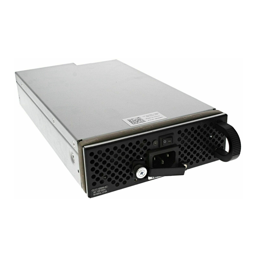
Figure 7-2. AC Power Supply Retaining Pin Threaded Hole Power LED Switch fnC0002mp AC Power Receptacle Handle Power Supply Retaining Pin Each AC power supply has one LED as described in Table 7-1. This LED does not function unless an RPM is installed. -
Page 27: Installing Power Supply Units
The chassis transmits power to connected IEEE 802.3af-compliant devices through ports that are enabled with PoE. A minimum of three power supply units (PSU) are required to enable PoE, but Dell Force10 recommends a two-plus-two redundancy configuration, so a minimum of four PSUs is recommended. -
Page 28: Removing Ac Power Supply Units
If you are not replacing the power supply, insert a panel blank. Power Cord Requirements If using a power cord other then a Dell Force10 supplied power cord, the power source end of the power cord must have an appropriately sized plug that complies with your local electrical codes. Conductor size must also conform to your local electrical codes. -
Page 29: Installing Dc Power Entry Modules
AC and DC. • If you select DC, the C150 requires at least one DC PEM for operation, but Dell Force10 recommends a one-plus-one redundancy configuration. Those DC PEMs are inserted in slots 0 and 2. -
Page 30: Installing A Dc Pem
• Rated for 60A service to allow for a fully loaded C150 system per NEC in the United States or internationally, per local safety codes. • Limit voltage drop across the cable length to 0.5V or less. Apply a coat of anti-oxidant paste to unplated metal contact surfaces before you make the cable connections. - Page 31 Step Task (continued) Slide the PEM into either power slot 0 or 2 (see (Figure 8-2). If you are installing redundant PEMS, install in both slots 0 and 2. NOTE: Fill all empty slots with blank panels (CC-C-BLNK-PWR). Figure 8-2. Insert 2 DC PEMs in Slots 0 and 2 Over-Current Switch Retaining Latch Handle...
- Page 32 Step Task (continued) Connect the -48 VDC and Return cables from each PEM to the remote power sources. Verify that the remote power source is in the OFF position. Locate the appropriate studs on the PEM front panel. • The two right-handed studs (furthest from the GND) are the return (+48V DC) connection. The cable attached to these studs is typically red.
-
Page 33: Status Led
Status LED The status LED indicates the condition of the PEM. Table 8-3. Status LED Descriptions LED Display Meaning Description No input voltage is present, or the circuit is turned off. Flashing Green Over-Current Warning The load current is above the warning level threshold. - Page 34 Installing DC Power Entry Modules...
-
Page 35: Powering Up
Powering Up Before you supply power to the chassis, Dell Force10 recommends that you re-inspect your equipment rack and chassis. Verify that: • The equipment rack is properly secured and grounded. • The chassis is bolted and secured into your equipment rack. - Page 36 Step Task In an AC power supply, the LEDs should be green. If these LEDs are not lit green: • Check that the unit is properly installed. • Verify the power source. • If the power supply cannot be verified, power off all modules and replace the unit. The fan tray LED should be green (online).
- Page 37 Figure 9-1. Boot Process Complete .*************. #### #######. ######## ####### ######### ######## ######## .#. ###### ###########. #### .##. ## ### #### ###. ### ### ### ### ### ### ## ### #### ### ######## *# -## ### ###### ### ## ######### ######## *# ### ## ## ###...
- Page 38 Powering Up...
-
Page 39: Fan Tray
The fan tray is accessible from the front of the chassis. Contact Dell Force10 Technical Support if you have questions concerning the fan tray for your system. NOTE: To ensure proper temperature and airflow control, the fan tray must always be installed and operating properly. -
Page 40: Installing The Fan Tray
Installing the Fan Tray To install the fan tray: Step Task Slide fan tray into the fan tray slot as shown in Figure 10-1. Gently push on the front of the tray until it is flush with the chassis. Use a #2 Phillips screwdriver to secure the fan tray into place by tightening the screws at the top and bottom of the fan tray. -
Page 41: Removing And Replacing Components
Removing and Replacing Components This section provides instructions for removing and replacing the following C150 components: • Removing and Replacing the Fan Tray on page 41 • Removing and Replacing Power Supply Units on page 42 • Removing and Replacing a Line Card on page 42 •... -
Page 42: Removing And Replacing Power Supply Units
Step Task Secure the fan tray into place by tightening the screws at the top and bottom of the fan tray using a #2 Phillips screwdriver. Removing and Replacing Power Supply Units WARNING: Do not remove a panel blank unless you are ready to install a power supply into that slot. After removing a power supply, immediately place a panel blank in the empty slot. -
Page 43: Removing And Replacing An Rpm
To remove and replace C150 line cards: Step Task Unplug the network interface cables connected to the line card. Extend the left and right card levers by first pressing gently down on the thumb tabs (Figure 11-1) in the ejector levers and then pulling the ejector levers simultaneously until they are in the open position, as shown in Figure 11-2. - Page 44 Step Task (continued) Extend the left and right card levers by first pressing gently down on the thumb tabs (see Figure 11-3) in the ejector levers and then pulling the ejector levers simultaneously until they are in the open position. See Figure 11-4.
-
Page 45: System Boot
System Boot When you supply power to the C150 system, the system performs a series of power-on self-tests. RPM and line card status LEDs blink during initialization. No user interaction is required as long as the boot process proceeds without interruption. Observe the process on your console monitor. When the boot process is complete, the RPM and line card status LEDs remain online (green) and the console monitor displays the command line interface (CLI) prompt, Force10>... - Page 46 Command Purpose • Enter help or? to display a list of available commands and syntax. help • Enter syntax help to display syntax information and variable descriptions. boot change {primary | If your configuration displays no pre-configured operating system boot parameters, use the boot change command to edit appropriate fields.
- Page 47 Command Purpose (continued) This command displays the current operating system boot configuration show bootvar parameters. BOOT_USER # show bootvar PRIMARY OPERATING SYSTEM BOOT PARAMETERS: ======================================== boot device : flash file name : /FTOS-CB-1.1.x.y.bin SECONDARY OPERATING SYSTEM BOOT PARAMETERS: ========================================== No Operating System boot parameters specified! This command displays information about the current boot ROM.
- Page 48 Command Purpose (continued) • Use these commands to set the speed and duplex settings for the Management interface management port interface.The default setting is full-duplex and auto-negotiation. config 100m interface management port • Use the interface management port config show command to config 10m view the Management interface’s physical settings.
-
Page 49: The Compact Flash Card
180-character local file path length, and up to a 256-character remote file path length. NOTE: Use only a Dell Force10 Compact Flash card in your C150 System. Additional cards can be purchased from Dell Force10. -
Page 50: Formatting The Compact Flash Card
To remove the flash memory card: Step Task Make sure that the In Use LED is not lit, and gently depress the flash card in the slot. The card should partially eject out of the slot. Remove the card, and place it in an antistatic bag. Formatting the Compact Flash Card New Compact Flash cards must be formatted in the C150 before use. -
Page 51: Alarms
Alarms The C150 system generates alarms for the following conditions: • fan tray status • power supply status • RPMs status • high temperature on RPMs • line cards status • high temperature on line cards A major alarm is any fault that would render the C150 system non-functional. A minor alarm is any fault that threatens the operation of the C150 system. -
Page 52: Ac Power Supplies And Alarms
Table A-1. Alarm Events and Reporting Module Alarm Event Alarm LED Reported in Status LED on event log Module Line card Hardware failure major (red) major amber Exceeds high-temperature limit major (red) major unlit Exceeds warning temperature limit minor (amber) minor green Individual interface fails... -
Page 53: B System Specifications
System Specifications This appendix contains the following major sections: • Physical Design • System Power Specifications on page 56 • Component Power Requirements on page 56 • Agency Compliance on page 56 Physical Design NOTE: See Figure B-1 Figure B-2 on page 55 for the data used for the physical dimensions. - Page 54 Figure B-1. Chassis Dimensions Length/Width 1 7 . 5 i n c h e 1 5 . 7 i n c h e fnD0012mp System Specifications...
- Page 55 Figure B-2. Chassis Dimensions Depth i n c h e 1 5 . 5 fnD0011mp System Specifications...
-
Page 56: System Power Specifications
System Power Specifications Table B-2. AC System Power Specifications Parameter Specifications Nominal Input Voltage 100 - 240 V 50/60 Hz Maximum System Power Input 4.5 KVA @ 100/120 V 4.4 KVA @ 200/240 V Maximum Power Consumption 4,420 W @ 100/120 V 4,319 W @ 200/240 V Maximum Thermal Output (856 W) at 100/120 V 2,921 BTU/hour... - Page 57 Properly shielded and grounded cables and connectors must be used in order to meet FCC emission limits. Dell Force10 is not responsible for any radio or television interference caused by using other than recommended cables and connectors or by unauthorized changes or modifications in the equipment.
-
Page 58: Safety Standards And Compliance Agency Certifications
— This is Class A product based on the standard of the Voluntary Control Council For Interference by Information Technology Equipment (VCCI). If this equipment is used in a domestic environment, radio disturbance may arise. When such trouble occurs, the user may be required to take corrective actions. -
Page 59: Electromagnetic Compatibility (Emc)
Force10 encourages owners of information technology (IT) equipment to responsibly recycle their equipment when it is no longer needed. Dell Force10 offers a variety of product return programs and services in several countries to assist equipment owners in recycling their IT products. - Page 60 EEE on the environment and human health due to the potential presence of hazardous substances in EEE. Dell Force10 products, which fall within the scope of the WEEE, are labeled with the crossed-out wheelie-bin symbol, as shown above, as required by WEEE.
-
Page 61: The Isupport Website
Contacting Technical Support The iSupport Website iSupport provides a range of documents and tools to assist you with effectively using Dell Force10 equipment and mitigating the impact of network outages. Through iSupport you can obtain technical information regarding Dell Force10 products, access to software upgrades and patches, and open and manage your Technical Assistance Center (TAC) cases. -
Page 62: Locating Serial Numbers
• Using the Create Service Request form on the iSupport page (see Contacting the Technical Assistance Center on page 61). • Contacting Dell Force10 directly by E-mail or by phone (see Contacting the Technical Assistance Center on page 61). Provide the following information when using E-mail or phone: •... - Page 63 Step Task When returning an RMA component, follow the packing and shipping directions in the Return Instructions document that accompanies the replacement component. Alternatively, contact your TAC representative for a replacement copy. Generally, you are instructed to return the RMA component in the original packaging material provided with the replacement, and to label the package with the RMA number.
- Page 64 Contacting Technical Support...
- Page 66 Printed in the U.S.A. w w w . d e l l . c o m | s u p p o r t . d e l l . c o m...
Need help?
Do you have a question about the Force10 C150 and is the answer not in the manual?
Questions and answers