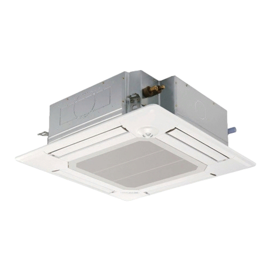
Mitsubishi Electric Mr. Slim PLA-A12BA4 Service Manual
Pla series split-type, heat pump air conditioners, ceileng cassettes, r410a
Hide thumbs
Also See for Mr. Slim PLA-A12BA4:
- Installation manual (44 pages) ,
- Installation manual (16 pages)
Table of Contents
Advertisement
SPLIT-TYPE, HEAT PUMP AIR CONDITIONERS
SPLIT-TYPE, AIR CONDITIONERS
SERVICE MANUAL
Indoor unit
[Model names]
PLA-A12BA4
PLA-A18BA4
PLA-A24BA4
PLA-A30BA4
PLA-A36BA4
PLA-A42BA4
Model name
indication
INDOOR UNIT
ON/OFF
TEMP
IR WIRELESS REMOTE
CONTROLLER
(Option)
[Service Ref.]
PLA-A12BA4
PLA-A18BA4
PLA-A24BA4
PLA-A30BA4
PLA-A36BA4
PLA-A42BA4
TEMP.
ON/OFF
WIRED REMOTE
CONTROLLER
(Option)
CONTENTS
1. REFERENCE MANUAL ........................ 2
2. SAFETY PRECAUTION ........................ 3
3. PART NAMES AND FUNCTIONS ........ 5
4. SPECIFICATIONS ................................. 8
5. NOISE CRITERION CURVES ............. 10
6. OUTLINES AND DIMENSIONS ............ 12
7. WIRING DIAGRAM ............................. 13
8. REFRIGERANT SYSTEM DIAGRAM ...... 14
9. TROUBLESHOOTING ........................ 15
10. SPECIAL FUNCTION ......................... 29
11. DISASSEMBLY PROCEDURE ........... 32
PARTS CATALOG (OCB482)
3 3 2 2 3
November 2010
No. OCH482
NOTE:
• This manual describes only
service data of the indoor units.
• RoHS compliant products have
<G> mark on the spec name
plate.
Advertisement
Table of Contents
Troubleshooting

Related Manuals for Mitsubishi Electric Mr. Slim PLA-A12BA4


Summary of Contents for Mitsubishi Electric Mr. Slim PLA-A12BA4
-
Page 1: Table Of Contents
November 2010 No. OCH482 SERVICE MANUAL Indoor unit NOTE: [Model names] [Service Ref.] • This manual describes only PLA-A12BA4 PLA-A12BA4 service data of the indoor units. • RoHS compliant products have PLA-A18BA4 <G> mark on the spec name PLA-A18BA4 plate. -
Page 2: Reference Manual
REFERENCE MANUAL OUTDOOR UNIT SERVICE MANUAL Model name Service Ref. Service Manual No. PUZ-A18/24/30/36/42NHA4 PUZ-A18/24/30/36/42NHA4 PUZ-A18/24/30/36/42NHA4-BS PUZ-A18/24/30/36/42NHA4-BS OCH481 OCB481 PUY-A12/18/24/30/36/42NHA4 PUY-A12/18/24/30/36/42NHA4 PUY-A12/18/24/30/36/42NHA4-BS PUY-A12/18/24/30/36/42NHA4-BS Remote controller (Optional parts) Radio frequency interface Wired remote controller IR wireless remote controller COOL AUTO HEAT RF thermostat TEMP. -
Page 3: Safety Precaution
SAFETY PRECAUTION 2-1. ALWAYS OBSERVE FOR SAFETY Before obtaining access to terminal, all supply circuits must be disconnected. 2-2. CAUTIONS RELATED TO NEW REFRIGERANT Cautions for units utilising refrigerant R410A Do not use refrigerant other than R410A. Use new refrigerant pipes. If other refrigerant (R22 etc.) is used, chlorine in refrige- rant can cause deterioration of refrigerant oil etc. - Page 4 [1] Cautions for service (1) Perform service after recovering the refrigerant left in the unit completely. (2) Do not release refrigerant in the air. (3) After completing service, charge the cycle with specified amount of refrigerant. (4) When performing service, install a filter drier simultaneously. Be sure to use a filter drier for new refrigerant.
-
Page 5: Part Names And Functions
PART NAMES AND FUNCTIONS Drain pipe Filter Air outlet Liquid pipe Gas pipe i-see sensor (option) Vane Air intake (Intake grille) -
Page 6: Operation Section
Wired remote controller (Option) “Sensor” indication Display Section Day-of-Week Displays when the remote controller sensor is used. Shows the current day of the week. For purposes of this explanation, all parts of the display are shown. Time/Timer Display During actual operation, only “Locked”... -
Page 7: Clock Button
IR wireless remote controller (Option) CHECK TEST RUN display Indicate that the unit is being checked or test-run. MODEL SELECT display display Blinks when model is selected. Lights up while the signal is transmitted to the indoor unit when the button is pressed. Temperature setting display Indicates the desired temperature setting which is set. -
Page 8: Specifications
SPECIFICATIONS Service Ref. PLA-A12BA4 Power supply (phase, cycle, voltage) Single phase,60Hz, 208/230V Max. Fuse Size Min. Circuit Ampacity External finish (Panel) Munsell 6.4Y 8.9/0.4 Heat exchanger Plate fin coil Fan (drive) Turbo fan (direct) Fan motor output 0.05 Fan motor F.L.A. - Page 9 Service Ref. PLA-A30BA4 Power supply (phase, cycle, voltage) Single phase,60Hz, 208/230V Max. Fuse Size Min. Circuit Ampacity External finish (Panel) Munsell 6.4Y 8.9/0.4 Heat exchanger Plate fin coil Fan (drive) Turbo fan (direct) Fan motor output 0.05 Fan motor F.L.A. 0.51 Dry: 14-16-18-21(490-570-640-740) Airflow (Low-Medium2-Medium1-High)
-
Page 10: Noise Criterion Curves
NOISE CRITERION CURVES PLA-A12BA4 PLA-A18BA4 NOTCH SPL(dB) LINE NOTCH SPL(dB) LINE High High Medium1 Medium1 Medium2 Medium2 NC-70 NC-70 NC-60 NC-60 NC-50 NC-50 NC-40 NC-40 NC-30 NC-30 APPROXIMATE APPROXIMATE THRESHOLD OF THRESHOLD OF HEARING FOR HEARING FOR NC-20 NC-20 CONTINUOUS... - Page 11 PLA-A36BA4 PLA-A42BA4 NOTCH SPL(dB) LINE NOTCH SPL(dB) LINE High High Medium1 Medium1 Medium2 Medium2 NC-70 NC-70 NC-60 NC-60 NC-50 NC-50 NC-40 NC-40 NC-30 NC-30 APPROXIMATE APPROXIMATE THRESHOLD OF THRESHOLD OF HEARING FOR HEARING FOR NC-20 NC-20 CONTINUOUS CONTINUOUS NOISE NOISE 1000 2000 4000...
-
Page 12: Outlines And Dimensions
OUTLINES AND DIMENSIONS INDOOR UNIT PLA-A12BA4 PLA-A18BA4 PLA-A24BA4 PLA-A30BA4 PLA-A36BA4 PLA-A42BA4 Unit : inch(mm) Ceiling hole 25/32 to 1-25/32(20~45) 33-27/32 to 35-13/16(860~910) 25/32 to 1-25/32(20~45) 31-7/8(810) Fresh air Detail connecting of Branch duct(Both aspects) Suspension bolt pitch 6-5/16 intake hole... -
Page 13: Wiring Diagram
WIRING DIAGRAM INDOOR UNIT PLA-A12BA4 PLA-A18BA4 PLA-A24BA4 PLA-A30BA4 PLA-A36BA4 PLA-A42BA4 [LEGEND] SYMBOL NAME SYMBOL NAME INDOOR CONTROLLER BOARD FAN MOTOR CN2L CONNECTOR (LOSSNAY) VANE MOTOR CN24 CONNECTOR <BACK-UP HEATING> TERMINAL BLOCK (INDOOR/OUTDOOR CONNECTING LINE) CN30 CONNECTOR <LLC> TB5,TB6 TERMINAL BLOCK (REMOTE CONTROLLER... -
Page 14: Refrigerant System Diagram
REFRIGERANT SYSTEM DIAGRAM PLA-A12BA4 PLA-A18BA4 PLA-A24BA4 PLA-A30BA4 PLA-A36BA4 PLA-A42BA4 Strainer (#50) Heat exchanger Refrigerant GAS pipe connection (Flare) Thermistor TH5 (Cond./ Eva. temperature) Refrigerant flow in cooling Refrigerant flow in heating Refrigerant LIQUID pipe connection (Flare) Thermistor TH2 Pipe temperature (Liquid) -
Page 15: Troubleshooting
TROUBLESHOOTING 9-1. TROUBLESHOOTING <Error code display by self-diagnosis and actions to be taken for service (summary)> Present and past error codes are logged and displayed on the wired remote controller or controller board of outdoor unit. Actions to be taken for service and the trouble reoccurrence at field are summarized in the table below. Check the contents below before investigating details. -
Page 16: Wired Remote Controller
9-2. MALFUNCTION-DIAGNOSIS METHOD BY REMOTE CONTROLLER <In case of trouble during operation> When a malfunction occurs to air conditioner, both indoor unit and outdoor unit will stop and operation lamp blinks to inform unusual stop. < Malfunction-diagnosis method at maintenance service> ■IR wireless remote controller [Procedure] 1. - Page 17 • Refer to the following tables for details on the check codes. [Output pattern A] Beeper sounds Beep Beep Beep Beep Beep Beep Beep OPERATION · · · Repeated INDICATOR lamp blink pattern Approx. 2.5 sec. 0.5 sec. 0.5 sec. 0.5 sec.
- Page 18 • On IR wireless remote controller The continuous buzzer sounds from receiving section of indoor unit. Blink of operation lamp • On wired remote controller Check code displayed in the LCD. (Refer to the previous page, check code.) • If the unit cannot be operated properly after the test run, refer to the following table to find out the cause. Symptom Cause Wired remote controller...
-
Page 19: Self-Diagnosis Action Table
Note: Refer to the manual of outdoor unit for the details of display 9-3. SELF-DIAGNOSIS ACTION TABLE such as F, U, and other E. Abnormal point and detection method Countermeasure Error Code Cause Room temperature thermistor (TH1) 1 Defective thermistor 1–3 Check resistance value of thermistor. - Page 20 Abnormal point and detection method Countermeasure Error Code Cause Freezing/overheating protection is oper- (Cooling or drying mode) (Cooling or drying mode) ating 1 Clogged filter (reduced airflow) 1 Check clogs of the filter. 1 Freezing protection (Cooling mode) 2 Short cycle of air path 2 Remove blockage.
- Page 21 Abnormal point and detection method Countermeasure Error Code Cause Pipe temperature thermistor / 1 Defective thermistor 1–3 Check resistance value of thermistor. Condenser-Evaporator (TH5) characteristics For characteristics, refer to (P1) above. 2 Check contact failure of connector (CN44) on 1 The unit is in 3-minute resume protec- 2 Contact failure of connector the indoor controller board.
- Page 22 Abnormal point and detection method Countermeasure Error Code Cause Remote controller transmission 1 Set a remote controller to main, and the other to sub. error(E3)/signal receiving error(E5) 1 2 remote controllers are set as “main.” 1 Abnormal if remote controller could not find blank of transmission path for 6 sec- (In case of 2 remote con- onds and could not transmit.
-
Page 23: Troubleshooting By Inferior Phenomena
9-4. TROUBLESHOOTING BY INFERIOR PHENOMENA Note: Refer to the manual of outdoor unit for the detail of remote controller. Phenomena Cause Countermeasure (1)Upward/downward vane 1 The vane is not downward during defrosting and heat 1 Normal operation (The vane is set to performance failure preparation and when the thermostat is OFF in HEAT horizontal regardless of remote control.) -
Page 24: Emergency Operation
9-5. EMERGENCY OPERATION 9-5-1. When IR wireless remote controller troubles or its battery is exhausted When the remote controller cannot be used When the batteries of the remote controller run out or the remote control- ler malfunctions, the emergency operation can be done using the emer- gency buttons on the grille. - Page 25 9-6. HOW TO CHECK THE PARTS PLA-A12BA4 PLA-A18BA4 PLA-A24BA4 PLA-A30BA4 PLA-A36BA4 PLA-A42BA4 Parts name Check points Room temperature Disconnect the connector then measure the resistance with a tester. thermistor (TH1) (At the ambient temperature of 10˚C[50˚F]~30˚C[86˚F]) Pipe temperature Normal Abnormal thermistor/liquid(TH2) (Refer to the Thermistor Characteristic graph.)
- Page 26 9-6-1. Thermistor <Thermistor Characteristic graph> <Thermistor for lower temperature> Room temperature thermistor(TH1) Thermistor for Pipe temperature thermistor/liquid(TH2) lower temperature Condenser/evaporator temperature thermistor(TH5) Thermistor R =15k' ± 3% Fixed number of B=3480 ± 2% t(:)Rt=15exp { 3480( 273+t T(˚F)Rt=15exp { 3480( T-32 273+ 0: (32˚F)
- Page 27 9-7. TEST POINT DIAGRAM Indoor controller board PLA-A12BA4 PLA-A18BA4 PLA-A24BA4 PLA-A30BA4 PLA-A36BA4 PLA-A42BA4 CN90 LED3 CN2L Connect to the IR wireless Transmission Connector (LOSSNAY) Vane motor output (MV) remote controller board (Indoor/outdoor) 12V pulse output (CNB) CN4Y Model selection i-see sensor...
- Page 28 1 2 3 4 5 PLA-A·BA4 settings MODELS Service MODELS Service 1 2 3 4 5 1 2 3 4 5 PLA-A12BA4 PLA-A30BA4 Capacity 1 2 3 4 5 1 2 3 4 5 settings PLA-A18BA4 PLA-A36BA4 1 2 3 4 5...
-
Page 29: Special Function
SPECIAL FUNCTION 10-1. ROTATION FUNCTION (AND BACK-UP FUNCTION, 2ND STAGE CUT-IN FUNCTION) This function is only available when using wired remote controller. 10-1-1. Operation (1) Rotation function (and Back-up function) Outline of functions · Operating the unit of main and sub alternately according to the interval setting. (Rotation function) wThe setting of main/sub unit depends on the refrigerant address. - Page 30 10-1-2. How to perform the operation of rotation function (Back-up function, 2nd stage cut-in function) Set by wired remote controller. (Maintenance monitor) NOTICE It is necessary to set the same content to both main unit and sub unit. Every time indoor controller board is replaced for servicing, it is necessary to set each function. (1) Request Code List Rotation setting Setting No.
- Page 31 (2) Setting method of each function by wired remote controller B: Refrigerant address C: Data display area D: Request code display area 1. Stop running the air-conditioner( ). 2. Press the TEST button ( ) for 3 seconds so that [Maintenance mode] appears on the screen (at After a while, [00] appears in the refrigerant address number display area.(at 3.
-
Page 32: Disassembly Procedure
DISASSEMBLY PROCEDURE PLA-A12BA4 PLA-A18BA4 PLA-A24BA4 PLA-A30BA4 PLA-A36BA4 PLA-A42BA4 Be careful when removing heavy parts. OPERATING PROCEDURE PHOTOS & ILLUSTRATIONS 1. Removing the air intake grille Figure 1 (1) Slide the knob of air intake grille toward the arrow 1 to Filter open the air intake grille. - Page 33 OPERATING PROCEDURE PHOTOS & ILLUSTRATIONS 5. Removing the fan and fan motor (MF) Coil plate Photo 3 (1) Remove the electrical box. (See Photo 2) (2) Remove the bell mouth (3 screws). (See Photo 2) (3) Remove the turbo fan nut. (4) Pull out the turbo fan.
- Page 34 OPERATING PROCEDURE PHOTOS & ILLUSTRATIONS Photo 8 9. Removing the drain pump (DP) and float switch (FS) (1) Remove the drain pan. (See Photo 6) (2) Cut the hose band and remove the hose. Float switch (3) Remove the drain pump assembly (3 screws and 2 hooks). (4) Remove the drain pump (3 screws).
- Page 36 HEAD OFFICE : TOKYO BLDG., 2-7-3, MARUNOUCHI, CHIYODA-KU, TOKYO 100-8310, JAPAN New publication, effective Nov. 2010 CCopyright 2010 MITSUBISHI ELECTRIC ENGINEERING CO., LTD. Specifications subject to change without notice. Distributed in Nov. 2010 No.OCH482 Made in Japan...
Need help?
Do you have a question about the Mr. Slim PLA-A12BA4 and is the answer not in the manual?
Questions and answers