HP Docking Station Maintenance And Service Manual
Hp docking station maintenance and service guide
Hide thumbs
Also See for Docking Station:
- Maintenance and service manual (70 pages) ,
- User manual (39 pages) ,
- Specification (1 page)
Table of Contents
Advertisement
Quick Links
Maintenance and Service
Guide
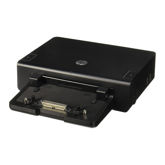
HP Docking Station
HP Advanced Docking Station
Document Part Number: 381882-002
August 2006
This guide is a troubleshooting reference used for maintaining
and servicing the HP Docking Station and the HP Advanced
Docking Station. It provides comprehensive information on
identifying docking station features, components, and spare parts;
troubleshooting problems; and performing disassembly
procedures.
Advertisement
Table of Contents
Troubleshooting

Related Manuals for HP Docking Station


Summary of Contents for HP Docking Station
-
Page 1: Maintenance And Service
Document Part Number: 381882-002 August 2006 This guide is a troubleshooting reference used for maintaining and servicing the HP Docking Station and the HP Advanced Docking Station. It provides comprehensive information on identifying docking station features, components, and spare parts;... - Page 2 © Copyright 2005, 2006 Hewlett-Packard Development Company, L.P. The information contained herein is subject to change without notice. The only warranties for HP products and services are set forth in the express warranty statements accompanying such products and services. Nothing herein should be construed as constituting an additional warranty.
-
Page 3: Table Of Contents
Contents 1 Product Description 1.1 Features ........1–3 1.2 External Components . - Page 4 5.1 Serial Number ......5–1 5.2 Preparing the Docking Station for Disassembly ..5–2 5.3 Installing the Cable Lock .
-
Page 5: Product Description
The easy docking system provides port replication and cable management in one product. The advanced docking station also provides a MultiBay II slot and an ExpressCard slot. HP Advanced Docking Station and HP Smart Adapter Maintenance and Service Guide 1–1... - Page 6 Product Description HP Docking Station and HP Smart Adapter The HP Docking Station and HP Advanced Docking Station are compatible with the following computer models: ■ HP Compaq nw9440 and nx9420 Notebook PCs ■ HP Compaq nc6230 and nc6220 Notebook PCs ■...
-
Page 7: Features
HP Smart Adapter external AC adapter (charges docked computer) ■ Lights (power, docking) ■ Integrated MultiBay II (advanced docking station only) ■ MultiBay II activity light (advanced docking station only) ■ ExpressCard slot (advanced docking station only) ■ Connectors: ❏ Monitor stand port ❏... -
Page 8: External Components
Product Description 1.2 External Components The external components on the top of the docking station are shown in the following illustration and described in Table 1-1. Top Components, Docking Station 1–4 Maintenance and Service Guide... - Page 9 Connects the computer to the docking station. Visual alignment Helps you correctly align the computer indicator when connecting it to the docking station. Computer eject button Ejects the computer from the docking and docking light station. The docking light is turned on when the computer is properly aligned.
- Page 10 Product Description The external components on the top of the advanced docking station are shown in the following illustration and described in Table 1-2. Top Components, Advanced Docking Station 1–6 Maintenance and Service Guide...
- Page 11 Connects the computer to the docking station. Visual alignment Helps you correctly align the computer indicator when connecting it to the docking station. Computer eject button Ejects the computer from the docking and docking light station. The docking light is turned on when the computer is properly aligned.
- Page 12 Product Description The external components on the left side of the docking station are shown in the following illustration and described in Table 1-3. Left-Side Components, Docking Station 1–8 Maintenance and Service Guide...
- Page 13 Product Description Table 1-3 Left-Side Components, Docking Station Item Component Description Power button and Turns on power to the computer. The light power light indicates the state of the computer, and is turned on when the computer is turned on.
- Page 14 Product Description The external components on the left side of the advanced docking station are shown in the following illustration and described in Table 1-4. Left-Side Components, Advanced Docking Station 1–10 Maintenance and Service Guide...
- Page 15 Product Description Table 1-4 Left-Side Components, Advanced Docking Station Item Component Description MultiBay II light Lights to indicate MultiBay II drive activity. MultiBay II Supports 9.5-mm MultiBay II drives such as hard drives and optical drives. USB ports (3) Allow you to connect USB devices.
- Page 16 Product Description The external components on the right side of the docking station are shown in the following illustration and described in Table 1-5. Right-Side Components, Docking Station Table 1-5 Right-Side Components, Docking Station Item Component Description Computer eject button...
- Page 17 Product Description The external components on the right side of the advanced docking station are in the following illustration below and described in Table 1-6. Right-Side Components, Advanced Docking Station Table 1-6 Right-Side Components, Advanced Docking Station Item Component Description...
- Page 18 Product Description The external components on the rear of the docking station are shown in the following illustration and described in Table 1-7. Rear Components, Docking Station Table 1-7 Rear Components, Docking Station Item Component Description Security cable slot Connects an optional security cable lock.
- Page 19 Digital video (DVI) jack Connects a DVI device such as a flat panel monitor. Power light Is turned on when the docking station is connected to AC power. RJ-11 (modem) jack Connects a telephone cable. RJ-45 (network) jack Connects a network cable.
- Page 20 Product Description The external components on the rear of the advanced docking station are shown in the following illustration and described in Table 1-8. Rear Components, Advanced Docking Station Table 1-8 Rear Components, Advanced Docking Station Item Component Description Security cable slot Connects an optional security cable lock.
- Page 21 TV. Digital video (DVI) jack Connects a DVI device such as a flat panel monitor. Power light Is turned on when the docking station is connected to AC power. RJ-11 (modem) jack Connects a telephone cable. RJ-45 (network) jack Connects a network cable.
-
Page 22: Design Overview
Product Description 1.3 Design Overview This section presents a design overview of key parts and features of the HP Docking Station and HP Advanced Docking Station. Refer to Chapter 3, “Illustrated Parts Catalog,” to identify replacement parts, and Chapter 5, “Removal and Replacement Procedures,”... -
Page 23: Troubleshooting
This chapter contains troubleshooting information for the HP Docking Station and HP Advanced Docking Station. Carefully match the symptoms of the malfunction against the problem description in the troubleshooting tables to avoid a misdiagnosis. -
Page 24: Troubleshooting Checklist
Lift the computer away from or docked in the the docking station. Then docking station. realign the computer visual alignment indicator with the indicator on the docking station, and reconnect the computer. - Page 25 Lift the computer away from light is turned on. or docked in the the docking station. Then docking station. realign the computer visual alignment indicator with the indicator on the docking station, and reconnect the computer.
- Page 26 The computer will not The connectors may Press the eject button all the disconnect from the be jammed. way in. If the computer does docking station. not disconnect, repeat this procedure to disconnect the computer. Ä Applying excessive force may damage connector pins.
- Page 27 Lift the computer away from or docked in the the docking station. Then docking station. realign the computer visual alignment indicator with the indicator on the docking station, and reconnect the computer.
- Page 28 ■ Turn on power to the There is no power to the advanced system, and then eject docking station. the disc. ■ Manually eject the disc. MultiBay II Problems and Solutions Problem Possible Cause...
-
Page 29: Illustrated Parts Catalog
3.1 Serial Number Location When ordering parts or requesting information, provide the docking station serial number and model number located on the bottom of the base plate. Serial Number Location Maintenance and Service Guide... -
Page 30: Major Components
Illustrated Parts Catalog 3.2 Major Components Major Components, HP Docking Station and HP Advanced Docking Station 3–2 Maintenance and Service Guide... - Page 31 Illustrated Parts Catalog Table 3-1 HP Docking Station/HP Advanced Docking Station Major Components Spare Part Item Description Number HP Docking Station 413627-001 (whole unit replacement) HP Advanced Docking Station 413628-001 (whole unit replacement) Power cord For use in Australia 246959-011...
-
Page 32: Miscellaneous Spares Kit
Illustrated Parts Catalog 3.3 Miscellaneous Spares Kit Miscellaneous Spares Kit 3–4 Maintenance and Service Guide... - Page 33 Illustrated Parts Catalog Table 3-2 Miscellaneous Plastics Kit Spare Part Item Description Number Miscellaneous Plastics Kit, includes: 380089-001 MultiBay II dummy card ExpressCard slot dummy card Large rubber feet, 5 each Small rubber feet, 2 each Rubber bumper (protects unit and computer when docking) Cable lock bezel blank Cable lock bezel Maintenance and Service Guide...
-
Page 34: Sequential Part Number Listing
Power cord for use in Switzerland 380089-001 Miscellaneous Plastics Kit 413627-001 HP Docking Station 413628-001 HP Advanced Docking Station 416681-001 Smart Adapter AC adapter, 120 W, PFC 416682-001 Smart Adapter AC adapter, 135 W, PFC 3–6 Maintenance and Service Guide... -
Page 35: Removal And Replacement Preliminaries
Removal and Replacement Preliminaries This chapter provides essential information for proper and safe removal and replacement service. 4.1 Tools Required You will need the following tools to complete the removal and replacement procedures: ■ Magnetic screwdriver ■ Phillips P0 screwdriver ■... -
Page 36: Plastic Parts
Removal and Replacement Preliminaries Plastic Parts Using excessive force during disassembly and reassembly can damage plastic parts. Use care when handling the plastic parts. Apply pressure only at the points designated in the maintenance instructions. Cables and Connectors Ä CAUTION: When servicing the expansion base, ensure that cables are placed in their proper locations during the reassembly process. -
Page 37: Packaging And Transporting Precautions
Removal and Replacement Preliminaries 4.4 Packaging and Transporting Precautions Use the following grounding precautions when packaging and transporting equipment: ■ To avoid hand contact, transport products in static-safe containers, such as tubes, bags, or boxes. ■ Protect all electrostatic-sensitive parts and assemblies with conductive or approved containers or packaging. -
Page 38: Workstation Precautions
Removal and Replacement Preliminaries 4.5 Workstation Precautions Use the following grounding precautions at workstations: ■ Cover the workstation with approved static-shielding material (refer to Table 4-2, "Static-Shielding Materials"). ■ Use a wrist strap connected to a properly grounded work surface and use properly grounded tools and equipment. ■... - Page 39 Removal and Replacement Preliminaries ■ When standing, use foot straps and a grounded floor mat. Foot straps (heel, toe, or boot straps) can be used at standing workstations and are compatible with most types of shoes or boots. On conductive floors or dissipative floor mats, use foot straps on both feet with a minimum of one megohm resistance between the operator and ground.
- Page 40 Removal and Replacement Preliminaries Table 4-1 shows how humidity affects the electrostatic voltage levels generated by different activities. Table 4-1 Typical Electrostatic Voltage Levels Relative Humidity Event Walking across carpet 35,000 V 15,000 V 7,500 V Walking across vinyl floor 12,000 V 5,000 V 3,000 V...
-
Page 41: Removal And Replacement Procedures
Procedures This chapter provides removal and replacement procedures. You must remove up to three screws (for the cable lock) when servicing the docking station. Make note of each screw location during removal and replacement. Refer to Appendix A, “Screw Listing,”... -
Page 42: Preparing The Docking Station For Disassembly
Perform the following steps before disassembling the docking station: 1. If a computer is connected to the docking station, close the computer. If you close the computer with the power turned on, the computer may enter Standby mode. To resume operation after undocking, open the computer, and then press the power button. - Page 43 3. Lift up the computer 2 and set it aside. Undocking the Computer 4. Disconnect all external devices connected to the docking station. 5. Disconnect the power cord from the docking station. Maintenance and Service Guide 5–3...
-
Page 44: Installing The Cable Lock
Security solutions are designed to act as deterrents. These deterrents may not prevent a product from being mishandled or stolen. The cable lock allows you to secure the docking station and a docked computer, or the advanced docking station with a docked computer and MultiBay II drive installed. - Page 45 To install the cable lock: 1. Loop the cable around a stationary object. 2. Turn the docking station upside down, and then remove the three PM2.5x5 screws from the cable lock bezel 1. 3. Remove the bezel from the docking station 2, and then remove the bezel blank from the cable lock bezel 3.
- Page 46 1. 5. Insert the cable into the recessed cable channel in the base of the docking station 2. Inserting the Cable Lock 5–6 Maintenance and Service Guide...
- Page 47 6. Turn the key counterclockwise to lock 1. 7. Remove the key from the lock 2. 8. Reinsert the cable lock bezel onto the docking station 3. 9. Replace the screws to secure the bezel 4. Securing the Cable Lock Maintenance and Service Guide 5–7...
- Page 48 Removal and Replacement Procedures The following illustration shows a docking station with the cable lock installed. Docking Station with Cable Lock Inserted 5–8 Maintenance and Service Guide...
-
Page 49: Specifications
Specifications This chapter provides physical and performance specifications. Table 6-1 HP Docking Station Specifications Dimensions Height 28.0 cm 11.02 in Width 6.1 cm 2.40 in Length 15.3 cm 6.02 in Weight 1.02 kg 2.24 lb Temperature Operating 10°C to 35°C 50°F to 95°F... - Page 50 Specifications Table 6-1 HP Docking Station Specifications (Continued) Altitude Operating 0 m to 3,048 m 0 ft to 10,000 ft Non-operating 0 m to 9,144 m 0 ft to 30,000 ft Shock Operating 10 G, 11 ms, half-sine Non-operating 60 G, 11 ms, half-sine...
- Page 51 Specifications Table 6-2 HP Advanced Docking Station Specifications Dimensions Height 28.0 cm 11.02 in Width 6.1 cm 2.40 in Length 24.3 cm 9.56 in Weight 1.78 kg 3.93 lb Temperature Operating 10°C to 35°C 50°F to 95°F Nonoperating -10°C to 60°C 14°F to 140°F...
- Page 52 Specifications Table 6-2 HP Advanced Docking Station Specifications (Continued) Altitude Operating 0 m to 3,048 m 0 ft to 10,000 ft Non-operating 0 m to 9,144 m 0 ft to 30,000 ft Shock Operating 10 G, 11 ms, half-sine Non-operating...
- Page 53 Screw Listing This appendix provides specification and reference information for the screws used in the HP Docking Station and the HP Advanced Docking Station. Table A-1 Phillips M2.5×5.0 Screw Head Color Qty. Length Thread Width Black 5.0 mm 2.5 mm 4.0 mm...
- Page 54 Connector Pin Assignments Table B-1 Audio-In (Microphone) Jack Signal Signal Audio signal in Ground Audio signal in CPQ Manual Title B–1...
- Page 55 Connector Pin Assignments Table B-2 Audio-Out (Headphone) Jack Signal Signal Audio out, left channel Ground Audio out, right channel B–2 CPQ Manual Title...
- Page 56 Connector Pin Assignments Table B-3 External Monitor Port Signal Signal Red analog +5 VDC Green analog Ground Blue analog Monitor detect Not connected DDC 2B data Ground Horizontal sync Ground analog Vertical sync Ground analog DDC 2B clock Ground analog CPQ Manual Title B–3...
- Page 57 Connector Pin Assignments Table B-4 Keyboard/Mouse Connector Signal Signal Keyboard/mouse DATA +5 VDC Keyboard/mouse DATA Keyboard/mouse CLK Ground Keyboard/mouse CLK B–4 CPQ Manual Title...
-
Page 58: Parallel Port
Connector Pin Assignments Table B-5 Parallel Port Signal Signal Strobe Auto linefeed Data bit 0 Error Data bit 1 Initialize printer Data bit 2 Select in Data bit 3 Ground Data bit 4 Ground Data bit 5 Ground Data bit 6 Ground Data bit 7 Ground... - Page 59 Connector Pin Assignments Table B-6 RJ-11 (Modem) Jack Signal Signal Unused Unused Unused Ring Unused Table B-7 RJ-45 (Network) Jack Signal Signal Transmit + Unused Transmit – Receive – Receive + Unused Unused Unused B–6 CPQ Manual Title...
- Page 60 Connector Pin Assignments Table B-8 Serial Port Signal Signal Carrier detect Data set ready Receive data Ready to send Transmit data Clear to send Data terminal ready Ring indicator Ground CPQ Manual Title B–7...
- Page 61 Connector Pin Assignments Table B-9 S-Video-Out Jack Signal Signal TV-Ground TV-CD TV-CVBS TV-Ground TV-Ground TV-YD TV-Ground Table B-10 Universal Serial Bus Port Signal Signal +5 VDC Data + Data – Ground B–8 CPQ Manual Title...
- Page 62 Power Cord Set Requirements 3-Conductor Power Cord Set The wide range input feature of the docking station permits it to operate from any line voltage from 100 to 120 or 220 to 240 volts AC. The power cord set included with the docking station meets the requirements for use in the country where the equipment is purchased.
- Page 63 ■ The appliance coupler must meet the mechanical configuration of an EN 60 320/IEC 320 Standard Sheet C13 connector for mating with the appliance inlet on the back of the docking station. C–2 CPQ Manual Title...
- Page 64 Power Cord Set Requirements Country-Specific Requirements 3-Conductor Power Cord Set Requirements Country/Region Accredited Agency Applicable Note Number Australia EANSW Austria Belgium CEBC Canada Denmark DEMKO Finland FIMKO France Germany Italy Japan METI ✎ NOTES: 1. The flexible cord must be <HAR> Type HO5VV-F, 3-conductor, 1.0 mm² conductor size.
- Page 65 Power Cord Set Requirements 3-Conductor Power Cord Set Requirements (Continued) Country/Region Accredited Agency Applicable Note Number Korea The Netherlands KEMA Norway NEMKO People’s Republic of China Sweden SEMKO Switzerland Taiwan BSMI United Kingdom United States ✎ NOTES: 1. The flexible cord must be <HAR> Type HO5VV-F, 3-conductor, 1.0 mm² conductor size.
- Page 66 1–17 advanced docking station computer eject button 1–5 spare part number 3–3 3–6 1–7 1–12 1–13 specifications 6–3 computer eject mechanisms See also docking station 1–5 1–7 audio-in jack connection troubleshooting location 1–15 1–17 2–2 2–3 pin assignments B–1 connector pin assignments audio-out jack audio-in jack B–1...
- Page 67 1–7 docking light 1–5 1–7 1–12 docking posts 1–5 1–7 illustrated parts catalog 3–1 docking problems 2–2 2–3 docking station keyboard connector 1–17 spare part number 3–3 3–6 location 1–15 specifications 6–1 pin assignments B–4 See also advanced docking station left-side components 1–8...
- Page 68 1–17 set requirements C–2 pin assignments B–7 spare part number 3–3 3–6 service considerations 4–1 power light 1–5 1–7 1–9 spare part number 1–11 1–15 1–17 advanced docking station 3–3 3–6 docking station 3–3 3–6 Maintenance and Service Guide Index–3...
- Page 69 Index Miscellaneous Plastics Kit 3–4 power cord 3–3 specifications advanced docking station 6–3 docking station 6–1 static-shielding materials 4–6 S-Video-out jack location 1–15 1–17 pin assignments B–8 tools required 4–1 top components 1–4 1–6 transporting precautions 4–3 troubleshooting checklist 2–1 undocking problems 2–4...
Need help?
Do you have a question about the Docking Station and is the answer not in the manual?
Questions and answers