Table of Contents
Advertisement
Quick Links
Advertisement
Table of Contents
Troubleshooting

Related Manuals for HP t820


Summary of Contents for HP t820
- Page 1 Maintenance & Service Guide HP t820 Flexible Thin Client...
- Page 2 © Copyright 2013 Hewlett-Packard Development Company, L.P. The information contained herein is subject to change without notice. Microsoft and Windows are U.S. registered trademarks of the Microsoft group of companies. The only warranties for HP products and services are set forth in the express warranty statements accompanying such products and services.
-
Page 3: About This Book
About This Book WARNING! Text set off in this manner indicates that failure to follow directions could result in bodily harm or loss of life. CAUTION: Text set off in this manner indicates that failure to follow directions could result in damage to equipment or loss of information. - Page 4 About This Book...
-
Page 5: Table Of Contents
Table of contents 1 Product features ....................... 1 Standard configuration features ....................1 Front panel components ......................2 Rear panel components ......................3 Serial number location ......................4 2 Illustrated parts catalog ....................5 Computer major components ..................... 5 Drives ............................. 6 Misc boards .......................... - Page 6 Lithium coin cell battery .................... 16 4 Removal and replacement procedures ................17 Preparation for disassembly ....................17 Access panel ......................... 18 Front bezel ..........................19 Front bezel security ........................ 20 Memory ..........................22 SODIMMs ......................22 DDR3-SDRAM SODIMMs ..................22 Populating SODIMM sockets ..................
- Page 7 Computer Setup—Advanced ..................66 Recovering the Configuration Settings ..................67 Changing BIOS Settings from the REPSETUP utility ..............68 Appendix C Diagnostics and Troubleshooting ..............71 LEDs ............................. 71 Wake-on LAN ........................72 Power-On Sequence ....................... 72 Resetting the Administrator and power-on passwords ..............73 Power-On Diagnostic Tests ......................
- Page 8 Index ..........................94 viii...
-
Page 9: Product Features
Product features Standard configuration features Standard configuration features... -
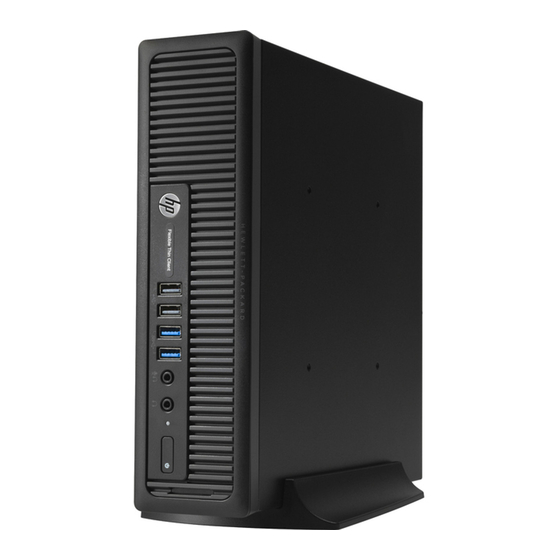
Page 10: Front Panel Components
Front panel components USB 2.0 Ports (black) Headphone Connector USB 3.0 Ports (blue) Hard Drive Activity Light Microphone/Headphone Connector Dual-State Power Button NOTE: When a device is plugged into the Microphone/Headphone Connector, a dialog box appears asking if you want to use the connector for a microphone Line-In device or a headphone. You can reconfigure the connector at any time by double-clicking the Audio Manager icon in the Windows ®... -
Page 11: Rear Panel Components
Rear panel components Line-Out Connector for powered audio devices Power Cord Connector (green) USB 2.0 Ports (black) Line-In Audio Connector (blue) USB 3.0 Ports (blue) RJ-45 Network Connector Dual-Mode DisplayPort Monitor Connectors PS/2 Mouse Connector (green) PS/2 Keyboard Connector (purple) Fiber NIC (optional) VGA Monitor Connector NOTE:... -
Page 12: Serial Number Location
Serial number location Each computer has a unique serial number and a product ID number that are located on the exterior of the computer. Keep these numbers available for use when contacting customer service for assistance. Chapter 1 Product features... -
Page 13: Illustrated Parts Catalog
Illustrated parts catalog Computer major components Item Description Spare part number Access panel 732763-001 Front bezel 732764-001 Stand 612496-001 System board (includes replacement thermal material) For use in models with WES7 737729-001 AC adapter 180W, standard 613766-001 135W, standard 648964-001 Memory modules (PC3-12800) 8-GB 689374-001... -
Page 14: Drives
Item Description Spare part number 4-GB 689373-001 2-GB 689372-001 Processors (include replacement thermal material) Intel Pentium G3220 (3.0-GHz, 3-MB L3 cache, 54W) 742564-001 Intel Core i5 4570s (2.9-GHz, 6-MB L3 cache, 65W) 732505-001 Drives Description Spare part number mSATA drive 32-GB 719566-001 16-GB... -
Page 15: Misc Parts
Misc parts Item Description Spare part number Heat sink for use with the processor (includes replacement thermal material) 587456-001 Heat sink for use with the discrete graphics card (includes replacement thermal 689369-001 material; not illustrated) Power switch assembly 732767-001 Speaker 689384-001 Fan, rear 691352-001... -
Page 16: Sequential Part Number Listing
Sequential part number listing Spare part Description number 587456-001 Heat sink for use with the processor (includes thermal material) 612496-001 Stand 613766-001 180-W power adapter, standard 638814-001 SATA data cable, 25.2-inch 638816-001 Hood sensor 648964-001 AC adapter, 135W, standard 674315-001 Mouse, PS2, optical 674316-001 Mouse, USB, optical... - Page 17 Spare part Description number 737729-001 System board for use in models with WES7 (includes replacement thermal material) 742564-001 Intel Pentium G3220 processor (3.0-GHz, 3-MB L3 cache, 54W) Sequential part number listing...
-
Page 18: Routine Care And Disassembly Preparation
Routine care and disassembly preparation This chapter provides general service information for the computer. Adherence to the procedures and precautions described in this chapter is essential for proper service. CAUTION: When the computer is plugged into an AC power source, voltage is always applied to the system board. -
Page 19: Generating Static
Generating static The following table shows that: Different activities generate different amounts of static electricity. ● Static electricity increases as humidity decreases. ● Relative Humidity Event Walking across carpet 7,500 V 15,000 V 35,000 V Walking across vinyl floor 3,000 V 5,000 V 12,000 V Motions of bench worker... -
Page 20: Personal Grounding Methods And Equipment
Personal grounding methods and equipment Use the following equipment to prevent static electricity damage to equipment: Wrist straps are flexible straps with a maximum of one-megohm ± 10% resistance in the ground ● cords. To provide proper ground, a strap must be worn snug against bare skin. The ground cord must be connected and fit snugly into the banana plug connector on the grounding mat or workstation. -
Page 21: Operating Guidelines
Conductive foam ● Conductive tabletop workstations with ground cord of one-megohm +/- 10% resistance ● Static-dissipative table or floor mats with hard tie to ground ● Field service kits ● Static awareness labels ● Wrist straps and footwear straps providing one-megohm +/- 10% resistance ●... -
Page 22: Routine Care
Never cover the ventilation slots on the monitor with any type of material. ● Install or enable power management functions of the operating system or other software, including ● sleep states. Routine care General cleaning safety precautions Never use solvents or flammable solutions to clean the computer. Never immerse any parts in water or cleaning solutions;... -
Page 23: Cleaning The Monitor
CAUTION: Use safety glasses equipped with side shields before attempting to clean debris from under the keys. Visible debris underneath or between the keys may be removed by vacuuming or shaking. ● Canned, pressurized air may be used to clean debris from under the keys. Caution should be used ●... -
Page 24: Screws
Diagnostics software ● Tamper-resistant T-15 wrench ● Screws The screws used in the computer are not interchangeable. They may have standard or metric threads and may be of different lengths. If an incorrect screw is used during the reassembly process, it can damage the unit. -
Page 25: Removal And Replacement Procedures
Removal and replacement procedures Adherence to the procedures and precautions described in this chapter is essential for proper service. After completing all necessary removal and replacement procedures, run the Diagnostics utility to verify that all components operate properly. NOTE: Not all features listed in this guide are available on all computers. Preparation for disassembly Routine care and disassembly preparation on page 10 for initial safety procedures. -
Page 26: Access Panel
Access panel Description Spare part number Access panel 732763-001 To access internal components, you must remove the access panel: Prepare the computer for disassembly (Preparation for disassembly on page 17). Loosen the thumbscrew on the rear of the computer (1), slide the access panel toward the rear of the computer, then lift it off (2). -
Page 27: Front Bezel
Front bezel Description Spare part number Front bezel 732764-001 Prepare the computer for disassembly (Preparation for disassembly on page 17). Remove the access panel (Access panel on page 18). Lift up the three tabs on the side of the bezel (1), then rotate the bezel off the chassis (2). To install the front bezel, reverse the removal procedure. -
Page 28: Front Bezel Security
Front bezel security The front bezel can be locked in place by installing a security screw provided by HP. To install the security screw: Prepare the computer for disassembly (Preparation for disassembly on page 17). Remove the access panel (Access panel on page 18). - Page 29 Install the security screw through the middle front bezel release tab and into the chassis to secure the front bezel in place. Front bezel security...
-
Page 30: Memory
Memory Description Spare part number 8-GB, PC3-12800, SODIMM 689374-001 4-GB, PC3-12800, SODIMM 689373-001 2-GB, PC3-12800, SODIMM 689372-001 The computer comes with double data rate 3 synchronous dynamic random access memory (DDR3- SDRAM) small outline dual inline memory modules (SODIMMs). SODIMMs The memory sockets on the system board can be populated with up to two industry-standard SODIMMs. -
Page 31: Populating Sodimm Sockets
Populating SODIMM sockets There are two SODIMM sockets on the system board, with one socket per channel. The sockets are labeled DIMM1 and DIMM3. The DIMM1 socket operates in memory channel B. The DIMM3 socket operates in memory channel A. Item Description System Board Label... -
Page 32: Installing Sodimms
Installing SODIMMs CAUTION: You must disconnect the power cord and wait approximately 30 seconds for the power to drain before adding or removing memory modules. Regardless of the power-on state, voltage is always supplied to the memory modules as long as the computer is plugged into an active AC outlet. Adding or removing memory modules while voltage is present may cause irreparable damage to the memory modules or system board. -
Page 33: Front Fan
Front fan Description Spare part number Front fan 732765-001 The front fan sits against the front on the left side of the chassis. Prepare the computer for disassembly (Preparation for disassembly on page 17). Remove the access panel (Access panel on page 18). -
Page 34: Speaker
Speaker Description Spare part number Speaker 689384-001 The speaker is secured to the front of the chassis between the fan and the I/O ports. Remove the screws from the outside and then remove the speaker from the inside. Prepare the computer for disassembly (Preparation for disassembly on page 17). -
Page 35: Heat Sink
Heat sink Description Spare part number Heat sink 587456-001 The heat sink is secured by four Torx screws. It does not have an attached fan. Prepare the computer for disassembly (Preparation for disassembly on page 17). Remove the access panel (Access panel on page 18). - Page 36 If using a new heat sink, go to step 3. If reusing the existing heat sink, clean bottom of the heat sink and apply the thermal material provided in the spares kit to the top of the processor. Position the heat sink atop the processor. If using a new heat sink, remove the protective covering from the bottom of the heat sink and place it in position atop the processor.
-
Page 37: Processor
Processor Description Spare part number Intel Pentium G3220 (3.0-GHz, 3-MB L3 cache, 54W) 742564-001 Intel Core i5 4570s (2.9-GHz, 6-MB L3 cache, 65W) 732505-001 Prepare the computer for disassembly (Preparation for disassembly on page 17). Remove the access panel (Access panel on page 18). -
Page 38: Smart Cover Lock (Solenoid Lock)
Smart Cover Lock (solenoid lock) Description Spare part number Solenoid lock 732772-001 NOTE: The Smart Cover Lock is an optional feature included on some models only. The Smart Cover Lock is a software-controllable cover lock, controlled by the setup password. This lock prevents unauthorized access to the internal components. - Page 39 From the outside, rear side of the chassis, remove the silver security screw that secures the lock to the chassis. From the inside of the chassis, lift the lock up to gain access to the system board connector. Smart Cover Lock (solenoid lock)
- Page 40 Disconnect the cable from the system board connector labeled HLOCK. To install the Smart Cover Lock, reverse the removal procedure. Refer to the following image for the location of the slots on the back of the chassis in which to install the lock.
- Page 41 Smart Cover Lock (solenoid lock)
-
Page 42: Drive Cage (Fiber Nic Assembly Holder)
Drive cage (fiber NIC assembly holder) Description Spare part number Drive cage 732761-001 The drive cage sits behind the USB ports on the front of the chassis. On this thin client, the drive cage does not support drives. The only component the drive cage houses is the fiber NIC assembly. -
Page 43: Msata Drive
mSATA drive Description Spare part number 32-GB mSATA drive 719566-001 16-GB mSATA drive 719565-001 The mSATA drive is installed onto the system board underneath the hard drive cage. Remove the mSATA drive: Prepare the computer for disassembly (Preparation for disassembly on page 17). -
Page 44: Hood Sensor
Hood sensor Description Spare part number Hood sensor 638816-001 Prepare the computer for disassembly (Preparation for disassembly on page 17). Remove the access panel (Access panel on page 18). Remove the drive cage (Drive cage (fiber NIC assembly holder) on page 34). -
Page 45: Installing The Fiber Nic Assembly
Installing the fiber NIC assembly Description Spare part number Fiber NIC assembly 729624-001 Prepare the computer for disassembly (Preparation for disassembly on page 17). Remove the access panel (Access panel on page 18). Remove the drive cage (Drive cage (fiber NIC assembly holder) on page 34). - Page 46 Insert the smaller fiber card into the PCI slot in the system board (1), and rotate the board downward. Insert the two Torx screws that secure the card onto the system board (1), and the insert the FFC cable into the connector on the card. Install the hard drive carrier assembly into the hard drive cage.
- Page 47 Route the cable through the front of the hard drive carrier cage, and then insert the cable into the connector on the larger fiber card.. Install the clips in the two locations as shown in the following image, and then route the cables through the clips.
- Page 48 Disconnect the cable ends from the connector. On the outside, rear of the computer, install the connector by inserting the connector through the slot on the computer, and then inserting the two Torx screws to secure the connector. From the inside, rear of the computer, plug the cables into the connector. Plug the white cable into the port labeled ‘R’...
-
Page 49: Wlan Module
WLAN module Description Spare part number HP WLAN 802.11 a/b/g/n 2x2 PCIe NIC 695915-001 Prepare the computer for disassembly (Preparation for disassembly on page 17). Remove the access panel (Access panel on page 18). Remove the drive cage (Drive cage (fiber NIC assembly holder) on page 34). -
Page 50: Graphics Board
Graphics board Description Spare part number AMD Radeon HD 7650A 2GB MXM Graphics 708866-001 CAUTION: Be very careful when removing or replacing the system board to prevent damaging it. Prepare the computer for disassembly (Preparation for disassembly on page 17). Remove the access panel (Access panel on page 18). -
Page 51: Power Switch
Power switch Description Spare part number Power switch 732767-001 Prepare the computer for disassembly (Preparation for disassembly on page 17). Remove the access panel (Access panel on page 18). Remove the front bezel (Front bezel on page 19). Remove the drive cage (Drive cage (fiber NIC assembly holder) on page 34). -
Page 52: System Board
System board Description Spare part number System board for use in models with WES7 737729-001 Front I/O panel 732762-001 CAUTION: Be very careful when removing or replacing the system board to prevent damaging it. When replacing the system board, make sure to remove the following components (as applicable) from the old system board and install them on the new system board: Memory modules (Memory on page... - Page 53 Remove the front I/O panel: Remove the Torx T15 screw from the right side of the panel that secures it to the front of the chassis. Press the tab on right side of the panel (1), and then swing the right side of the cage away from the chassis to remove it (2).
- Page 54 Remove the three remaining Torx T15 screws that secure the system board to the chassis. Slide system board toward the front of the unit until the rear connectors are clear of their slots in the chassis (1). Lift the rear of the system board until it clears the chassis, and then remove the system board from the chassis (2).
-
Page 55: Rear Fan
Rear fan Description Spare part number Rear fan 691352-001 The rear fan is secured to the rear right corner of the chassis. You must remove the system board before you can remove the rear fan. Prepare the computer for disassembly (Preparation for disassembly on page 17). - Page 56 From the inside of the chassis, slide the fan out from underneath the chassis lip, and then remove the fan. To install the rear fan, reverse the removal procedure. Chapter 4 Removal and replacement procedures...
-
Page 57: Antennas
Antennas Two antennas are secured to chassis – one on the front, one on the back. You must remove all other components to remove the antennas. Prepare the computer for disassembly (Preparation for disassembly on page 17). Remove the access panel (Access panel on page 18). - Page 58 Pull the antenna out of the clips on the front of the chassis (2), and then pull the antenna out of the hole it routes through (3). To remove the rear antenna, from the inside of the front of the chassis, remove the antenna from the plastic clips attached to the side of the chassis.
- Page 59 From the outside of the rear of the chassis, remove the two Torx T8 screws that secure the antenna to the chassis. Pull the antenna through the hole it routes through. To install the rear fan, reverse the removal procedure. Antennas...
-
Page 60: Changing From Desktop To Tower Configuration
Changing from desktop to tower configuration The computer can be used in a tower orientation with the tower stand included with the computer. Remove/disengage any security devices that prohibit opening the computer. Remove all removable media, such as compact discs or USB flash drives, from the computer. Turn off the computer properly through the operating system, then turn off any external devices. -
Page 61: Port Cover
Port cover An optional rear port cover is available for the computer. To install the port cover: Thread the cables through the bottom hole on the port cover (1) and connect the cables to the rear ports on the computer. Insert the hooks on the port cover into the slots on the rear of the chassis, then slide the cover to the right to secure it in place (2). -
Page 62: Power Supply, External
Power supply, external The chassis uses an external power supply. WARNING! To reduce potential safety issues, only the power supply provided with the computer, a replacement power supply provided by HP, or a power supply purchased as an accessory from HP should be used with the computer. -
Page 63: Appendix A Battery Replacement
Battery replacement The battery that comes with the computer provides power to the real-time clock. When replacing the battery, use a battery equivalent to the battery originally installed in the computer. The computer comes with a 3-volt lithium coin cell battery. WARNING! The computer contains an internal lithium manganese dioxide battery. - Page 64 Locate the battery and battery holder on the system board. NOTE: On some computer models, it may be necessary to remove an internal component to gain access to the battery. Depending on the type of battery holder on the system board, complete the following instructions to replace the battery.
- Page 65 Insert the new battery and position the clip back into place. NOTE: After the battery has been replaced, use the following steps to complete this procedure. Replace the access panel. Plug in the computer and turn on power to the computer. Reset the date and time, your passwords, and any special system setups using Computer Setup.
-
Page 66: Appendix B Computer Setup (F10) Utility, Bios Settings
Computer Setup (F10) Utility, BIOS Settings Computer Setup (F10) Utilities Use Computer Setup (F10) Utility to do the following: Change factory default settings. ● Set the system date and time. ● Set, view, change, or verify the system configuration, including settings for processor, graphics, ●... -
Page 67: Using Computer Setup (F10) Utilities
Using Computer Setup (F10) Utilities Computer Setup can be accessed only by turning the computer on or restarting the system. To access the Computer Setup Utilities menu, complete the following steps: Turn on or restart the computer. Press either while the “Press the ESC key for Startup Menu” message is displayed at the bottom of the screen. -
Page 68: Computer Setup-File
Computer Setup—File NOTE: Support for specific Computer Setup options may vary depending on the hardware configuration. Table B-2 Computer Setup—File Option Description System Information Lists: Product name ● SKU number (some models) ● Processor type/speed/stepping ● Cache size (L1/L2) ● Installed memory size/speed, number of channels (single or dual) (if applicable) ●... -
Page 69: Computer Setup-Storage
Computer Setup—Storage NOTE: Support for specific Computer Setup options may vary depending on the hardware configuration. Table B-3 Computer Setup—Storage Option Description Device Lists all installed BIOS-controlled storage devices. When a device is selected, detailed information Configuration and options are displayed. The following options may be presented: Hard Disk: Size, model, firmware version, serial number, connector color. -
Page 70: Computer Setup-Security
Computer Setup—Security NOTE: Support for specific Computer Setup options may vary depending on the hardware configuration. Table B-4 Computer Setup—Security Option Description Setup Password Allows you to set and enable a setup (administrator) password. NOTE: If the setup password is set, it is required to change Computer Setup options, flash the ROM, and make changes to certain plug and play settings under Windows. - Page 71 Table B-4 Computer Setup—Security (continued) USB3 Port 1 ◦ USB3 Port 2 ◦ Accessory USB Ports ● USB Port 1 ◦ Slot Security Allows you to disable any PCI Express slot. Default is enabled. Network Boot Enables/disables the computer’s ability to boot from an operating system installed on a network server.
- Page 72 Table B-4 Computer Setup—Security (continued) System Security Data Execution Prevention (enable/disable) - Helps prevent operating system security breaches. (some models: these Default is enabled. options are hardware SVM CPU Virtualization (enable/disable). Controls the virtualization features of the processor. dependent) Changing this setting requires turning the computer off and then back on. Default is disabled. Embedded Security Device Support (some models) (enable/disable) - Permits activation and deactivation of the Embedded Security Device.
-
Page 73: Computer Setup-Power
Computer Setup—Power NOTE: Support for specific Computer Setup options may vary depending on the hardware configuration. Table B-5 Computer Setup—Power Option Description OS Power Idle Power Savings—Extended/Auto/Normal. Allows certain operating systems to decrease ● Management the processors power consumption when the processor is idle. Default is extended. Runtime Power Management—... -
Page 74: Computer Setup-Advanced
Computer Setup—Advanced NOTE: Support for specific Computer Setup options may vary depending on the hardware configuration. Table B-6 Computer Setup—Advanced (for advanced users) Option Heading Power-On Options Allows you to set: POST mode (QuickBoot, Clear Memory, FullBoot, or FullBoot Every x Days). ●... -
Page 75: Recovering The Configuration Settings
Table B-6 Computer Setup—Advanced (for advanced users) (continued) Bus Options On some models, allows you to enable or disable: PCI SERR# Generation. Default is enabled. ● PCI VGA Palette Snooping, which sets the VGA palette snooping bit in PCI configuration ●... -
Page 76: Changing Bios Settings From The Repsetup Utility
Changing BIOS Settings from the REPSETUP utility Some BIOS settings may be changed locally within the operating system without having to go through the F10 utility . This table identifies the items that can be controlled with this method. BIOS Setting Default Value Other Values Setup Language... - Page 77 Network Service Boot Disable Enable Enter Ownership Tag Enter UUID Data Execution Prevention Disable Enable SVM CPU Virtualization Disable Enable Activate Embedded Security Disable Enable On Next Boot Embedded Security F1 to Boot Allow user to reject, No Prompts Activation Policy OS management of Disable Enable...
- Page 78 PCI VGA Palette Snooping Disable Enable Printer Mode EPP+ECP Bi-Directional, Output-Only Num Lock State at Power- Integrated Video Auto Disable, Force UMA Size 512M 32M, 64M, 256M, 512M, 1G Internal Speaker Enable Disable NIC Option ROM Disable Download Default Setup Leave Defaults As Is (No Save Current Settings as Default, Restore Factory Settings as Default Update)
-
Page 79: Appendix C Diagnostics And Troubleshooting
Diagnostics and Troubleshooting LEDs Table C-1 Power and IDE Flash Activity LEDs Status Power LED Off When the unit is plugged into the wall socket and the Power LED is off, the unit is powered off. However, the network can trigger a Wake On LAN event in order to perform management functions. -
Page 80: Wake-On Lan
Wake-on LAN Wake-on LAN (WOL) allows a computer to be turned on or resumed from sleep or hibernation state by a network message. You can enable or disable WOL in Computer Setup using the S5 Maximum Power Savings setting. To enable or disable WOL: Turn on or restart the computer. -
Page 81: Resetting The Administrator And Power-On Passwords
Resetting the Administrator and power-on passwords You can reset the Administrator and power-on passwords as follows: Turn off the computer and disconnect the power cord from the power outlet. Remove the side access panel and the metal side cover. Remove the password jumper from the system board header labeled PSWD. Replace the metal side cover and the side access panel. -
Page 82: Interpreting Post Diagnostic Front Panel Leds And Audible Codes
Interpreting POST Diagnostic Front Panel LEDs and Audible Codes This section covers the front panel LED codes as well as the audible codes that may occur before or during POST that do not necessarily have an error code or text message associated with them. WARNING! When the computer is plugged into an AC power source, voltage is always applied to the system board. - Page 83 Table C-3 Diagnostic Front Panel LEDs and Audible Codes (continued) Activity Beeps Possible Cause Recommended Action Red Power LED flashes four Power failure (power Check if a device is causing the problem by times, once every second, supply is overloaded). removing ALL attached devices.
- Page 84 Table C-3 Diagnostic Front Panel LEDs and Audible Codes (continued) Activity Beeps Possible Cause Recommended Action Red Power LED flashes eight Invalid ROM based on Reflash the system ROM with the latest BIOS times, once every second, bad checksum. image using the BIOS Recovery procedure. followed by a two second Replace the system board.
-
Page 85: Post Numeric Codes And Text Messages
POST Numeric Codes and Text Messages This section covers those POST errors that have numeric codes associated with them. The section also includes some text messages that may be encountered during POST. NOTE: The computer will beep once after a POST text message is displayed on the screen. Table C-4 Numeric Codes and Text Messages Control panel message... - Page 86 Table C-4 Numeric Codes and Text Messages (continued) Control panel message Description Recommended action 301-Keyboard Error Keyboard failure. Reconnect keyboard with computer turned off. Check connector for bent or missing pins. Ensure that none of the keys are depressed. Replace keyboard. 510-Flash Screen Image Corrupted Flash Screen image has errors.
-
Page 87: Troubleshooting
Table C-4 Numeric Codes and Text Messages (continued) Control panel message Description Recommended action Network Server Mode Active and No Keyboard failure while Network Server Reconnect keyboard with computer Keyboard Attached Mode enabled. turned off. Check connector for bent or missing pins. -
Page 88: Diskless (No-Flash) Unit Troubleshooting
Table C-5 Power-On Troubleshooting (continued) No link or activity on the network RJ-45 Verify that the network is not down. LEDs or the LEDs do not illuminate blinking Make sure the RJ-45 cable is good by installing the RJ-45 cable onto a green after powering on the thin client unit. -
Page 89: Configuring A Pxe Server
Table C-6 Diskless Unit Troubleshooting (continued) Client ID Information from server If no Client ID information there is no network connection. This may be caused by a bad cable, the server is down, or a bad system board. Contact the Call Center for service for the bad system board. -
Page 90: Appendix D Restoring The Flash Image
A personal computer running Microsoft Windows XP Professional or Windows 7. ● One or more HP t820 Flexible Thin Clients ● 8-GB USB flash device for Microsoft Windows Embedded Standard 7 (WES 7) (if using the USB ●... -
Page 91: Formatting A Usb Flash Drive
first restart of the thin client following the restore process, it may take approximately 15 minutes to unbundle the software before the Windows Desktop is displayed. Formatting a USB Flash Drive CAUTION: To prevent loss of data, be sure that you have saved any user-created data from the USB drive to another drive. -
Page 92: Appendix E Device Management
Discover, Asset Management, Deployment and Configuration. For more information on HP Device Manager, please visit www.hp.com/go/hpdm. If you wish to manage the t820 with other management tools such as Microsoft SCCM or LANDesk, go www.hp.com/go/clientmanagement for more information. -
Page 93: Appendix F Adding An Image Restore Tool
Adding an Image Restore Tool Ensure that the boot order is set to use the Network as the first boot device. Ensure that IBR.exe (Image Restore) and Flash.dd are stored in the same directory on the server. (e.g., c:\program files\altiris\express\deployment server\images) From the Altiris Deployment Server Console, click File >... -
Page 94: Appendix G System Bios
HP Device Manager HP Device Manager can be used to update the BIOS of a t820 thin client. Customers can use a pre- built BIOS add-on or can use the standard BIOS upgrade package along with an HP Device Manager File and Registry template. - Page 95 Use this SoftPaq with System Software Manager (SSM) to update the System BIOS on target computers on a network. Place this SoftPaq in your SSM Filestore folder and then update the database. SSM is a free utility provided by Hewlett-Packard Company. For information on SSM, see http://www.hp.com/ go/ssm.
- Page 96 more complete description of the network BIOS flashing utilities, view the DOSFlash.txt file located in the DOS Flash folder. BitLocker Drive Encryption / BIOS Measurements If you have Windows BitLocker Drive Encryption (BDE) enabled on your system, we recommend that you temporarily suspend BDE before updating the BIOS.
-
Page 97: Appendix H Power Cord Set Requirements
Power cord set requirements The power supplies on some computers have external power switches. The voltage select switch feature on the computer permits it to operate from any line voltage between 100-120 or 220-240 volts AC. Power supplies on those computers that do not have external power switches are equipped with internal switches that sense the incoming voltage and automatically switch to the proper voltage. -
Page 98: Country-Specific Requirements
Country-specific requirements Additional requirements specific to a country are shown in parentheses and explained below. Country Accrediting Agency Country Accrediting Agency Australia (1) EANSW Italy (1) Austria (1) Japan (3) METI Belgium (1) CEBC Norway (1) NEMKO Canada (2) Sweden (1) SEMKO Denmark (1) DEMKO... -
Page 99: Appendix I Statement Of Volatility
Statement of Volatility HP confirms that Intel-based HP t820 Flexible Thin Client systems contain DDR3 volatile memory (memory amount depends on the customer configuration). In addition, the motherboard in the condition originally shipped without subsequent modification or the addition or installation of any applications,... - Page 100 Enter the F10 Setup Utility. Go to the Security menu. Select Secure Boot Configuration. Use the arrow to select Clear Secure boot keys in the Key Management section. Use the space key to select Clear. Press to accept changes. From the main menu, select File, and then select Save Changes and Exit. Enter the F10 Setup Utility.
-
Page 101: Appendix J Specifications
Specifications Chassis 2.60 in 6.6 cm Height 9.90 in 25.1 cm Width 10.00 in 25.4 cm Depth (depth will increase if the computer is equipped with a port security bracket) Approximate Weight 6.8 lb 3.1 kg Weight Supported (maximum distributed load in desktop position) 77 lb 35 kg Temperature Range (values subject to change with increasing altitude above... - Page 102 Index country power cord set front panel components 2 AC adapter requirements 90 spare part number 5, 8 graphics board access panel diagnostics and troubleshooting removal and replacement 42 removal and replacement 18 grounding methods 12 spare part number 5, 8, 18 disabling/enabling Wake-on LAN adding an image restore tool 85 (WOL) 72...
- Page 103 mouse system board 44 cleaning 15 WLAN tuner module 41 updating a BIOS 86 mouse, spare part number 7 removing mSATA drive battery 55 ventilation, proper 13 removal 35 resetting the Administrator spare part numbers 6, 35 password 73 restore 85 Wake-on LAN (WOL) 72 restoring the flash image 82 WLAN module...
Need help?
Do you have a question about the t820 and is the answer not in the manual?
Questions and answers