Table of Contents
Advertisement
Quick Links
HVR-Z7J / Z7U / Z7N / Z7E / Z7P / Z7C
SERVICE MANUAL
Ver. 1.5 2009.02
Revision History
Revision History
Revised-2
Replacement of the previously issued
SERVICE MANUAL 9-852-265-14
with this manual.
N MECHANISM (MDX-N231)
Link
Link
SPECIFICATIONS
MODEL INFORMATION TABLE
SERVICE NOTE
DISASSEMBLY
• Addition of "60i/50i SEL" Menu
The components identified by
mark 0 or dotted line with
mark 0 are critical for safety.
Replace only with part num-
ber specified.
HVR-Z7J/Z7U/Z7N/Z7E/Z7P/Z7C
9-852-265-15
BLOCK DIAGRAMS
FRAME SCHEMATIC DIAGRAMS
SCHEMATIC DIAGRAMS
PRINTED WIRING BOARDS
Les composants identifiés par une
marque 0 sont critiques pour la
sécurité.
Ne les remplacer que par une pièce
portant le numéro spécifié.
DIGITAL HD VIDEO CAMERA RECORDER
Sony EMCS Co.
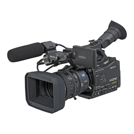
Photo: HVR-Z7U
RMT-831
US Model
Canadian Model
AEP Model
E Model
Chinese Model
Japanese Model
REPAIR PARTS LIST
ADJUSTMENTS
INSTRUCTION MANUAL
Published by Kohda TEC
2009B0500-1
© 2009.2
Advertisement
Table of Contents

Related Manuals for Sony HVR-Z7J


Summary of Contents for Sony HVR-Z7J
- Page 1 HVR-Z7J / Z7U / Z7N / Z7E / Z7P / Z7C RMT-831 SERVICE MANUAL US Model Ver. 1.5 2009.02 Canadian Model AEP Model Revision History Revision History E Model Revised-2 Chinese Model Japanese Model Replacement of the previously issued SERVICE MANUAL 9-852-265-14 with this manual.
- Page 2 Approx. 18.812 mm/s (w/h/d) **Still image resolution is obtained by the Tape speed (DVCAM) including the projecting parts with the unique pixel array of Sony’s ClearVid Approx. 28.218 mm/s battery pack (NP-F570) CMOS Sensor and image processing Tape speed (DV SP) Mass (approx.)
- Page 3 (w/h/d) Approx. 18.812 mm/s **Still image resolution is obtained by the including the projecting parts with the Tape speed (DVCAM) unique pixel array of Sony’s ClearVid battery pack (NP-F570) Approx. 28.218 mm/s CMOS Sensor and image processing Mass (approx.) Tape speed (DV SP) system (new Enhanced Imaging Approx.
- Page 4 852 x 3[RGB] x 480 LANC 6.0mm 1/3 3CMOS ø 2.5mm LENS INPUT1/ XLR3 ** 1440 810 HDV/ INPUT2 -48dBu 3k DV 16 9 +4dBu 10k 16 9 0dBu=0.775Vrms HDV/DV i.LINK IEEE1394 6 S100 16 9 HVR-Z7J/Z7U/Z7N/Z7E/Z7P/Z7C — 4 —...
- Page 5 Model information table Model HVR-Z7J HVR-Z7U HVR-Z7N HVR-Z7E HVR-Z7P HVR-Z7C Destination US, CND Color system NTSC NTSC NTSC • Abbreviation AR : Argentine model AUS : Australian model BR : Brazilian model CH : Chinese model CND : Canadian model...
- Page 6 CRITIQUES POUR LA SÉCURITÉ DE FONCTIONNEMENT. NE COMPONENTS WITH SONY PARTS WHOSE PART NUMBERS REMPLACER CES COMPOSANTS QUE PAR DES PIÈSES SONY APPEAR AS SHOWN IN THIS MANUAL OR IN SUPPLEMENTS DONT LES NUMÉROS SONT DONNÉS DANS CE MANUEL OU PUBLISHED BY SONY.
- Page 7 ENGLISH JAPANESE ENGLISH JAPANESE • • • • • • • • HVR-Z7J/Z7U/Z7N/Z7E/Z7P/Z7C — 7 —...
- Page 8 1) Select page: 0, address: 01, and set data: 01. 2) Select page: A, address: 10, set data: 00 and press the “PAUSE (Write) ” button of the adjustment remote commander. 3) Select page: 0, address: 01, and set data: 00. HVR-Z7J/Z7U/Z7N/Z7E/Z7P/Z7C...
- Page 9 C : Corrected by customer Indicates the appropriate Refer to “1-5-3. Self-diagnosis Code Table”. H : Corrected by dealer step to be taken. E : Corrected by service E.g. engineer 31 ..Reload the tape. 32 ..Turn on power again. HVR-Z7J/Z7U/Z7N/Z7E/Z7P/Z7C...
- Page 10 (IC2001 on the LG-005 board). Remove the lens block, battery or power cable, connect, and Bayonet mount fault perform oprations from the beginning. If it does not recover, inspect the cathode of D1001 to D1005 on the LG-005 board (ten places). HVR-Z7J/Z7U/Z7N/Z7E/Z7P/Z7C...
- Page 11 LG-005 board. (Note) If an error occurs again, replace the lens block. Note: When replacing the LG-005 board, remove the EEPROM (IC6005) from the LG-005 board that is going to be repaired. Install the removed EEPROM (IC6005) to the replaced LG-005 board. HVR-Z7J/Z7U/Z7N/Z7E/Z7P/Z7C...
- Page 12 3 Select page: A, address: 99, set data: 01 and press the “PAUSE (Write) ” button of the adjustment remote commander. 4 Select page: 0, address: 01, and set data: 00. 5 Check that “60i/50i SEL” is displayed in the “OTHERS” of the “MENU” on the LCD screen. TT-007 BOARD (SIDE A) CN1011 FP-760 FLEXIBLE BOARD (A-1539-015-A) LCD screen HVR-Z7J/Z7U/Z7N/Z7E/Z7P/Z7C...
- Page 13 ENGLISH JAPANESE ENGLISH JAPANESE 1. SERVICE NOTE HVR-Z7J/Z7U/Z7N/Z7E/Z7P/Z7C...
- Page 14 ENGLISH JAPANESE ENGLISH JAPANESE CPC-13 (J-6082-443-A) C : 3 1 : 1 1 HVR-Z7J/Z7U/Z7N/Z7E/Z7P/Z7C...
- Page 15 ENGLISH JAPANESE ENGLISH JAPANESE ws wf HVR-Z7J/Z7U/Z7N/Z7E/Z7P/Z7C...
- Page 16 ENGLISH JAPANESE ENGLISH JAPANESE qs qf qk wa qg qj HVR-Z7J/Z7U/Z7N/Z7E/Z7P/Z7C...
- Page 17 ENGLISH JAPANESE ENGLISH JAPANESE CN1011 HVR-Z7J/Z7U/Z7N/Z7E/Z7P/Z7C 1-10E...
- Page 18 It is possible that a wire is snapped. NOTE FOR DISCONNECTING THE HARNESS (COAXIAL CABLE) When disconnecting the harness (coaxial cable), do not pull the harness part but pull off the connector body with tweezers etc. Harness (Coaxial Cable) Tweezers etc. HVR-Z7J/Z7U/Z7N/Z7E/Z7P/Z7C...
- Page 19 ⋅ TT-007 Board ⋅ LCD Block 2-2-4. LCD SECTION 2-2-8. MS/ENG SECTION ⋅ Hinge Block ⋅ OO-006 Board ⋅ LCD ⋅ WW-005 Board ⋅ ENG Assy (LL-014 Board) 2-2-9. BT PANEL SECTION ⋅ Lens Mount Block ⋅ BT Panel Block HVR-Z7J/Z7U/Z7N/Z7E/Z7P/Z7C...
- Page 20 1 Lens Block (1-1) 2 Handle Block (2-1 to 2-14) (#49) 2-14 (#119) 2 Handle Block (See Page 2-4) 2-13 (#119) (Claw) (#49) 2-10 2-12 2-2 (#49) 2-11 (Claw) Overall Section-2 1-1 (Up) (See Page 2-7) 2-1 (#119) 1 Lens Block HVR-Z7J/Z7U/Z7N/Z7E/Z7P/Z7C...
- Page 21 Follow the disassembly in the numerical order given. 1 Handle Cabinet (Upper) (1-1 to 1-3) 2 EVF Block (2-1 to 2-5) 1 Handle Cabinet (Upper) 2 EVF Block 1-2 (#49) 1-1 (#49) 2-5 (#49) 2-1 (#49) 2-4 (#49) Handle Section-2 (See Page 2-5) HVR-Z7J/Z7U/Z7N/Z7E/Z7P/Z7C...
- Page 22 1 ZZ-005 Board (1-1 to 1-14) 2 LCD Block (2-1 to 2-3) 1-4 (#49) 2-1 (#119) 1 ZZ-005 Board 2 LCD Block 1-12 (#50) (See Page 2-6) HELP 1 1-13 1-14 HELP 1 HELP 1 1-11 1-10 1-3 (#53) 2-2 (#49) 1-1 (#49) HVR-Z7J/Z7U/Z7N/Z7E/Z7P/Z7C...
- Page 23 Follow the disassembly in the numerical order given. 1 Hinge Block (1-1 to 1-10) 2 LCD (2-1 to 2-8) 1 Hinge Block HELP 2 1-9 (#49) 1-10 1-2 (Claw) 1-1 (#49) 2-3 (#50) (#50) - 0 0 2 LCD (Claw) 1-7 (Claw) (#49) 1-6 (Claw) HVR-Z7J/Z7U/Z7N/Z7E/Z7P/Z7C...
- Page 24 3 Cabinet (R) (3-1 to 3-4) 2-2 (#49) 2-3 (#49) 2 Cabinet (L) 2-4 (Open) MD/Jack Section (See Page 2-8) (#49) 3 Cabinet (R) 3-1 (#49) (#49) 2-1 (#49) 2-5 (Open) 1 Bottom Cabinet 1-4 (Claw) 3-3 (#49) 1-3 (#49) 1-1 (#119) HVR-Z7J/Z7U/Z7N/Z7E/Z7P/Z7C...
-
Page 25: Mechanism Deck
Follow the disassembly in the numerical order given. 1 Mechanism Deck (1-1 to 1-10) 2 Jack Board (2-1 to 2-7) 2-5 (#50) 2-6 (Claw) 1 Mechanism Deck 2 Jack Block (Claw) 1-10 2-2 (#50) (#50) 1-1 (#50) 1-9 (#15) Main Board Section (See Page 2-9) HVR-Z7J/Z7U/Z7N/Z7E/Z7P/Z7C... - Page 26 1-10 HELP 6 1-13 1-11 (Claw) 1-14 1-15 (#50) HELP 5 - 0 0 MS/ENG Section (See Page 2-10) 1-4 (Note) HELP 4 1-3 (Note) HELP 3 Note: Refer to page 2-1 “Note for disconnecting the harness (coaxial cable)”. HVR-Z7J/Z7U/Z7N/Z7E/Z7P/Z7C...
- Page 27 1 OO-006 Board (1-1) 2 WW-005 Board (2-1 to 2-2) 3 ENG ASSY (LL-014 Board) (3-1) 1 OO-006 Board 1-1 (#50) 2 WW-005 Board 2-1 (#50) 3-1 (#50) 3 ENG ASSY 2-2 (Claw) (LL-014 Board) BT Panel Section (See Page 2-11) HVR-Z7J/Z7U/Z7N/Z7E/Z7P/Z7C 2-10...
- Page 28 1 Lens Mount Block (1-1 to 1-10) 2 BT Panel Block (2-1 to 2-4) 2 BT Panel Block (#49) 1-6 (#119) 1-4 (Claw) 1-8 (#120) 2-1 (#49) 1-9 (#120) 1-1 (#50) 2-2 (#49) 1-10 (#120) 1-2 (#50) 1 Lens Mount Block HVR-Z7J/Z7U/Z7N/Z7E/Z7P/Z7C 2-11E...
- Page 29 HELP 1: PR-074/SW-116/Speaker Harness PR-074 SW-116 Speaker Harness HELP 2: HELP 3: SW-116 Harness TAPE ASX2 TAPE ASX2 Panel Hinge Cabinet (B) SW-116 TAPE ASX2 Lens Mount TT-007 Harness Note: Harness must not run aground on the lens mount. HVR-Z7J/Z7U/Z7N/Z7E/Z7P/Z7C HELP...
- Page 30 HELP 4: Battery Terminal Board Harness Battery Terminal Board Harness HELP 5: HELP 6: FP-767 Flexible Board FP-770 Flexible Board FP-770 Flexible Board FP-767 Flexible Board HVR-Z7J/Z7U/Z7N/Z7E/Z7P/Z7C HELP...
-
Page 31: Block Diagrams
OVERALL BLOCK DIAGRAM (11/11) OVERALL BLOCK DIAGRAM (4/11) POWER BLOCK DIAGRAM (1/4) OVERALL BLOCK DIAGRAM (5/11) POWER BLOCK DIAGRAM (2/4) OVERALL BLOCK DIAGRAM (6/11) POWER BLOCK DIAGRAM (3/4) POWER BLOCK DIAGRAM (4/4) OVERALL BLOCK DIAGRAM (7/11) OVERALL BLOCK DIAGRAM (8/11) HVR-Z7J/Z7U/Z7N/Z7E/Z7P/Z7C... - Page 32 D24A00_IC_4401 - D31A07_IC_4401 CK64FSO CK64FSO DXXA08_IC_4401, DXXA09_IC_4401 CKFSO CKFSO CK_IC_2201_I SD_OSD_VD OVERALL (6/11) IC_2201_VF_SYNC AC14 (PAGE 3-6) XCS_IC_1801_IC_4401 AUIN21 AC15 XRST_VTR OVERALL (5/11) AUIN22 IC_1801_OEREF (PAGE 3-5) ADATAIN0 AB16 VREF ADATAIN1 AE15 : VIDEO SIGNAL CK27MFO1 : AUDIO SIGNAL HVR-Z7J/Z7U/Z7N/Z7E/Z7P/Z7C...
- Page 33 FOCUS RESET IC_2001/IC_3001_CK IC1503 SENSOR IC_4003_CK BUFFER GY-005 BOARD (8/8) F_GMR_A, F_GMR_B F_MR_A, F_MR_B CN8501 CN4001 SE8501 SHIFT_Y_OUT YAW_AD_IC_4003 PITCH_AD PITCH SENSOR SHIFT_P_OUT PITCH_AD_IC_4003 ACTIVE LENS ACTUATOR SHIFT_P_DRIVE+, IC8501 SE8502 YAW_AD SHIFT_P_DRIVE- P_DRIVE_A, P_DRIVE_B YAW SENSOR PITCH/ PITCH SENSOR DATA HVR-Z7J/Z7U/Z7N/Z7E/Z7P/Z7C...
- Page 34 XFTR_NR XFTR_NR (PAGE 3-7) MS_UPDATE_SW XLENS_IO_CTRL HI_SO, XHI_SCK HI_SI, HI_SO, XHI_SCK R_HOT LENS_DET_SW_M LENS_DET_SW_M XCS_CAMERA XCS_CAMERA PT_S ND_SW_AD ND_SW_AD Q1111, Q1112 LENS_DET_SW_E LENS DETECT OVERALL (6/11) IC4206 Q1110 NTSC/PAL_DET NTSC/PAL_DET NTSC/XPAL_DET_LG (PAGE 3-6) NTSC/PAL BUFFER DETECT (6/22) HI_SI_BO LENS_DET_SW_M HVR-Z7J/Z7U/Z7N/Z7E/Z7P/Z7C...
- Page 35 HSYNC VD_SI, VD_SO, XVDO VSYNC XVD_SCK UNIT EP_XHD DRIVE, DCLK EP_XVD XRST_VTR CONVERTER XCS_EVF_AD XCS_EVF_AD XCS_EVF XCS_EVF XCS_EVF VD_SI, VD_SO, VD_SO, OVERALL (6/11) VD_SI, VD_SO, XVD_SCK VD_SI, VD_SO, XVD_SCK VD_SCK XVD_SCK SI, SCK (PAGE 3-6) XRST_VTR XRST_VTR XRST_VTR RESET HVR-Z7J/Z7U/Z7N/Z7E/Z7P/Z7C...
- Page 36 OVERALL (1/11) HDV REC, DV REC HDV REC/PB, HDV-i.LINK RECDT (PAGE 3-1) ADATAIN1 ADATAIN1 EBS[0] - EBS[7] RECCK CK27MFO1 CK27MFO1 RECA1 CKFSO CKFSO AD17 RECA2 OVERALL (7/11) CK64FSO CK64FSO ERDY AD16 (PAGE 3-7) KCLK AD12 AD18 CKFSO CK64FSO ADATAIN0 ADATAIN1 HVR-Z7J/Z7U/Z7N/Z7E/Z7P/Z7C...
- Page 37 AB10 OVERALL (8/11) XRST_HDMI (PAGE 3-8) DIO, BS, SCLK MS_DIO, MS_BS, MS_SCLK MEMORY HDMI_SDA, HDMI_SCL IC3806 STICK CKE_VM 16M SDRAM XCS_SDRAM XMS_IN IC3804 (15/22) Q3601 32M FLASH OVERALL (11/11) XSYS_RST XCS_FLASH_VM XMS_LED_ON (15/22) (PAGE 3-11) DRIVE D8601 (MS ACCESS) HVR-Z7J/Z7U/Z7N/Z7E/Z7P/Z7C...
- Page 38 REC_PROOF REC_PROOF XREC_PROOF CHIME_SDA, CHIME_SDA, CHIME_SCL CHIME_SDA, CHIME_SCL CHIME_SDA, CHIME_SCK CHIME_SCK 4PIN CONNECTOR DD_SD1 S901 XCC_DOWN XCC_DOWN XCC_DOWN XCCDOWN_SW CC DOWN OVERALL (11/11) (PAGE 3-11) : VIDEO/AUDIO/SERVO SIGNAL FP-756 FLEXIBLE BOARD CN5002 : SERVO SIGNAL XEJECT_SW XEJECT_SW S101 (EJECT) HVR-Z7J/Z7U/Z7N/Z7E/Z7P/Z7C...
- Page 39 CONTROL SWITCH AUDIO D3103 KASYAON IN/OUT (19/22) XCS_IC_3101 OVERALL (6/11) KASYAON (PAGE 3-6) VSP_SO_BU, XVSP_SCK_BU XAU_MUTE1 XHP_MUTE XPWAD XCS_IC_3002 IC3004 ATT_1 IC_3004_RCK SHIFT ATT_2 REGISTER IC_3004_CLR (19/22) Q3001 OVERALL (7/11) IC_3004_ENABLE (PAGE 3-7) XCS_IC_3101 XCS_IC_3151 XCS_IC_5603 XCS_IC_5603 HP_JACK_IN HP_JACK_IN HVR-Z7J/Z7U/Z7N/Z7E/Z7P/Z7C...
- Page 40 INPUT 1 D_2.8V OVERALL (6/11) (PAGE 3-6) XLR_MIC/LINE_1 LINE MIC +48V XLR_PWR_ON_2 XLR_PWR_ON_2 XLR_PWR_ON_2 S001 INPUT 2 D_2.8V XLR_MIC/LINE_2 LINE S003 REC_CH_SEL REC_CH_SEL REC CH D_2.8V SELECT CH1 • CH2 CN7003 SP(±) SPOUT± SPOUT± SP901 OVERALL (8/11) SPEAKER (PAGE 3-8) HVR-Z7J/Z7U/Z7N/Z7E/Z7P/Z7C...
- Page 41 KEY_AD8 KEY_AD8-2 ASSIGN KEY_AD8-3 KEY_AD8-6 ZEBRA KEY_AD8-5 KEY_AD8-4 AE SHIFT REC VIEW S002 AUTO CH1_AUTO_MANUAL CH1_AUTO_MANUAL CH1_AUTO/MANUAL REC_LEVEL_VOL_CH1 REC_LEVEL_VOL_CH1 REC_LEVEL_VOL_CH1 REC_VOL_A/D_CH1 RV001 AUDIO LEVEL S004 AUTO CH2_AUTO_MANUAL CH2_AUTO_MANUAL CH2_AUTO/MANUAL OVERALL (7/11) (PAGE 3-7) REC_LEVEL_VOL_CH2 REC_LEVEL_VOL_CH2 REC_LEVEL_VOL_CH2 REC_VOL_A/D_CH2 RV002 HVR-Z7J/Z7U/Z7N/Z7E/Z7P/Z7C 3-10...
- Page 42 RESET VTR_DD_ON A_1.2V, D_1.2V, D_1.2V_K D_1.0V LI_3V LI_3V BT7001 XRESET LITHIUM EP_2.8V, D_2.8V, A_2.8V, D_2.5V, D_1.5V BATTERY CH4_4.6V, A_4.6V, AU_4.6V AU_5V, BL_5V, MT_5V, D4_-2.8V EP_1.8V, D_1.8V XRESET E_3.3V, D_3.3V LENS_5V LI_3V AU_8V, IC_5401_13.5V D4602 BL_-25V EVER_3.0V VOUT LANC_DC HVR-Z7J/Z7U/Z7N/Z7E/Z7P/Z7C 3-11...
- Page 43 XPUI_MODE_CAM_SW CAMERA OUT9-1 XLANC_PWR_ON XI_LANCPOWERON WAKE_UP XLANC_ON 16V_IN XO_LANCON XCTL2 R4714 XLR_UNREG Q4603 L4616 BL_-25V XO_SCK_DD SWITCHING FR_EVER_SO, FR_EVER_SCK O_SO_DD +INE10 BL_CONT BATT_IN -INE10 I_BATTIN CS_OUT XCS_DD1 OUT10-1 XO_CS_DD Q4601, Q4602 APPL_SW1, VTR_DD_ON EMERGENCY O_VTRDDON CH6_SW, DETECT CTL1 HVR-Z7J/Z7U/Z7N/Z7E/Z7P/Z7C 3-12...
- Page 44 NTSC/PAL (5/22) BUFFER BUFFER BUFFER XRST_VTR MULTIPLEXER (2/22) (6/22) (6/22) (6/22) XSYS_RST_LG (2/22) POWER (4/4) (PAGE 3-15) XSYS_RST XSYS_RST XRST_VTR XHIDS_RST CHIME_PWR_CONT XHDMI_DCIN XREEL_HALL_ON ENG_DD_ON MS_VCC_ON POWER (1/4) ENG_RST (PAGE 3-12) LENS_PWR_CTRL POWER (3/4) XSYS_RST (PAGE 3-14) XSYS_RST_LG HVR-Z7J/Z7U/Z7N/Z7E/Z7P/Z7C 3-13...
- Page 45 (6/8) E1 XRST DC/DC CONVERTER FOCUS MR F_GMR_VCC D2 XINIT ENG_RST SENSOR MF_SLIDE_LED F29 MF_SLIDE_LED Q1003 IR_RST_LED RST_IC4003 F_RST_VCC G29 N.C. FOCUS RESET MI_LED RST_IC_2001/IC_3001 SENSOR H28 N.C. VAP_DD_ON F_RST_LED VAP_DD_ON AH4 FC_RST_SENS MANUAL ZOOM Z_PT_VCC POTENTIO METER HVR-Z7J/Z7U/Z7N/Z7E/Z7P/Z7C 3-14...
- Page 46 BOARD CN6202 (BACK) R7811 L6201 EP_2.8V 3V(2.8V) EP_2.8V EP_1.8V FB6201 VDD(1.8V) VOUT FB6202 VDDIO(1.8V) LCD902 R1043 R7816 L6203 FB6203 1.8V EP_1.8V EP_2.8V VDDIO(3.0V) COLOR FB6204 VCC(3.0V) UNIT XRST_VTR XRST_VTR XRST_VTR XRST_VTR XRST_VTR XRST_VTR RESET POWER (2/4) (PAGE 3-13) HVR-Z7J/Z7U/Z7N/Z7E/Z7P/Z7C 3-15E...
- Page 47 FP-770 FLEXIBLE BOARD FLEXIBLE NN-005 Board BOARD YY-005 Board CN5001 CN6604 FP-767 FLEXIBLE BOARD (Page 4-2) (Page 4-2) WW-005 CN8602 FP-757 MEMORY STICK BOARD Flexible CONNECTOR Board OO-006 Board (Page 4-2) CN5603 CN8601 (Page 4-2) FLEXIBLE FLAT CABLE (FFC-112) HVR-Z7J/Z7U/Z7N/Z7E/Z7P/Z7C FRAME (1/2)
- Page 48 Flexible HEAD Board Board (Page 4-1) (Page 4-1) CN6604 CN6601 FP-228 M902 LOADING MOTOR FLEXIBLE BOARD FLEXIBLE FLAT CABLE (FFC-115) SS-182 BOARD (SIDE B) FP-767 CN7601 Flexible Board (Page 4-1) FP-031 FLEXIBLE BOARD N MECHANISM DECK (MDX-N231) HVR-Z7J/Z7U/Z7N/Z7E/Z7P/Z7C FRAME (2/2)
- Page 49 LL-014 BOARD TT-007 BOARD (14/22) (LENS CONNECTOR, DC/DC CONVERTER) (DS CONTROL, HI CONTROL) FP-766 FLEXIBLE BOARD TT-007 BOARD (15/22) (TT-LENS CONNECTION) (SDRAM, FLASH, EEPROM) FP-768 FLEXIBLE BOARD TT-007 BOARD (16/22) (TT-OO CONNECTION) (MECHA CONTROL) COMMON NOTE FOR SCHEMATIC DIAGRAMS HVR-Z7J/Z7U/Z7N/Z7E/Z7P/Z7C...
- Page 50 BB-010 BOARD (CONTROL SWITCH) (TT-II CONNECTION) WW-005 BOARD (MS CONNECTOR) CONTROL SWITCH BLOCK (GZ92000) SS-182 BOARD FP-765 FLEXIBLE BOARD (TT-NN CONNECTION) (SHOT TRANSITION/FOCUS MARKING) FP-031, FP-032, FP-228 FLEXIBLE BOARD NN-005 BOARD (1/3) (REC/PB AMP) (MECHANISM BLOCK) COMMON NOTE FOR SCHEMATIC DIAGRAMS HVR-Z7J/Z7U/Z7N/Z7E/Z7P/Z7C...
-
Page 51: Schematic Diagrams
In addition, ensure that the receiver is not covered with dusts nor exposed to strong light. Les composants identifiés par une marque 0 sont critiques pour la sécurité. Ne les remplacer que par une pièce portant le numéro spécifie. HVR-Z7J/Z7U/Z7N/Z7E/Z7P/Z7C... - Page 52 ENGLISH JAPANESE 4-2. SCHEMATIC DIAGRAMS ENGLISH JAPANESE 4-2. SCHEMATIC DIAGRAMS (JAPANESE) For PTB-450: Pattern box PTB-450 J-6082-200-A J-6020-250-A For PTB-1450: Small pattern box J-6082-559-A PTB-1450 J-6082-557-A L = 1 m (PTB-450) L = 40 cm (PTB-1450) Ω HVR-Z7J/Z7U/Z7N/Z7E/Z7P/Z7C...
- Page 53 R3017 1u B 0.1u D_SA_1.8V D_SA_1.8V C3016 C3034 1u B 0.1u EE-009 BOARD Note: EE-009 complete board and all mounted parts (including IC3001 (CMOS imager)) are not REG_GND CMOS IMAGER supplied, but they are included in PRISM device. HVR-Z7J/Z7U/Z7N/Z7E/Z7P/Z7C EE-009...
- Page 54 DOA6 R6032 DOA5 R6033 DOA4 R6034 R6011 DOA3 R6035 DOA2 R6036 CL6003 DOA1 R6037 DOA0 A_CP_PL_3.3V A_CP_PL_3.3V R6007 C6032 0.1u C6015 C6033 R6008 1u B 0.1u D_SA_1.8V D_SA_1.8V C6016 C6034 1u B 0.1u EE-010 BOARD REG_GND CMOS IMAGER HVR-Z7J/Z7U/Z7N/Z7E/Z7P/Z7C EE-010...
- Page 55 R1250 0 D_SC_1.8V DOB1 AD_G_B03 R1251 0 D_SA_1.8V D_1.8V_G DOB0 AD_G_B02 CN1202 20P D_DRV_1.8V D_2.8V_RGB C1222 LND122 D_DRV_1.8V SHASSI_GND REG_GND D_DRV_1.8V D_DRV_1.8V REG_GND D_DRV_1.8V D_1.8V_RGB_1 CN1205 30P TT-007 BOARD (1/22) REGULATOR XX MARK:NO MOUNT NO MARK:REC/PB MODE HVR-Z7J/Z7U/Z7N/Z7E/Z7P/Z7C TT-007 (1/22)
- Page 56 BIN_A02 AD_G_B02 BIN_A03 AD_G_B03 E3 H13 H9 AA10 P3 AA17 P7 J13 T1 AA2 U1 J14 AA20 U4 AA21 VDD 1.2V VDDSHV1 AFE I/O 2.8V TT-007 BOARD (2/22) CAMERA SIGNAL PROCESS XX MARK:NO MOUNT NO MARK:REC/PB MODE HVR-Z7J/Z7U/Z7N/Z7E/Z7P/Z7C TT-007 (2/22)
- Page 57 DQ10 SD_DQ10 VSSQ SD_DQ09 VSSQ SD_DQ08 SD_DQ07 VSSQ G8 G9 F7 F3 G1 G2 G3 H1 H2 J3 G7 H9 H3 J7 H8 R8 N7 R9 N8 P9 M8 M7 TT-007 BOARD (3/22) SDRAM XX MARK:NO MOUNT HVR-Z7J/Z7U/Z7N/Z7E/Z7P/Z7C TT-007 (3/22)
- Page 58 FB1801 D_2.8V C1806 D_2.8V CK27MFO1 6.3V D_2.5V FB1802 D_2.5V C1808 D_2.5V CK13MFO1 6.3V D_1.5V FB1803 D_1.5V D_1.5V L1804 10uH A_1.2V A_1.2V TT-007 BOARD (4/22) BASE BAND SIGNAL PROCESS 22uH L1805 A_2.8V 2012 XX MARK:NO MOUNT A_2.8V HVR-Z7J/Z7U/Z7N/Z7E/Z7P/Z7C TT-007 (4/22) 4-10...
- Page 59 R1128 4700 R1104 100k IN2+ IN3+ R1129 4700 IN2- IN3- ENG_ZM_POS R1130 OUT2 OUT3 R1123 R1131 100k IC1103 NJM3403AV(TE2) BUFFER C1108 0.1u ENG_ZM_POS_AD TT-007 BOARD (5/22) ENG_FC_POS_AD LENS-ENG LENS CONNECTION XX MARK:NO MOUNT NO MARK:REC/PB MODE HVR-Z7J/Z7U/Z7N/Z7E/Z7P/Z7C TT-007 (5/22) 4-11...
- Page 60 0.047u HI_SI_BO HI_SI_BO Tout DVCC AGND VREF XCS_SIO SE4201 XCS_CAMERA 3 AXIS AVCC XCS_LENS_SIO CAM_SO XCS_LENS_SIO HI_SO ACCELEROMETER Reserved1 LENS_SO LENS_SO TC74VHC126FT(EL) TT-007 BOARD (6/22) MS_UPDATE_SW CAMERA CONTROL 1 REG_GND XX MARK:NO MOUNT NO MARK:REC/PB MODE HVR-Z7J/Z7U/Z7N/Z7E/Z7P/Z7C TT-007 (6/22) 4-12...
- Page 61 AF17 AG17AF18 AG18AF19 AG19AF20 AG20AF21 AG21AF22 AG22AF23 AG23AF24 AG24AF25 AG25AF26 AG26AF27 AG27AE26 AE27 AD26AD27AC26 AC27 AB26 AB27 AA26 AA27 Y26 Y27 W26 W27 V26 V27 U26 U27 T26 T27 R26 R27 P26 P27 N26 N27 M26 L26 L27 K26 J26 J27 H26 G26 G27 F26 F27 E26 E27 D26 TT-007 BOARD (7/22) CAMERA CONTROL 2 HVR-Z7J/Z7U/Z7N/Z7E/Z7P/Z7C TT-007 (7/22) 4-13...
- Page 62 R2014 R2011 LINE_OUT_PR IC_1801_LNOPR Q2002 2SA2029T2LQ/R BUFFER R2002 ±0.5% R2015 R2012 LINE_OUT_C/PB IC_1801_LNOPB Q2003 2SA2029T2LQ/R BUFFER R2003 ±0.5% REG_GND C2001 A_2.8V C2002 FB2001 0.1u TT-007 BOARD (8/22) COMPONENT OUT AMP XX MARK:NO MOUNT NO MARK:REC/PB MODE HVR-Z7J/Z7U/Z7N/Z7E/Z7P/Z7C TT-007 (8/22) 4-14...
- Page 63 A1 F5 E4 C2 B1 G5 D2 E3 C1 F4 G4 D1 E2 F3 G3 E1 F2 G2 F1 G1 H5 H4 H1 H2 H3 J5 J1 J2 J3 J4 K1 K2 K3 K4 L1 L2 D_1.5V FB2801 VDD_1.5V_1 1.5V D_1.5V VDD_2.8V R2802 2.8V D_2.8V D_2.8V VDD_2.5V 2.5V D_2.5V C2801 FB2802 D_2.5V 2.2u B 6.3V REG_GND TT-007 BOARD (9/22) HDV INTERLACE/PROGRESSIVE CONVERTER XX MARK:NO MOUNT HVR-Z7J/Z7U/Z7N/Z7E/Z7P/Z7C TT-007 (9/22) 4-15...
- Page 64 B15 D15 E15 B14 D14 E14 A13 B13 D13 E13 A12 B12 D12 E12 A11 B11 D11 E11 A10 B10 D10 E10 C2206 L2201 C2203 C2204 C2205 C2201 4.7u 6.3V 6.3V 0.1u 6.3V 6.3V REG_GND C2220 D_1.0V TT-007 BOARD (10/22) D_2.5V/1.8V HDV-MPEG VIDEO ENCODE/DECODE A_1.0V A_1.0V XX MARK:NO MOUNT HVR-Z7J/Z7U/Z7N/Z7E/Z7P/Z7C TT-007 (10/22) 4-16...
- Page 65 E1 D1 C1 A1 B1 D2 C2 A2 B5 A5 C5 D5 G8 G9 F7 F3 G1 G2 G3 H1 H2 J3 G7 J7 H8 R8 N7 R9 N8 P9 M8 M7 L8 L2 TT-007 BOARD (11/22) SDRAM, FLASH XX MARK:NO MOUNT HVR-Z7J/Z7U/Z7N/Z7E/Z7P/Z7C TT-007 (11/22) 4-17...
- Page 66 D_1.5V D_1.5V IC_5201 R2603 D_1.2V C2603 C2605 4.7u C2604 C2607 4.7u C2606 0.1u 4.7u 0.1u 6.3V 6.3V 6.3V D_1.2V_K R2604 D_1.2V_K TT-007 BOARD (12/22) REG_GND C2601 C2602 4.7u 0.1u HDV STREAM PROCESS 6.3V XX MARK:NO MOUNT HVR-Z7J/Z7U/Z7N/Z7E/Z7P/Z7C TT-007 (12/22) 4-18...
- Page 67 B1 C3 D4 C1 C2 D2 D1 E5 E4 E1 E2 F5 F1 F2 G5 G1 F4 G2 H1 G4 H2 J1 H4 J2 K1 H5 L1 K2 R3409 6200 ±0.5% A_2.8V 10uH L3401 A_2.8V D_2.8V D_2.8V C3404 FB3401 4.7u 6.3V REG_GND C3415 C3401 0.1u 6.3V X3401 24.576MHz TT-007 BOARD (13/22) HDV/DV i.LINK INTERFACE XX MARK:NO MOUNT HVR-Z7J/Z7U/Z7N/Z7E/Z7P/Z7C TT-007 (13/22) 4-19...
- Page 68 P20 H14 H11 G12 G13 A21 B20 G11 L18 D21 B17 E21 C18 C16 B18 A19 B19 C19 C20 A18 D19 C17 A17 A16 B16 E20 C21 G15 F18 E18 C3611 C3612 0.1u 0.1u Q3609 DTC144EMT2L LED DRIVE TT-007 BOARD (14/22) DS CONTROL, HI CONTROL XX MARK:NO MOUNT NO MARK:REC/PB MODE HVR-Z7J/Z7U/Z7N/Z7E/Z7P/Z7C TT-007 (14/22) 4-20...
- Page 69 6.3V REG_GND R3811 D_2.8V C3801 R3802 0.1u 100k REG_GND 64K EEPROM AK6512CL-L IC3805 XCS_EEP XCS_EEP EEP_RXD3 HOLD EEP_RXD3 EEP_XRDY EEP_XRDY EEP_TXD3 EEP_TXD3 EEP_SCK3 EEP_SCK3 TT-007 BOARD (15/22) SDRAM, FLASH, EEPROM XX MARK:NO MOUNT NO MARK:REC/PB MODE HVR-Z7J/Z7U/Z7N/Z7E/Z7P/Z7C TT-007 (15/22) 4-21...
- Page 70 C4409 0.1u XHI_SCK XHI_SCK XCS_IC_4401 XCS_IC_4401 HI_SI HI_SI HI_SO HI_SO HDMI_SCL HDMI_SCL HDMI_SDA HDMI_SDA XCS_IC_3201 XCS_IC_3201 XRST_HDMI XRST_HDMI XSYS_RST XSYS_RST XCS_MC_FLASH XCS_MC_FLASH EEP_SI_S EEP_SI_S EEP_SO_S EEP_SO_S EEP_SCK_S EEP_SCK_S TT-007 BOARD (16/22) MECHA CONTROL XX MARK:NO MOUNT HVR-Z7J/Z7U/Z7N/Z7E/Z7P/Z7C TT-007 (16/22) 4-22...
- Page 71 A1 A2 A3 A4 A5 A6 A7 A8 A9 A10 A11 A12 B1 B2 B3 B4 B5 B6 B7 B8 B9 B10 B11 B12 C1 C2 C3 C4 C5 C6 C7 C8 C3209 0.1u TT-007 BOARD (17/22) HDMI SIGNAL PROCESS XX MARK:NO MOUNT HVR-Z7J/Z7U/Z7N/Z7E/Z7P/Z7C TT-007 (17/22) 4-23...
- Page 72 ADAO1_HDMI FS_HDMI 5V REG FS_HDMI ST_UNREG 64FS_HDMI 64FS_HDMI XHDMI_DICN R3328 XX D_2.8V R3329 XX C3311 0.22u C3308 C3309 C3310 0.22u 0.01u B 16V B 25V TT-007 BOARD (18/22) HDMI OUT XX MARK:NO MOUNT NO MARK:REC/PB MODE HVR-Z7J/Z7U/Z7N/Z7E/Z7P/Z7C TT-007 (18/22) 4-24...
- Page 73 2SD1834-T100 3.3V REG R3106 R3109 C3128 10 11 12 0.01u C3131 SPOUT+ SPOUT- C3123 0.01u REG_GND REG_GND S_C_OUT S_C_I/O VIDEO_OUT VIDEO_I/O S_Y_OUT S_Y_I/O TT-007 BOARD (19/22) VIDEO OUT, AUDIO IN/OUT XX MARK:NO MOUNT NO MARK:REC/PB MODE HVR-Z7J/Z7U/Z7N/Z7E/Z7P/Z7C TT-007 (19/22) 4-25...
- Page 74 R4031 IC_4401_SCK0 R4004 IC_4401_SCK0 IC_4401_RXD0 IC_4401_RXD0 IC_4401_TXD0 IC_4401_TXD0 R4032 XHIDS_RST XHIDS_RST 0.01u IC_4401_XCS0 C4004 IC_4401_XCS0 OSD_V OSD_V R4007 XFUPSTAT XFUPSTAT XHIDSCON_MAD XHIDSCON_MAD X4001 32.768kHz MULTI_JACK_IN C4005 C4006 MULTI_JACK_IN TT-007 BOARD (20/22) HI CONTROL XX MARK:NO MOUNT HVR-Z7J/Z7U/Z7N/Z7E/Z7P/Z7C TT-007 (20/22) 4-26...
- Page 75 R4620 A_4.6V R4616 150k Q4602 BL_CONT UNR91ABG08S0 DD_VREF R4619 DD_SD1 Q4601 UNR92A3G08S0 TT-007 BOARD (21/22) Q4601, Q4602 EMERGENCY DETECT DC/DC CONVERTER XX MARK:NO MOUNT NO MARK:REC/PB MODE ∗:IMPOSSIBLE TO MEASURE THE VOLTAGE AT THE MARKED POINTS. HVR-Z7J/Z7U/Z7N/Z7E/Z7P/Z7C TT-007 (21/22) 4-27...
- Page 76 TXC+ EEP_SO_S EEP_SO_S TMDS CLOCK- TXC- R1036 EEP_SCK_C EEP_SCK_C R1037 EEP_SCK_S EEP_SCK_S D_2.8V D_2.8V MD2_C MD2_C +5V POWER +5V POWER XCS_MC_FLASH_C XCS_MC_FLASH_C XCS_MC_FLASH XCS_MC_FLASH REG_GND XSYS_RST XSYS_RST LD1001 SHASSI_GND TT-007 BOARD (22/22) CONNECTOR XX MARK:NO MOUNT HVR-Z7J/Z7U/Z7N/Z7E/Z7P/Z7C TT-007 (22/22) 4-28...
- Page 77 MF_PT_VSS MF_P_VSS LG-005 BOARD (1/8) LENS DRIVE BLOCK is replaced as block (lens complete assy (SERVICE)), so that there PRINTED WIRING BOARD LENS CONNECTOR and SCHEMATIC DIAGRAM are omitted. NO MARK:REC/PB MODE R:REC MODE P:PB MODE HVR-Z7J/Z7U/Z7N/Z7E/Z7P/Z7C LG-005 (1/8) 4-29...
- Page 78 M1 K3 K4 M2 L3 J5 M3 L4 M4 K5 L5 M5 K6 L6 M6 J6 J7 M7 L7 K7 M8 L8 K8 M9 L9 M10 J8 L10 M11 K9 J9 L11 D_2.8V FB2001 D_2.8V C2008 C2011 C2014 0.1u 0.1u REG_GND MT_5V L2001 10uH MT_5V C2006 C2007 22u 10V MT_GND C2004 0.1u ZM_DRV_PWM ZM_DRV_ON ZM_DRV_BR LG-005 BOARD (2/8) LENS DRIVE XX MARK:NO MOUNT NO MARK:REC/PB MODE HVR-Z7J/Z7U/Z7N/Z7E/Z7P/Z7C LG-005 (2/8) 4-30...
- Page 79 M1 K3 K4 M2 L3 J5 M3 L4 M4 K5 L5 M5 K6 L6 M6 J6 J7 M7 L7 K7 M8 L8 K8 M9 L9 M10 J8 L10 M11 K9 J9 L11 D_2.8V FB3001 D_2.8V C3010 C3011 0.1u REG_GND MT_5V R3032 MT_5V C3004 C3005 MT_GND LG-005 BOARD (3/8) LENS DETECT XX MARK:NO MOUNT HVR-Z7J/Z7U/Z7N/Z7E/Z7P/Z7C LG-005 (3/8) 4-31...
- Page 80 P_DRIVE_A P_DRIVE_B Y_DRIVE_A Y_DRIVE_B REG_GND PITCH_HALL+ PITCH_AD_IC_4003 L4003 A_2.8V 10uH P_DRIVE_A A_2.8V P_DRIVE_B C4040 C4041 Y_DRIVE_A 0.1u Y_DRIVE_B REG_GND YAW_HALL+ YAW_AD_IC_4003 LG-005 BOARD (4/8) OIS DRIVE XX MARK:NO MOUNT NO MARK:REC/PB MODE R:REC MODE P:PB MODE HVR-Z7J/Z7U/Z7N/Z7E/Z7P/Z7C LG-005 (4/8) 4-32...
- Page 81 OUT1A I_DRIVE_A- MVCC2 0.1u OUT3A C3 C2 C1 D3 D1 E2 E3 E1 E4 F1 F2 G1 G2 C5014 0.01u R5015 B 25V XRST_IC_2001/IC_3001 LD_SCK XCS_SIO_LD LD_SO LD_SI LG-005 BOARD (5/8) IRIS DRIVE XX MARK:NO MOUNT HVR-Z7J/Z7U/Z7N/Z7E/Z7P/Z7C LG-005 (5/8) 4-33...
- Page 82 AJ1 AJ2 AJ3 AH3 AH4 AJ4 AJ5 AH5 AJ6 AH6 AJ7 AH7 AJ8 AH8 AG8 AG10AG12AG14 AJ9 AH9 AJ10 AH10AJ11 AH11AJ12 AH12AJ13 AH13AJ14 AH14AJ15 AH15AJ16 AH16AJ17 AH17AJ18 AH18AH19AJ19 AJ20 AH20AJ21 AH21AJ22 AH22AJ23 AH23AJ24 AJ25 AJ26 AJ27 AH24AH25AH26AH27AH29AJ29 EEP_SI EEP_SI IC_2001_SCK EEP_SO IC_2001_SCK EEP_SO EEP_SCK LD_SCK EEP_SCK LD_SCK XCS_SIO_LD XCS_SIO_LD XRST_IC_4003_CPU XRST_IC_4003_CPU C6015 XRST_IC_2001/IC_3001 XRST_IC_2001/IC_3001 IR_RST_SENS IR_RST_SENS FC_RING_SW FC_RING_SW ZM_M/S_SW ZM_M/S_SW LG-005 BOARD (6/8) CAMERA CONTROL 1 XX MARK:NO MOUNT NO MARK:REC/PB MODE HVR-Z7J/Z7U/Z7N/Z7E/Z7P/Z7C LG-005 (6/8) 4-34...
- Page 83 AF17 AG17AF18 AG18AF19 AG19AF20 AG20AF21 AG21AF22 AG22AF23 AG23AF24 AG24AF25 AG25AF26 AG26AF27 AG27AE26 AE27 AD26AD27AC26 AC27 AB26 AB27 AA26 AA27 Y26 Y27 W26 W27 V26 V27 U26 U27 T26 T27 R26 R27 P26 P27 N26 N27 M26 L26 L27 K26 J26 J27 H26 G26 G27 F26 F27 E26 E27 D26 LG-005 BOARD (7/8) CAMERA CONTROL 2 HVR-Z7J/Z7U/Z7N/Z7E/Z7P/Z7C LG-005 (7/8) 4-35...
- Page 84 (Page 4-59) 6.3V ZOOM_SW_AD ZOOM_SW_AD L1504 22uH D_2.8V D_2.8V A_2.8V C1510 C1512 X1501 6.3V 27MHz C1511 0.1u REG_GND BUFFER IC1503 C1508 HD74ALVC2G34USE-E 0.1u IC_2001/IC_3001_CK R1536 R1535 IC_4003_CK LG-005 BOARD (8/8) REGULATOR XX MARK:NO MOUNT NO MARK:REC/PB MODE HVR-Z7J/Z7U/Z7N/Z7E/Z7P/Z7C LG-005 (8/8) 4-36...
- Page 85 0.1u R8530 R8525 R8524 C8522 6.3V R8517 R8510 R8515 R8512 ±0.5% ±0.5% C8508 C8509 C8518 0.047u C8504 0.1u C8505 R8513 0.1u 0.33u C8515 ±0.5% 0.1u C8501 6.3V GY-005 BOARD PITCH/YAW SENSOR XX MARK:NO MOUNT NO MARK:REC/PB MODE HVR-Z7J/Z7U/Z7N/Z7E/Z7P/Z7C GY-005 4-37...
- Page 86 REG_GND ZOOM POSITION R6418 REG_GND FOCUS POSITION (RESERVE) R6408 R6419 (RESERVE) LENS VD4601 LND461 SHASSI_GND VD4602 VD4604 VD4607 VD4610 VD4605 VD4608 VD4611 VD4603 VD4606 VD4609 LL-014 BOARD LENS CONNECTOR, DC/DC CONVERTER XX MARK:NO MOUNT NO MARK:REC/PB MODE HVR-Z7J/Z7U/Z7N/Z7E/Z7P/Z7C LL-014 4-38...
- Page 87 LND102 LND051 ATT_1 ATT_1 LND101 51Pin 1Pin TT-007 OO-006 (22/22) CN5603 (Page 4-40) CN1006 (Page 4-28) FP-768 FLEXIBLE BOARD FP-766 FLEXIBLE BOARD TT-OO CONNECTION TT-LENS CONNECTION (PRINTED WIRING BOARD is omitted.) (PRINTED WIRING BOARD is omitted.) HVR-Z7J/Z7U/Z7N/Z7E/Z7P/Z7C FP-766, FP-768 4-39...
- Page 88 SWITCHING XCS_IC_5603 XCS_IC_5603 R5772 D5753 VSP_SO VSP_SO AU_+8V ATT_2 ATT_2 R5773 Q5755 ATT_1 ATT_1 REG_GND REG_GND A_GND D5756 MA4ZD03001S0 C5768 D4_-2.8V 0.22u AU_-10V REG_GND CHISSIS_GND LND562 OO-006 BOARD AUDIO LEVEL CONTROL XX MARK:NO MOUNT NO MARK:REC/PB MODE HVR-Z7J/Z7U/Z7N/Z7E/Z7P/Z7C OO-006 4-40...
- Page 89 REG_GND Y_GND D3_LNO_PB R8210 REG_GND D3_LNO_PR PRPB_GND R8211 REG_GND COMPONENT R8212 LINE_CNT1 CTRL1 R8213 CTRL2 LINE_CNT2 R8214 CTRL3 LINE_CNT3 R8215 SW_GND D3CN REG_GND D8202 LND822 REG_GND CHASSIS_GND NSAD500H-T1-A JJ-005 BOARD LANC, A/V, COMPONENT CONNECTOR XX MARK:NO MOUNT HVR-Z7J/Z7U/Z7N/Z7E/Z7P/Z7C JJ-005 4-41...
- Page 90 REG_GND LND104 REG_GND LND049 SIRCS_SIG_FRONT SIRCS_SIG_FRONT LND103 REG_GND REG_GND LND102 LND050 LND051 REG_GND LND101 REG_GND 51Pin 1Pin TT-007 FP-767 FLEXIBLE BOARD YY-005 (22/22) CN6604 CN1003 (Page 4-43) (Page 4-28) TT-YY CONNECTION (PRINTED WIRING BOARD is omitted.) HVR-Z7J/Z7U/Z7N/Z7E/Z7P/Z7C FP-767, FP-770 4-42...
- Page 91 PLRE PANEL_R XF_TALLY_LED REG_GND XF_TALLY_LED EXEC_LED EXEC_LED REG_GND XBATT_INFO_SW REG_GND XBATT_INFO_SW REG_GND REG_GND EXEC_LED EXEC_LED CHECK_LED CHECK_LED STORE_LED STORE_LED A_4.6V A_4.6V LI_3V LI_3V LI_3V REG_GND LND661 CHISSIS_GND REG_GND SIRCS_SIG_FRONT SIRCS_SIG_FRONT REG_GND REG_GND REG_GND YY-005 BOARD RELAY CONNECTOR HVR-Z7J/Z7U/Z7N/Z7E/Z7P/Z7C YY-005 4-43...
- Page 92 YY-005 ZZ-005 CN6603 CN7004 (Page 4-43) (Page 4-45) FP-773 FLEXIBLE BOARD YY-ZZ CONNECTION (PRINTED WIRING BOARD is omitted.) HVR-Z7J/Z7U/Z7N/Z7E/Z7P/Z7C FP-773 4-44...
- Page 93 HOLDER VDR701 BT7001 LITHIUM BATTERY LND701 SHASSI_GND_C REG_GND ZZ-005 BOARD Note: BT7001 (lithium battery) is not included in ZZ-005 complete board. XX-016 PANEL RELAY CONNECTOR CN5801 Through the Flexible Flat Cable NO MARK:REC/PB MODE (FFC-116) (Page 4-58) HVR-Z7J/Z7U/Z7N/Z7E/Z7P/Z7C ZZ-005 4-45...
- Page 94 13.1 12.4 BL_H BL_H C6003 BL_H Q6001 12.4 R6012 R6014 DTA144EMT2L 4700 R6010 R6015 EXTDA CL6011 TCOM2 BL_CONT Q6003 TRANSISTORHN1B04FE-Y/GR(TPLR3) R6009 C6007 R6013 3300 ±0.5% PP-005 BOARD LCD DRIVE, A/D CONVERTER XX MARK:NO MOUNT NO MARK:REC/PB MODE HVR-Z7J/Z7U/Z7N/Z7E/Z7P/Z7C PP-005 4-46...
- Page 95 BODY_AD LND230 KEY_AD1 LND231 LND232 REG_GND LND233 REG_GND 33pin FP-77O FLEXIBLE LND040 – LND078 (Page 4-42) D201 REC LAMP (BACK) SML-310LTT86 R201 C201 4.7u R202 REMOTE SENSOR (BACK) FP-757 FLEXIBLE BOARD REMOTE SENSOR (BACK) NO MARK:REC/PB MODE HVR-Z7J/Z7U/Z7N/Z7E/Z7P/Z7C FP-757 4-47...
- Page 96 REG_GND EP_XHD D7802 C7805 EVF_R REG_GND EVF_G REG_GND EVF_B REG_GND R7818 REG_GND S7801 R7816 REG_GND EP_XVD EP_XHD LND781 R7819 REG_GND CHASSIS GND (HANDLE ZOOM) LND782 CHASSIS GND GG-005 BOARD RELAY CONNECTOR XX MARK:NO MOUNT NO MARK:REC/PB MODE HVR-Z7J/Z7U/Z7N/Z7E/Z7P/Z7C GG-005 4-48...
- Page 97 A1 A2 A3 A4 A5 A6 A7 A8 A9 A10 A11 A12 B12 C12 D12E12 F12 G12H12J12 4.7u XCS_EVF C6210 VD_SO C6211 R6213 C6215 XRST_VTR RESET C6223 VCC(3.0V) FB6204 0.1u VCC(3.0V) REG_GND C6214 C6227 0.047u 4.7u R6207 4700 ±0.5% C6212 C6213 2.2u 0.0047u 6.3V UU-005 BOARD EVF DRIVE, A/D CONVERTER XX MARK:NO MOUNT HVR-Z7J/Z7U/Z7N/Z7E/Z7P/Z7C UU-005 4-49...
- Page 98 1Pin TPA- TPA- TH8403 REG_GND TPB+ TH8404 HDV/DV TPB- REG_GND RB8401 TPB+ TPB- REG_GND REG_GND FP-772 FLEXIBLE LND841 (Page 4-51) CHASSIS_GND FP-776 FLEXIBLE BOARD II-005 BOARD UU-EVF CONNECTION HDV/DV CONNECTOR (PRINTED WIRING BOARD is omitted.) HVR-Z7J/Z7U/Z7N/Z7E/Z7P/Z7C FP-775, II-005, FP-776 4-50...
- Page 99 (Page 4-28) REG_GND REG_GND REG_GND REG_GND TPA+ TPA+ TPA- TPA- REG_GND REG_GND II-005 CN8401 REG_GND REG_GND (Page 4-50) TPB+ TPB+ TPB- TPB- REG_GND REG_GND REG_GND REG_GND 1PIN 22PIN FP-772 FLEXIBLE BOARD TT-II CONNECTION (PRINTED WIRING BOARD is omitted.) HVR-Z7J/Z7U/Z7N/Z7E/Z7P/Z7C FP-772 4-51...
- Page 100 R8605 XX XMS_IN MS_DIO MS_BS REG_GND LND862 REG_GND MS_LED_ON CHASSIS_GND D_2.8V R8601 680 D8601 TT-005 SML-310LTT86 (22/22) (MS ACCESS) CN1005 Through the Flexible Flat Cable (FFC-112) (Page 4-28) WW-005 BOARD MS CONNECTOR XX MARK:NO MOUNT NO MARK:REC/PB MODE HVR-Z7J/Z7U/Z7N/Z7E/Z7P/Z7C WW-005 4-52...
- Page 101 TT-007 NN-005 (22/22) (3/3) CN1001 CN5001 (Page 4-28) (Page 4-56) FP-765 FLEXIBLE BOARD TT-NN CONNECTION (PRINTED WIRING BOARD is omitted.) HVR-Z7J/Z7U/Z7N/Z7E/Z7P/Z7C FP-765 4-53...
- Page 102 37 38 39 40 41 42 43 44 45 46 47 48 C5205 0.1u A_2.8V SW_PS C5214 0.1u 75Hz RF SWP D8 75Hz CONT1 ALL_PS NN-005 BOARD (1/3) REC/PB AMP NO MARK:REC/PB MODE R:REC MODE P:PB MODE HVR-Z7J/Z7U/Z7N/Z7E/Z7P/Z7C NN-005 (1/3) 4-54...
- Page 103 10V B CAP_W CAP_W XCS_IC_5401 CAP_W XVSP_SCK CAP_W CK13MFO1 CAP_W XRST_VTR CAP_U UNLOAD CAP_U LOAD CAP_U LM_LIM_DET CAP_U CAP_U XFFREWUP N.C. FG_GND FG_GND REG_GND FG_VCC MR_VCC FG_VCC NN-005 BOARD (2/3) SERVO XX MARK:NO MOUNT NO MARK:REC/PB MODE HVR-Z7J/Z7U/Z7N/Z7E/Z7P/Z7C NN-005 (2/3) 4-55...
- Page 104 REG_GND (Page 4-57) VTR_UNREG MT_GND VTR_UNREG MT_GND REG_GND REG_GND VTR_UNREG MT_GND REG_GND REG_GND REG_GND (REG_GND)NC REG_GND REG_GND LND501 CHASSIS_GND REG_GND LND502 CHASSIS_GND LND503 CHASSIS_GND NN-005 BOARD (3/3) CAPSTAN/DRUM MOTOR DRIVE XX MARK:NO MOUNT NO MARK:REC/PB MODE HVR-Z7J/Z7U/Z7N/Z7E/Z7P/Z7C NN-005 (3/3) 4-56...
- Page 105 LND602 HP_R_OUT FB602 JJ-005 L_OUT LND603 HP_GND CN8201 FB603 R_OUT (HEADPHONES) HP_L_OUT LND604 (Page 4-41) LND605 HP_GND R601 R603 LND606 HP_JACK 1pin FP-486 FLEXIBLE BOARD FP-645 FLEXIBLE BOARD HEADPHONES JACK HDMI CONNECTOR XX MARK:NO MOUNT HVR-Z7J/Z7U/Z7N/Z7E/Z7P/Z7C FP-756, FP-486, FP-645 4-57...
- Page 106 CONTROL 100k XLR_PWR_ON_2 XLR_PWR_ON_2 Q5953 R5960 2SK3019TL R5971 Q5957 R5980 SWITCH 2SC6054GR8S0 REG_GND REG_GND Note: IC5952 is not supplied, but this is included in XX-016 complete board. XX-016 BOARD XLR INPUT XX MARK:NO MOUNT NO MARK:REC/PB MODE HVR-Z7J/Z7U/Z7N/Z7E/Z7P/Z7C XX-016 4-58...
- Page 107 REG_GND (SW-116) CH1 CH2 (Page 4-45) REC CH SELECT CONTROL SWITCH BLOCK (AS92000) HH-008 BOARD PANEL REVERSE DETECT CONTROL SWITCH BLOCK (AS92000) is replaced as block, as block,so that PRINTED WIRING BOARD is omitted. HVR-Z7J/Z7U/Z7N/Z7E/Z7P/Z7C LZ92000, AS92000, KK-032, HH-008 4-59...
- Page 108 SPEED LND010 KEY_AD3-2 LND007 KEY_AD5-1 S006 LND006 KEY_AD5-2 MENU LND016 REG_GND S004 1pin PICTURE PROFILE S003 STATUS CHECK CONTROL SWITCH BLOCK (RS92000) CONTROL SWITCH BLOCK (RS92000) is replaced as block, so that PRINTED WIRING BOARD is omitted. HVR-Z7J/Z7U/Z7N/Z7E/Z7P/Z7C RS92000 4-60...
- Page 109 ASSIGN AE SHIFT KEY_AD8-1 KEY_AD8-3 S017 20pin ZEBRA S002 AUTO AUDIO LEVEL AUTO S004 S021 S022 ASSIGN S023 CONTROL SWITCH BLOCK (PS92000) CONTROL SWITCH BLOCK (PS92000) is replaced as block, so that PRINTED WIRING BOARD is omitted. HVR-Z7J/Z7U/Z7N/Z7E/Z7P/Z7C PS92000 4-61...
- Page 110 REG_GND (Page 4-28) KEY_AD 8 KEY_AD 8 REG_GND A_2.8V REC_LEVEL_VOL_CH1 CH1_AUTO_MANUAL CH2_AUTO_MANUAL REC_LEVEL_VOL_CH2 REG_GND CN8003 CONTROL SWITCH BLOCK (PS92000) SHASSI_GND (Page 4-61) D8001 D8003 D8005 D8007 D8002 D8004 D8006 RR-005 BOARD TT-CONTROL SWITCH CONNECTION XX MARK:NO MOUNT HVR-Z7J/Z7U/Z7N/Z7E/Z7P/Z7C RR-005 4-62...
- Page 111 LND406 D_2.8V (Page 4-45) REC LAMP D401 LND407 (FRONT) F_TALLY_LED SML-310LTT86 LND408 SIRCS_SIG LND409 REG_GND C401 LND410 A_4.6V 4.7u 1pin RS-770 IC401 R402 REMOTE SENSOR (FRONT) FP-759 FLEXIBLE BOARD REMOTE SENSOR (FRONT), PANEL DETECT NO MARK:REC/PB MODE HVR-Z7J/Z7U/Z7N/Z7E/Z7P/Z7C FP-759 4-63...
- Page 112 3900 8200 KEY_AD2 PANEL_REVERSE REG_GND MEMORY(VCR) PAUSE PLAY INDEX DELETE R7202 R7204 R7207 R7210 R7213 R7217 1200 1500 2200 3900 8200 KEY_AD4 PANLE_OPEN REG_GND VOLUME MEMORY DATA CODE TC/U-BIT – LND722 SHASSI_GND_C REG_GND BB-010 BOARD CONTROL SWITCH HVR-Z7J/Z7U/Z7N/Z7E/Z7P/Z7C BB-010 4-64...
- Page 113 A_4.6V CN6601 D7603 Through the R7605 A_4.6V SML-D12D8WT86SQ 4700 Flexible Flat Cable D7602 R7603 STORE_LED (FFC-115) SML-D12D8WT86SQ 4700 D7601 (Page 4-43) CHECK_LED SML-D12D8WT86SQ EXEC_LED R7601 CHECK STORE REG_GND 4700 EXEC SHASSI_GND SS-182 BOARD SHOT TRANSITION/FOCUS MARKING HVR-Z7J/Z7U/Z7N/Z7E/Z7P/Z7C GZ92000, SS-182 4-65...
- Page 114 XMODE_SW_A TAPE TOP SENSOR XMODE_SW_B XMODE_SW_B FLEXIBLE XMODE_SW_C XMODE_SW_C SW_COM/SW_GND SW_COM/SW_GND BOARD H901 HW-105A-CDE-T MIC903 S REEL SENSOR S903 (MODE SWITCH) S902 (REC PROOF) 4 PIN H902 HW-105A-CDE-T CONNECTOR T REEL SENSOR FP-031 FLEXIBLE BOARD HVR-Z7J/Z7U/Z7N/Z7E/Z7P/Z7C FP-031, FP-032, FP-228 4-66...
- Page 115 OO-006 BOARD XX-016 BOARD JJ-005 BOARD KK-032 BOARD YY-005 BOARD HH-008 BOARD PP-005 BOARD RR-005 BOARD ZZ-005 BOARD BB-010 BOARD FP-757 FLEXIBLE BOARD SS-182 BOARD FP-759 FLEXIBLE BOARD FP-031, FP-032, FP-228 FLEXIBLE BOARD COMMON NOTE FOR PRINTED WIRING BOARDS HVR-Z7J/Z7U/Z7N/Z7E/Z7P/Z7C...
- Page 116 : pattern of the rear side (The other layers’ patterns are not indicated) • Through hole is omitted. • There are a few cases that the part printed on diagram isn’t mounted in this model. • C: panel designation (JAPANESE) HVR-Z7J/Z7U/Z7N/Z7E/Z7P/Z7C 4-67...
- Page 117 R6012 C6027 C6031 C6035 A_DAR_3.3V C6030 C6025 C6013 C6038 C6016 1-874-026- 1-874-026- CL6002 CL6003 D_SA_1.8V Note: EE-010 board and all mounted parts (including IC6001 (CMOS imager)) are not supplied, but they are included in PRISM device. HVR-Z7J/Z7U/Z7N/Z7E/Z7P/Z7C EE-009, EE-010 4-68...
- Page 118 R1232 R4613 R4612 R1231 R1230 C1119 R1229 LND122 R1228 R4668 R4649 F4604 F4603 C4670 C4652 C4649 L4616 F4609 C4706 L4622 C4651 C4660 D4612 D4613 C4663 R4640 C4664 C4650 C4659 IC4603 CN4601 CN1007 LND461 Q4614 1-873-230- HVR-Z7J/Z7U/Z7N/Z7E/Z7P/Z7C TT-007 (SIDE A) 4-69...
- Page 119 R1122 R1126 Q1102 R1131 R1123 L4625 R1110 R1037 R4678 C4693 R1036 R4635 C4645 R4664 R1129 Q1114 R1130 R1182 R1128 R1127 R4689 IC1103 C1111 R1178 R1160 R1169 C4705 C1113 R1164 C1112 R1161 IC1105 D1107 C1108 D1106 HVR-Z7J/Z7U/Z7N/Z7E/Z7P/Z7C TT-007 (SIDE B) 4-70...
- Page 120 E2 F2 G2 H2 J2 K2 L2 M2 C2015 D_1.8V A1 B1 C1 D1 E1 F1 G1 H1 J1 K1 L1 M1 R2013 C2016 R2012 R2007 C2002 R1534 D1005 C1001 L1001 C1507 R2009 D_2.8V C2001 1-873-486- HVR-Z7J/Z7U/Z7N/Z7E/Z7P/Z7C LG-005 (SIDE A) 4-71...
- Page 121 AE28 AD28 AC28 AB28 AA28 AJ29 AH29 AG29 AF29 AE29 AD29 AC29 AB29 AA29 R6030 C6010 C6017 R6033 FB6001 R6019 R6018 1-873-486- Note: IC6005 is not supplied, but this is included in LG-005 complete board. HVR-Z7J/Z7U/Z7N/Z7E/Z7P/Z7C LG-005 (SIDE B) 4-72...
- Page 122 ENG assy (SERVICE). C6409 C6404 C6421 R6401 R6404 LENS C6402 VD4603 R6411 R6402 VD4610 R6418 Q6401 VD4607 VD4602 R6409 R6415 VD4601 VD4611 R6408 R6419 VD4609 VD4606 R6417 R6414 VD4608 VD4604 R6416 R6412 L6402 L6401 1-874-082- 1-874-082- HVR-Z7J/Z7U/Z7N/Z7E/Z7P/Z7C GY-005, LL-014 4-73...
- Page 123 IC5752 R5779 C5766 R5705 Q5755 R5707 C5703 R5723 R5773 C5767 R5772 Q5756 R5706 R5710 C5702 R5708 R5724 C5754 C5705 R5701 R5709 R5758 R5752 C5753 C5755 R5756 Q5752 R5763 R5755 R5753 IC5751 R5764 Q5753 R5757 C5756 1-874-201- 1-874-201- HVR-Z7J/Z7U/Z7N/Z7E/Z7P/Z7C OO-006 4-74...
- Page 124 COMPONENT R8211 D8202 R8210 R8209 R8208 VDR824 R8205 VDR827 VDR825 R8207 D8205 R8204 D8206 R8206 A/V OUT D8204 R8203 FB8202 VDR826 FB8201 VDR828 R8220 R8219 R8218 R8202 D8201 R8217 FB8204 LANC CN8205 LND822 VDR821 VDR822 1-873-228- 1-873-228- HVR-Z7J/Z7U/Z7N/Z7E/Z7P/Z7C JJ-005 4-75...
- Page 125 C6021 C6008 C6022 CL6007 CL6006 EP_2.8V L6004 C6005 L6003 C6004 L6005 C6006 R6015 D6002 Q6004 R6014 CL6010 CL6009 CL6008 FB6001 C6003 R6008 C6029 C6031 Q6002 R6025 R6026 CL6011 R6025 R6011 C6027 C6028 CN6002 CN6003 CN6004 1-873-236- HVR-Z7J/Z7U/Z7N/Z7E/Z7P/Z7C YY-005, PP-005 4-76...
- Page 126 When mounting these parts, mount new battery CAUTION holder first and attach new lithium battery next. Danger of explosion if battery is incorrectly replaced. Replace only with the same or equivalent type. HVR-Z7J/Z7U/Z7N/Z7E/Z7P/Z7C ZZ-005 4-77...
- Page 127 1-873-714- FP-759 FLEXIBLE BOARD D201 R201 REC LAMP (BACK) C201 IC401 IC201 R401 REC LAMP (FRONT) S101 (EJECT) LND410 LND409 LND408 IC402 LND407 LND406 C403 LND405 LND404 LND403 LND402 LND401 1-783-716- FP-756 FLEXIBLE BOARD 1-873-713- HVR-Z7J/Z7U/Z7N/Z7E/Z7P/Z7C FP-757, FP-759, FP-756 4-78...
- Page 128 R7806 R7805 R7804 R7803 R7802 R7801 C7805 L6201 D7802 EP_1.8V C6204 R7818 LND781 1-873-235- 1-873-237- GG-005 BOARD (SIDE B) UU-005 BOARD (SIDE B) FB6201 C6221 C6206 C6219 C6207 R6213 1-873-235- C6223 C6227 C6213 FB6204 R6207 1-873-237- HVR-Z7J/Z7U/Z7N/Z7E/Z7P/Z7C GG-005, UU-005 4-79...
- Page 129 II-005 (2 layers), WW-005 (2 layers) : Uses unleaded solder. D8601 II-005 BOARD WW-005 BOARD (MS ACCESS) LND842 CN8401 CN8602 RB8401 TH8401 TH8402 LND862 HDV/DV TH8403 TH8404 LND841 1-873-234- C8603 C8602 C8601 CN8601 LND861 1-873-233- HVR-Z7J/Z7U/Z7N/Z7E/Z7P/Z7C II-005, WW-005 4-80...
- Page 130 26 27 C5419 76 77 96 25 24 R5410 11 16 19 23 22 C5418 C5407 R5409 13 15 18 20 66 VTR_UNREG HE_VCC D_2.8V C5003 C5008 C5004 C5007 IC5001 IC5002 R5001 R5002 C5005 C5006 CN5002 1-873-231- 1-873-231- HVR-Z7J/Z7U/Z7N/Z7E/Z7P/Z7C NN-005 4-81...
- Page 131 R5863 Q5959 C5865 R5907 R5910 R5912 R5932 L5901 C5974 C5917 R5911 R5924 INPUT 2 Q5903 Q5908 R5903 L5902 R5916 R5917 R5904 R5934 R5918 IC5901 R5933 R5902 R5915 Q5907 R5901 C5918 Q5904 R5923 R5935 1-874-291- 1-874-291- HVR-Z7J/Z7U/Z7N/Z7E/Z7P/Z7C FP-645, FP-486, XX-016 4-82...
- Page 132 : Uses unleaded solder. KK-032 BOARD RR-005 BOARD WHT BAL PRESET GAIN R8022 1-874-435- R8023 R8024 R8025 HH-008 BOARD (SIDE A) LD8001 CN7401 1-873-225- CN8001 CN8002 HH-008 BOARD (SIDE B) 1-873-610- S7401 PANEL REVERSE 1-873-225- HVR-Z7J/Z7U/Z7N/Z7E/Z7P/Z7C KK-032, HH-008, RR-005 4-83...
- Page 133 PLAY R7201 S7207 S7206 S7202 S7205 S7210 R7206 R7209 1-874-181- 1-874-181- SS-182 BOARD (SIDE A) SS-182 BOARD (SIDE B) SHOT TRANSITION/FOCUS MARKING R7602 R7604 S7601 S7602 S7603 LD7601 D7601 D7603 STORE EXEC D7602 1-874-180- CHECK 1-874-180- HVR-Z7J/Z7U/Z7N/Z7E/Z7P/Z7C BB-010, SS-182 4-84...
- Page 134 (REC PROOF) 4 PIN CONNECTOR 1-867-810- FP-228 FLEXIBLE BOARD H902 SENSOR T REEL SENSOR 1-677-049- 11 M902 LOADING MOTOR H901 S REEL SENSOR (Dilect Solder) (Dilect Solder) FP-031 FLEXIBLE BOARD 1-867-811- Q901 TAPE END SENSOR HVR-Z7J/Z7U/Z7N/Z7E/Z7P/Z7C FP-031, FP-032, FP-228 4-85E...
- Page 135 HANDLE SECTION-2 HANDLE SECTION-3 HANDLE SECTION-4 LCD SECTION MD/JACK SECTION OVERALL SECTION-2 CABINET (L) SECTION CABINET (R) SECTION MS/ENG SECTION MAIN BOARD SECTION BT PANEL SECTION LENS MOUNT SECTION MECHANISM DECK LS/MECHANICHAL CHASSIS LS/MECHANICHAL CHASSIS SECTION BLOCK ASSEMBLY-1 BLOCK ASSEMBLY-2 HVR-Z7J/Z7U/Z7N/Z7E/Z7P/Z7C...
- Page 136 II-005 BOARD TT-007 BOARD FP-228 FLEXIBLE BOARD JJ-005 BOARD UU-005 BOARD FP-486 FLEXIBLE BOARD KK-032 BOARD WW-005 BOARD XX-016 BOARD FP-645 FLEXIBLE BOARD LG-005 BOARD FP-756 FLEXIBLE BOARD LL-014 BOARD YY-005 BOARD FP-757 FLEXIBLE BOARD NN-005 BOARD ZZ-005 BOARD HVR-Z7J/Z7U/Z7N/Z7E/Z7P/Z7C...
-
Page 137: Repair Parts List
: Argentine model AUS : Australian model : Brazilian model : Chinese model CND : Canadian model : East European model HK : Hong Kong model : Japanese model : Tourist model : Korea model : North European model HVR-Z7J/Z7U/Z7N/Z7E/Z7P/Z7C... -
Page 138: Exploded Views
Lens Section (See Page 5-3) Ref. No. Part No. Description Ref. No. Part No. Description 3-288-534-01 CABINET (FRONT), HANDLE 2-630-005-31 SCREW (M2), NEW TRUSTER, P2 (Black) X-2188-603-1 CABINET (REAR) ASSY, HANDLE #119 7-627-556-58 SCREW +P 2.6X5 (Black) 3-288-398-01 CABINET (TOP) HVR-Z7J/Z7U/Z7N/Z7E/Z7P/Z7C... - Page 139 2-891-494-11 SCREW (M2), NEW TRUSTER, P2 (Red) 1-834-246-11 FLEXIBLE FLAT CABLE (FFC-118) #122 7-682-547-09 SCREW +B 3X6 (Black) A-1510-484-A GY-005 BOARD, COMPLETE (SERVICE) * 58 3-288-600-01 HOLDER, GYRO PC BOARD #123 7-682-561-09 SCREW +B 4X8 (Black) X-2188-617-1 CABINET ASSY, GRIP HVR-Z7J/Z7U/Z7N/Z7E/Z7P/Z7C...
- Page 140 (See Page 5-6) Ref. No. Part No. Description Ref. No. Part No. Description 1-480-298-11 SWITCH BLOCK, CONTROL (GZ92000) 2-630-005-31 SCREW (M2), NEW TRUSTER, P2 (Black) X-2188-601-1 CABINET (UPPER) ASSY, HANDLE 3-080-206-21 SCREW, TAPPING, P2 (Black) 3-288-538-01 SHOE, REAR (COLD) HVR-Z7J/Z7U/Z7N/Z7E/Z7P/Z7C...
- Page 141 3-288-591-01 SHEET, VF PROTECTION 3-288-587-01 CABINET (UPPER), VF HINGE 1-873-733-11 FP-776 FLEXIBLE BOARD * 164 3-299-948-01 SHEET (UU) X-2188-614-1 CABINET ASSY, VF LCD902 1-802-560-11 LCD MODULE A-1486-837-A UU-005 BOARD, COMPLETE 3-288-586-01 LID, PANEL 3-080-206-21 SCREW, TAPPING, P2 (Black) 3-288-585-01 CASE, PANEL HVR-Z7J/Z7U/Z7N/Z7E/Z7P/Z7C...
- Page 142 2-630-005-31 SCREW (M2), NEW TRUSTER, P2 (Black) A-1486-841-A BB-010 BOARD, COMPLETE * 205 3-288-540-01 COVER (BB) 2-891-494-11 SCREW (M2), NEW TRUSTER, P2 (Red) 3-080-206-21 SCREW, TAPPING, P2 (Black) 1-834-245-11 FLEXIBLE FLAT CABLE (FFC-117) #119 7-627-556-58 SCREW +P 2.6X5 (Black) A-1486-840-A ZZ-005 BOARD, COMPLETE HVR-Z7J/Z7U/Z7N/Z7E/Z7P/Z7C...
- Page 143 2-630-005-31 SCREW (M2), NEW TRUSTER, P2 (Black) 2-891-494-11 SCREW (M2), NEW TRUSTER, P2 (Red) 2-178-550-01 HOLDER, SPEAKER 3-080-206-21 SCREW, TAPPING, P2 (Black) X-2188-608-1 RETAINER ASSY, SPEAKER * 263 3-288-539-01 HOLDER, FLEXIBLE #119 7-627-556-58 SCREW +P 2.6X5 (Black) A-1486-854-A FP-759 FLEXIBLE BOARD, COMPLETE HVR-Z7J/Z7U/Z7N/Z7E/Z7P/Z7C...
- Page 144 1-873-730-11 FP-773 FLEXIBLE BOARD X-2188-597-1 HANDLE ASSY 2-630-005-31 SCREW (M2), NEW TRUSTER, P2 (Black) X-2188-598-1 LID ASSY, FRONT 2-891-494-11 SCREW (M2), NEW TRUSTER, P2 (Red) 2-178-568-01 COVER, ACCESSORY FITTING WASHER 3-080-206-21 SCREW, TAPPING, P2 (Black) 2-178-567-01 WASHER, ACCESSORY FITTING HVR-Z7J/Z7U/Z7N/Z7E/Z7P/Z7C...
- Page 145 1-480-358-11 BLOCK, LIGHT GUIDE PLATE (3.2) LCD901 1-802-590-11 INDICATOR MODULE, LIQUIDCRYSTAL 3-288-567-01 CABINET (B), PANEL HINGE 2-630-005-31 SCREW (M2), NEW TRUSTER, P2 (Black) 1-963-030-21 HARNESS (SW-116) 1-964-790-21 HARNESS (PR-074) 2-891-494-11 SCREW (M2), NEW TRUSTER, P2 (Red) X-2188-613-1 CABINET (LOWER) ASSY, PANEL HVR-Z7J/Z7U/Z7N/Z7E/Z7P/Z7C...
- Page 146 (See Page 5-12) #119 Ref. No. Part No. Description Ref. No. Part No. Description 3-288-392-01 WASHER (D), TRIPOD 2-630-005-31 SCREW (M2), NEW TRUSTER, P2 (Black) 2-178-805-01 FOOT, RUBBER #119 7-627-556-58 SCREW +P 2.6X5 (Black) X-2188-586-1 CABINET ASSY, BOTTOM HVR-Z7J/Z7U/Z7N/Z7E/Z7P/Z7C 5-10...
- Page 147 X-2188-595-1 FRAME ASSY, CS X-2188-594-1 CABINET (L) ASSY 2-630-005-31 SCREW (M2), NEW TRUSTER, P2 (Black) * 454 3-288-458-01 LID, ENG CONNECTOR 2-891-494-11 SCREW (M2), NEW TRUSTER, P2 (Red) 3-288-461-01 COVER, MD ADJUSTMENT 3-080-206-21 SCREW, TAPPING, P2 (Black) 3-288-459-01 LID, CASSETTE HVR-Z7J/Z7U/Z7N/Z7E/Z7P/Z7C 5-11...
- Page 148 2-630-005-31 SCREW (M2), NEW TRUSTER, P2 (Black) 2-891-494-11 SCREW (M2), NEW TRUSTER, P2 (Red) 1-834-239-11 FLEXIBLE FLAT CABLE (FFC-111) 3-080-206-21 SCREW, TAPPING, P2 (Black) 3-288-426-01 RETAINER, AL SHAFT X-2188-593-1 CABINET (R) ASSY #121 3-080-205-11 SCREW, TAPPING, P2 (Silver) 3-288-397-01 COVER, INSPECTION TERMINAL HVR-Z7J/Z7U/Z7N/Z7E/Z7P/Z7C 5-12...
- Page 149 X-2188-589-1 FRAME ASSY, MD X-2188-596-1 CABINET ASSY, JACK * 554 3-291-245-01 SHEET (MD), SHIELD 3-062-214-01 SCREW (M1.4X1.5) (Silver) A-1486-846-A JJ-005 BOARD, COMPLETE 2-630-005-31 SCREW (M2), NEW TRUSTER, P2 (Black) A-1217-231-A FP-486 FLEXIBLE BOARD, COMPLETE 2-891-494-11 SCREW (M2), NEW TRUSTER, P2 (Red) HVR-Z7J/Z7U/Z7N/Z7E/Z7P/Z7C 5-13...
- Page 150 (PAL: Z7E/Z7P/Z7C) 3-288-393-01 CLAMP, HDMI * 606 3-288-399-01 LABEL, FUSE REPLACEMENT CAUTION 1-873-727-11 FP-770 FLEXIBLE BOARD 1-873-722-11 FP-765 FLEXIBLE BOARD A-1494-308-A TT-007 BOARD, COMPLETE (SERVICE) 2-635-562-11 SCREW (M1.7) (Black) (NTSC: Z7J/Z7U/Z7N) 2-891-494-11 SCREW (M2), NEW TRUSTER, P2 (Red) HVR-Z7J/Z7U/Z7N/Z7E/Z7P/Z7C 5-14...
- Page 151 * 653 3-288-395-01 PLATE, ENG FIXED * 660 3-288-394-01 PLATE, MS FIXED A-1486-848-A WW-005 BOARD, COMPLETE 1-834-242-11 FLEXIBLE FLAT CABLE (FFC-114) CN6402 1-562-221-31 CONNECTOR (ROUND TYPE) (R-F) 12P 2-891-494-11 SCREW (M2), NEW TRUSTER, P2 (Red) 1-873-731-11 FP-774 FLEXIBLE BOARD HVR-Z7J/Z7U/Z7N/Z7E/Z7P/Z7C 5-15...
- Page 152 2-891-494-11 SCREW (M2), NEW TRUSTER, P2 (Red) 3-080-206-21 SCREW, TAPPING, P2 (Black) X-2188-587-1 PANEL ASSY, BT #119 7-627-556-58 SCREW +P 2.6X5 (Black) * 707 3-288-389-01 FRAME, MAIN 2-590-635-01 TAPE (AS 1/2) #120 7-621-770-67 SCREW +B 2.6X6 (Silver) 0 BT901 1-694-411-12 TERMINAL BOARD, BATTERY HVR-Z7J/Z7U/Z7N/Z7E/Z7P/Z7C 5-16...
- Page 153 (including IC3001/IC6001 (CMOS imager) and 3-080-204-21 SCREW, TAPPING, P2 (Black) EE-009/010 complete boards) (Note 2) 2-630-005-31 SCREW (M2), NEW TRUSTER, P2 (Black) * 759 3-288-415-01 CABINET (A), LIGHT INTERCEPTION * 760 3-288-416-01 CABINET (B), LIGHT INTERCEPTION #120 7-621-770-67 SCREW +B 2.6X6 (Silver) HVR-Z7J/Z7U/Z7N/Z7E/Z7P/Z7C 5-17...
- Page 154 3-703-816-08 SCREW (M1.4X1.4), SPECIAL HEAD A-1437-006-A MD (N220) SUB ASSY (S) A 3-703-816-13 SCREW (M1.4X2.0), SPECIAL HEAD X-2024-450-3 CASSETTE COMPARTMENT ASSY 3-315-414-31 WASHER 2-342-926-01 SPRING (ARM S), TENSION COIL 2-546-417-01 SCREW (M1.4) M901 A-1128-533-A DRUM (DEH-33B-R) 2-342-933-02 PLATE, TOP HVR-Z7J/Z7U/Z7N/Z7E/Z7P/Z7C 5-18...
- Page 155 2-342-705-01 GEAR (T), GL X-2024-469-1 ARM (T) ASSY, GL 2-342-902-01 SPRING, TENSION REGULATOR X-2067-291-1 TABLE ASSY, T REEL 2-342-716-01 SPRING (T), GL TORSION 3-703-816-08 SCREW (M1.4X1.4), SPECIAL HEAD X-2067-295-4 ARM ASSY, PINCH (for adjustment) 2-342-906-01 SPRING (PINCH RETURN), TORSION HVR-Z7J/Z7U/Z7N/Z7E/Z7P/Z7C 5-19...
- Page 156 2-342-615-01 GEAR, NO.2 Q901 6-550-672-01 TRANSISTOR PT4850FJE00F (TAPE END) 2-342-691-01 GEAR, NO.1 Q902 6-550-672-01 TRANSISTOR PT4850FJE00F (TAPE TOP) 2-637-945-01 HOLDER, MOTOR S901 1-786-448-22 SWITCH, PUSH (1 KEY) (CC DOWN) 3-895-822-71 SCREW (M1.2X2), SPECIAL, 0 2-342-689-01 SHAFT (2J), WORM HVR-Z7J/Z7U/Z7N/Z7E/Z7P/Z7C 5-20...
-
Page 157: Electrical Parts List
* VDR725 1-802-279-11 VARISTOR (SMD) FB601 1-500-238-11 BEAD, FERRITE (CHIP) (1608) FB602 1-500-238-11 BEAD, FERRITE (CHIP) (1608) FB603 1-500-238-11 BEAD, FERRITE (CHIP) (1608) Note: Be sure to read “Precautions for Replacement of Imager” on page 4-3 when changing the imager. Note: HVR-Z7J/Z7U/Z7N/Z7E/Z7P/Z7C 5-21... - Page 158 1-119-923-11 CERAMIC CHIP 0.047uF < IC > C8510 1-119-923-11 CERAMIC CHIP 0.047uF IC401 6-600-163-01 IC RS-770 C8511 1-119-923-11 CERAMIC CHIP 0.047uF IC402 6-600-513-11 IC TK60019CS8G0L C8512 1-125-777-11 CERAMIC CHIP 0.1uF IC403 6-600-513-11 IC TK60019CS8G0L C8513 1-119-923-11 CERAMIC CHIP 0.047uF HVR-Z7J/Z7U/Z7N/Z7E/Z7P/Z7C 5-22...
- Page 159 (IC6005 is not supplied, but this is included in LG-005 complete board.) < COMPOSITION CIRCUIT BLOCK > < CAPACITOR > RB8401 1-234-400-21 CONDUCTOR, NETWORK (1005X4) C1001 1-165-989-11 CERAMIC CHIP 10uF 6.3V C1501 1-112-717-91 CERAMIC CHIP 6.3V C1503 1-125-777-11 CERAMIC CHIP 0.1uF HVR-Z7J/Z7U/Z7N/Z7E/Z7P/Z7C 5-23...
- Page 160 C5008 1-125-777-11 CERAMIC CHIP 0.1uF < TRANSISTOR > C5009 1-125-777-11 CERAMIC CHIP 0.1uF C5011 1-125-777-11 CERAMIC CHIP 0.1uF * Q1001 6-551-881-01 TRANSISTOR 2SA2174GR8S0 C5014 1-100-567-81 CERAMIC CHIP 0.01uF * Q1002 6-551-881-01 TRANSISTOR 2SA2174GR8S0 * Q1003 6-551-881-01 TRANSISTOR 2SA2174GR8S0 HVR-Z7J/Z7U/Z7N/Z7E/Z7P/Z7C 5-24...
- Page 161 R5006 1-218-977-11 RES-CHIP 100K 1/16W R2061 1-218-990-81 SHORT CHIP R5007 1-218-977-11 RES-CHIP 100K 1/16W R2063 1-216-833-11 METAL CHIP 1/10W R2067 1-218-990-81 SHORT CHIP R5008 1-218-990-81 SHORT CHIP R3008 1-208-909-11 METAL CHIP 8.2K 0.5% 1/16W R5010 1-218-973-11 RES-CHIP 1/16W HVR-Z7J/Z7U/Z7N/Z7E/Z7P/Z7C 5-25...
- Page 162 CN6402 1-562-221-31 CONNECTOR (ROUND TYPE) (R-F) 12P C5201 1-100-567-81 CERAMIC CHIP 0.01uF C5202 1-117-919-11 TANTAL. CHIP 10uF 6.3V < DIODE > C5203 1-137-704-91 TANTAL. CHIP 10uF D6401 6-501-123-01 DIODE RB160M-60TR C5204 1-125-777-11 CERAMIC CHIP 0.1uF C5205 1-125-777-11 CERAMIC CHIP 0.1uF HVR-Z7J/Z7U/Z7N/Z7E/Z7P/Z7C 5-26...
- Page 163 * CN5401 1-818-818-81 CONNECTOR, FPC (ZIF) 29P R5419 1-218-965-11 RES-CHIP 1/16W * CN5402 1-816-643-51 FFC/FPC CONNECTOR (LIF) 10P R5422 1-218-969-11 RES-CHIP 1/16W R5423 1-218-961-11 RES-CHIP 4.7K 1/16W * CN5403 1-817-829-81 CONNECTOR, FPC (ZIF) 27P R5424 1-218-957-11 RES-CHIP 2.2K 1/16W HVR-Z7J/Z7U/Z7N/Z7E/Z7P/Z7C 5-27...
- Page 164 1-112-300-91 CERAMIC CHIP 4.7uF R5616 1-218-977-11 RES-CHIP 100K 1/16W C5762 1-100-611-91 CERAMIC CHIP 22uF 6.3V R5618 1-218-969-11 RES-CHIP 1/16W R5619 1-218-864-11 METAL CHIP 5.1K 0.5% 1/10W C5763 1-100-611-91 CERAMIC CHIP 22uF 6.3V R5620 1-218-866-11 METAL CHIP 6.2K 0.5% 1/10W HVR-Z7J/Z7U/Z7N/Z7E/Z7P/Z7C 5-28...
- Page 165 1/16W * CN6002 1-794-322-51 FFC/CONNECTOR, FPC (ZIF) 6P * CN6003 1-819-914-71 CONNECTOR, FPC (ZIF) 29P R5781 1-218-981-91 RES-CHIP 220K 1/16W * CN6004 1-817-544-71 CONNECTOR, FPC (ZIF) 39P < DIODE > D6001 8-719-069-29 DIODE RB520S-30FJTE61 D6002 8-719-069-29 DIODE RB520S-30FJTE61 HVR-Z7J/Z7U/Z7N/Z7E/Z7P/Z7C 5-29...
- Page 166 C1108 1-125-777-11 CERAMIC CHIP 0.1uF R8003 1-218-960-11 RES-CHIP 3.9K 1/16W R8004 1-218-957-11 RES-CHIP 2.2K 1/16W R8005 1-218-955-11 RES-CHIP 1.5K 1/16W Note: Varistor are mounted to the location where D8003, D8008, D8009, D8010, D8011 and D8012 are printed. Note: HVR-Z7J/Z7U/Z7N/Z7E/Z7P/Z7C 5-30...
- Page 167 1-117-919-11 TANTAL. CHIP 10uF 6.3V C1603 1-125-777-11 CERAMIC CHIP 0.1uF C1604 1-125-777-11 CERAMIC CHIP 0.1uF C2203 1-100-842-91 TANTAL. CHIP 47uF 6.3V C1605 1-125-777-11 CERAMIC CHIP 0.1uF C2204 1-100-842-91 TANTAL. CHIP 47uF 6.3V C2205 1-117-919-11 TANTAL. CHIP 10uF 6.3V HVR-Z7J/Z7U/Z7N/Z7E/Z7P/Z7C 5-31...
- Page 168 1-100-539-91 TANTAL. CHIP 47uF 6.3V C2624 1-125-777-11 CERAMIC CHIP 0.1uF C2625 1-125-777-11 CERAMIC CHIP 0.1uF C3118 1-100-539-91 TANTAL. CHIP 47uF 6.3V C2626 1-125-777-11 CERAMIC CHIP 0.1uF C3119 1-100-539-91 TANTAL. CHIP 47uF 6.3V C3120 1-119-750-11 TANTAL. CHIP 22uF 6.3V HVR-Z7J/Z7U/Z7N/Z7E/Z7P/Z7C 5-32...
- Page 169 0.1uF C4403 1-125-777-11 CERAMIC CHIP 0.1uF C3603 1-125-777-11 CERAMIC CHIP 0.1uF C3604 1-125-777-11 CERAMIC CHIP 0.1uF C4405 1-125-777-11 CERAMIC CHIP 0.1uF C3609 1-125-777-11 CERAMIC CHIP 0.1uF C4406 1-164-850-11 CERAMIC CHIP 10PF 0.5PF C4407 1-164-850-11 CERAMIC CHIP 10PF 0.5PF HVR-Z7J/Z7U/Z7N/Z7E/Z7P/Z7C 5-33...
- Page 170 8-719-069-28 DIODE 1SS400TE-61 C4650 1-100-591-91 CERAMIC CHIP D1107 8-719-069-28 DIODE 1SS400TE-61 C4651 1-100-591-91 CERAMIC CHIP D3101 8-719-069-28 DIODE 1SS400TE-61 C4652 1-165-908-11 CERAMIC CHIP * D3103 6-501-928-01 DIODE MAS3132EGLS0 C4654 1-165-989-11 CERAMIC CHIP 10uF 6.3V D3104 8-719-069-28 DIODE 1SS400TE-61 HVR-Z7J/Z7U/Z7N/Z7E/Z7P/Z7C 5-34...
- Page 171 6-707-208-01 IC TK11100CSCB-G FB4401 1-400-619-11 BEAD, FERRITE (CHIP) (1608) * IC4607 6-708-464-01 IC R1114Q251D-TR-FA < FILTER > IC4608 8-759-581-11 IC NJM2125F (TE2) IC4609 6-707-208-01 IC TK11100CSCB-G FL001 1-400-259-21 FILTER, EMI • Refer to page 5-1 for mark 0. HVR-Z7J/Z7U/Z7N/Z7E/Z7P/Z7C 5-35...
- Page 172 10uH Q4614 8-729-047-68 TRANSISTOR SSM3K03FE (TPL3) L4623 1-469-555-21 INDUCTOR 10uH L4625 1-469-555-21 INDUCTOR 10uH < RESISTOR > < COIL > R1036 1-218-953-11 RES-CHIP 1/16W R1037 1-218-953-11 RES-CHIP 1/16W LF3301 1-457-223-11 COMMON MODE CHOKE COIL R1043 1-216-864-11 SHORT CHIP HVR-Z7J/Z7U/Z7N/Z7E/Z7P/Z7C 5-36...
- Page 173 1-218-990-81 SHORT CHIP R1265 1-218-990-81 SHORT CHIP R1208 1-218-990-81 SHORT CHIP R1266 1-218-990-81 SHORT CHIP R1209 1-218-990-81 SHORT CHIP R1210 1-218-990-81 SHORT CHIP R1267 1-218-990-81 SHORT CHIP R1211 1-218-990-81 SHORT CHIP R1268 1-218-990-81 SHORT CHIP R1269 1-218-990-81 SHORT CHIP HVR-Z7J/Z7U/Z7N/Z7E/Z7P/Z7C 5-37...
- Page 174 1-208-677-11 METAL CHIP 0.5% 1/16W R2612 1-218-953-11 RES-CHIP 1/16W R2005 1-208-677-11 METAL CHIP 0.5% 1/16W R2006 1-208-677-11 METAL CHIP 0.5% 1/16W R2613 1-218-953-11 RES-CHIP 1/16W R2007 1-208-677-11 METAL CHIP 0.5% 1/16W R2615 1-218-990-81 SHORT CHIP R2618 1-218-990-81 SHORT CHIP HVR-Z7J/Z7U/Z7N/Z7E/Z7P/Z7C 5-38...
- Page 175 1/16W R3638 1-218-953-11 RES-CHIP 1/16W R3304 1-218-961-11 RES-CHIP 4.7K 1/16W R3639 1-218-953-11 RES-CHIP 1/16W R3307 1-218-990-81 SHORT CHIP R3308 1-218-990-81 SHORT CHIP R3640 1-218-953-11 RES-CHIP 1/16W R3309 1-218-990-81 SHORT CHIP R3641 1-218-965-11 RES-CHIP 1/16W R3642 1-218-965-11 RES-CHIP 1/16W HVR-Z7J/Z7U/Z7N/Z7E/Z7P/Z7C 5-39...
- Page 176 4.7K 1/16W R4604 1-208-927-11 METAL CHIP 0.5% 1/16W R4031 1-218-953-11 RES-CHIP 1/16W R4606 1-218-961-11 RES-CHIP 4.7K 1/16W R4032 1-218-953-11 RES-CHIP 1/16W R4607 1-216-789-11 METAL CHIP 1/10W R4033 1-218-965-11 RES-CHIP 1/16W R4034 1-218-965-11 RES-CHIP 1/16W R4608 1-218-941-81 RES-CHIP 1/16W HVR-Z7J/Z7U/Z7N/Z7E/Z7P/Z7C 5-40...
- Page 177 1-400-588-11 INDUCTOR 10uH * X4401 1-767-205-81 VIBRATOR, CRYSTAL (20MHz) < RESISTOR > R6206 1-208-911-11 METAL CHIP 0.5% 1/16W R6207 1-208-699-11 METAL CHIP 4.7K 0.5% 1/16W R6208 1-218-990-81 SHORT CHIP R6209 1-218-977-11 RES-CHIP 100K 1/16W R6213 1-218-953-11 RES-CHIP 1/16W HVR-Z7J/Z7U/Z7N/Z7E/Z7P/Z7C 5-41...
- Page 178 1-100-671-11 CERAMIC CHIP 4.7uF Q5906 6-550-239-01 TRANSISTOR DTA144EMFS6T2L C5969 1-100-671-11 CERAMIC CHIP 4.7uF Q5907 6-550-356-01 TRANSISTOR MCH6616-TL-E C5972 1-100-671-11 CERAMIC CHIP 4.7uF Q5908 6-550-119-01 TRANSISTOR DTC144EMFS6T2L Q5909 6-550-119-01 TRANSISTOR DTC144EMFS6T2L C5973 1-112-300-91 CERAMIC CHIP 4.7uF Q5953 8-729-044-37 TRANSISTOR 2SK3019TL HVR-Z7J/Z7U/Z7N/Z7E/Z7P/Z7C 5-42...
- Page 179 1-218-871-11 METAL CHIP 0.5% 1/10W R5973 1-218-957-11 RES-CHIP 2.2K 1/16W R5861 1-218-871-11 METAL CHIP 0.5% 1/10W R5974 1-216-837-11 METAL CHIP 1/10W R5862 1-218-871-11 METAL CHIP 0.5% 1/10W R5863 1-208-911-11 METAL CHIP 0.5% 1/16W R5975 1-216-837-11 METAL CHIP 1/10W HVR-Z7J/Z7U/Z7N/Z7E/Z7P/Z7C 5-43...
- Page 180 When mounting these parts, mount new battery holder first and attach new lithium battery next. CAUTION Danger of explosion if battery is incorrectly replaced. Replace only with the same or equivalent type. Note: • Refer to page 5-1 for mark 0. HVR-Z7J/Z7U/Z7N/Z7E/Z7P/Z7C 5-44...
- Page 181 NP-F570 X-2188-619-3 ECM-XM1 (Note 1) 1-542-749-11 Test Chart for Flange Focal Power Cord Conversion (2P) Adaptor 0 1-790-107-61 (Z7U) 0 1-569-008-12 (Z7N) Length Adjustment 3-291-529-01 1-834-482-21 (Z7E/Z7N/Z7P) 0 1-832-121-31 (Z7C) • Refer to page 5-1 for mark 0. HVR-Z7J/Z7U/Z7N/Z7E/Z7P/Z7C 5-45...
- Page 182 (Only for destination Japanese model) 3-280-847-02 (JAPANESE) 3-280-847-12 (ENGLISH) CD-ROM ∗ 3-280-847-23 (FRENCH) “Nonlinear editing software” 3-280-848-12 (ENGLISH) 4-124-517-01 3-280-848-23 (SIMPLIFIED CHINESE) ∗ 3-280-848-33 (FRENCH) ∗ 3-280-848-43 (SPANISH) ∗ 3-280-848-53 (ITALIAN) ∗ 3-280-848-63 (GERMAN) HVR-Z7J/Z7U/Z7N/Z7E/Z7P/Z7C 5-46...
- Page 183 (5-3 1-478-495-41 X-2188-618-1 1-823-156-61 1-829-414-61 HVR-MRC1 (Note) 2-630-005-31 3-069-286-03 DK-415 3-291-529-01 not supplied 1-782-361-15 i.LINK HVRA-CR1 X-2188-877-2 (Note) 3-048-481-01 * 3-179-882-01 X-2188-940-1 ECM-XM1 1-542-749-11 CD-ROM 3-280-847-02 Manuals for Digital HD Video Camera Recorder (PDF) 3-280-845-04 3-280-847-02 CD-ROM 4-124-517-01 HVR-Z7J/Z7U/Z7N/Z7E/Z7P/Z7C 5-47E...
- Page 184 ADJUSTMENT REMOTE COMMANDER (NEW LANC JIG) LCD SYSTEM ADJUSTMENTS DATA PROCESS ENG ADJUSTMENTS SERVICE MODE MECHANISM SECTION ADJUSTMENTS PREPARATIONS FOR CHECK, ADJUSTMENT AND REPLACEMENT OF MECHANISM BLOCK PERIODIC INSPECTION AND MAINTENANCE CHECK, ADJUSTMENT AND REPLACEMENT OF MECHANICAL PARTS ADJUSTMENT HVR-Z7J/Z7U/Z7N/Z7E/Z7P/Z7C...
-
Page 185: Before Starting Adjustments
Download the data. Save the data. (The same model of the same destination) After the EVR data is saved and downloaded, check the respective items of the EVR data. (Refer to page 6-3 for the items to be checked) HVR-Z7J/Z7U/Z7N/Z7E/Z7P/Z7C... - Page 186 Error rate check z z z Video S VIDEO OUT Y level adj. S VIDEO OUT chroma level adj. VIDEO OUT level check COMPONENT OUT Y level adj. COMPONENT OUT Pr level adj. COMPONENT OUT Pb level adj. Table 6-1-1 (1) HVR-Z7J/Z7U/Z7N/Z7E/Z7P/Z7C...
- Page 187 Switching position adj. Error rate check Video S VIDEO OUT Y level adj. S VIDEO OUT chroma level adj. VIDEO OUT level check COMPONENT OUT Y level adj. COMPONENT OUT Pr level adj. COMPONENT OUT Pb level adj. Table 6-1-1 (2) HVR-Z7J/Z7U/Z7N/Z7E/Z7P/Z7C...
- Page 188 SW/OL standard 8-967-997-51 (XH2-1A1) (XH2-3) 8-967-999-03 8-967-997-11 for PAL (XH5-3P) 8-967-997-55 J-16 J-17 J-18 System operation check for NTSC (XH5-5) Connecting Cord CPC-13 jig 8-967-997-61 (DK-415) J-6082-443-A 1-782-361-15 for PAL (XH5-5P) 8-967-997-66 J-19 AC Adaptor/Charger (AC-VQ1050) 1-479-580-12 Fig. 6-1-1 (1) HVR-Z7J/Z7U/Z7N/Z7E/Z7P/Z7C...
- Page 189 1-823-156-61 Fig. 6-1-1 (2) Note 1: This is the ROM used for upgrading the version of Mode Selector II to enable it to be used for the N mechanism. Set the indication to “Z” when using the mode selector HVR-Z7J/Z7U/Z7N/Z7E/Z7P/Z7C...
- Page 190 HDTV Color monitor HDMI HDMI cable Connecting Cord DK-415 (Optional) (1-782-361-15) Component Video Cable (1-829-414-61) (Green) Y (Supplied) COMPONENT (Blue) P VIDEO IN (Red) P Adjustment remote commander NEW LANC JIG RM-95 (J-6082-565-A) (J-6082-053-B) LANC cable (J-6082-442-A) Fig. 6-1-2 HVR-Z7J/Z7U/Z7N/Z7E/Z7P/Z7C...
- Page 191 Fig. 6-1-3. (Color reproduc- tion adjustment frame) 2) Clear chart (Color reproduction adjustment frame) Remove the color bar chart from the pattern box and insert a clear chart in its place. (Do not perform zoom operations dur- ing this time) HVR-Z7J/Z7U/Z7N/Z7E/Z7P/Z7C...
- Page 192 Remove the color chart and store it. Store the color chart in a place not exposed to direct light, avoiding high temperature and humidity. Use the color chart for about three years, and afterward replace it with a new chart. HVR-Z7J/Z7U/Z7N/Z7E/Z7P/Z7C...
- Page 193 25: Initializing A and 1A page 26: Initializing B and 1B page 28: Initializing A, B, D, 1A and 1B page Press PAUSE (Write) button. Check the data changes to “01”. Perform “Modification of A, B, D, 1A, 1B Page Data” HVR-Z7J/Z7U/Z7N/Z7E/Z7P/Z7C...
- Page 194 A, B, D, 1A, 1B Page Data”) of A, B, D, 1A, 1B Page Data”) Initial value Initial value Address Remark Address Remark NTSC PAL NTSC PAL 00 to FF Fixed data-1 (Initialized data) 00 to FF Fixed data-1 (Initialized data) HVR-Z7J/Z7U/Z7N/Z7E/Z7P/Z7C 6-10...
- Page 195 Press PAUSE (Write) button. Check the data changes to “1C”. Perform “Modification of 8, 9, C, 13, 18, 1C, 1D, 1E Page Data” Note 3: If other than adjustment address was initialized, the ad- justed data is not initialized. HVR-Z7J/Z7U/Z7N/Z7E/Z7P/Z7C 6-11...
- Page 196 Fixed data-1 (Initialized data) Fixed data-2 Fixed data-1 (Initialized data) Fixed data-2 Fixed data-1 (Initialized data) Fixed data-2 Fixed data-1 (Initialized data) Fixed data-2 B9 to F1 Fixed data-1 (Initialized data) Fixed data-2 F3 to FF Fixed data-1 (Initialized data) HVR-Z7J/Z7U/Z7N/Z7E/Z7P/Z7C 6-12...
- Page 197 8F to A0 Fixed data-1 (Initialized data) V-COM adj. (LCD) Transmissive mode white balance adj. (LCD) A4, A5 Fixed data-1 (Initialized data) PANEL gain adj. EVF gain adj. AC to B1 Fixed data-1 (Initialized data) Error rate check HVR-Z7J/Z7U/Z7N/Z7E/Z7P/Z7C 6-13...
- Page 198 Fixed data-1 (Initialized data) Fixed data-2 Fixed data-2 13 to 24 Fixed data-1 (Initialized data) 92, 93 Fixed data-1 (Initialized data) Fixed data-2 26 to FF Fixed data-1 (Initialized data) Fixed data-2 98 to FF Fixed data-1 (Initialized data) HVR-Z7J/Z7U/Z7N/Z7E/Z7P/Z7C 6-14...
- Page 199 Fixed data-2: Modified data. (Refer to “2. Modification of 8, 9, C, 13, 18, 1C, 1D, 1E Page Data”) Initial value Address Remark NTSC PAL 00 to FF Fixed data-1 (Initialized data) 20 to FF Fixed data-1 (Initialized data) HVR-Z7J/Z7U/Z7N/Z7E/Z7P/Z7C 6-15...
- Page 200 Note 3: If other than adjustment address was initialized, the ad- Adjustment Address 00 to FF justed data is not initialized. Adjustment Page Note 4: NTSC model: HVR-Z7J/Z7U/Z7N Adjustment Address 00 to FF PAL model: HVR-Z7E/Z7P/Z7C Adjustment Page Adjustment Address...
- Page 201 4C to 59 Fixed data-1 (Initialized data) Order Page Address Data Procedure STD gain adj. Fixed data-1 (Initialized data) Press PAUSE button. LV Standard data input STD gain adj. 60 to AF Fixed data-1 (Initialized data) Linear matrix adj. HVR-Z7J/Z7U/Z7N/Z7E/Z7P/Z7C 6-17...
- Page 202 6D Page table Initial value Address Remark Initial value NTSC PAL Address Remark NTSC PAL Linear matrix adj. F8, F9 Fixed data-1 (Initialized data) Linear matrix adj. HVR-Z7J/Z7U/Z7N/Z7E/Z7P/Z7C 6-18...
- Page 203 Note 2: Fixed data-1: Initialized data. (Refer to “1. Initializing the Camera Control Data”) Fixed data-2: Modified data. (Refer to “2. Modification of Camera Control Data”) Initial value Address Remark NTSC PAL 00 to C5 Fixed data-1 (Initialized data) Black Balance Adj. HVR-Z7J/Z7U/Z7N/Z7E/Z7P/Z7C 6-19...
- Page 204 (ND1 (CLR)) Fixed data-1 (Initialized data) AWB adj. (ND1 (CLR)) B8 to FF Fixed data-1 (Initialized data) AWB Standard data input (ND1 (CLR)) AWB Standard data input (ND2) AWB Standard data input (ND3) AWB Standard data input (ND4) HVR-Z7J/Z7U/Z7N/Z7E/Z7P/Z7C 6-20...
- Page 205 Fixed data-2 Fixed data-2 E7 to FF Fixed data-1 (Initialized data) Fixed data-1 (Initialized data) Fixed data-2 76, 77 Fixed data-1 (Initialized data) Fixed data-2 Fixed data-1 (Initialized data) Fixed data-2 7B to FF Fixed data-1 (Initialized data) HVR-Z7J/Z7U/Z7N/Z7E/Z7P/Z7C 6-21...
- Page 206 03 to FF Fixed data-1 (Initialized data) Fixed data-2 14, 15 Fixed data-1 (Initialized data) Fixed data-2 19 to 23 Fixed data-1 (Initialized data) Fixed data-2 Fixed data-1 (Initialized data) Fixed data-2 2B to 8F Fixed data-1 (Initialized data) HVR-Z7J/Z7U/Z7N/Z7E/Z7P/Z7C 6-22...
- Page 207 Fixed data-1 (Initialized data) Fixed data-2: Modified data. (Refer to “2. Modification Fixed data-2 of Camera Control Data”) F2 to FF Fixed data-1 (Initialized data) Initial value Address Remark NTSC PAL 00 to FF Fixed data-1 (Initialized data) HVR-Z7J/Z7U/Z7N/Z7E/Z7P/Z7C 6-23...
- Page 208 Fixed data-2: Modified data. (Refer to “2. Modification of Camera Control Data”) of Camera Control Data”) Initial value Initial value Address Remark Address Remark NTSC PAL NTSC PAL 00 to FF Fixed data-1 (Initialized data) 00 to FF Fixed data-1 (Initialized data) HVR-Z7J/Z7U/Z7N/Z7E/Z7P/Z7C 6-24...
- Page 209 Note 2: Fixed data-1: Initialized data. (Refer to “1. Initializing the Camera Control Data”) Fixed data-2: Modified data. (Refer to “2. Modification of Camera Control Data”) Initial value Address Remark NTSC PAL 00 to FF Fixed data-1 (Initialized data) HVR-Z7J/Z7U/Z7N/Z7E/Z7P/Z7C 6-25...
- Page 210 Note 3: If the data is other than “01”, adjustment has errors. Contents of error is written into page: 7, address: 02. See the following table. Data of page: 7, Error contents address: 02 Not horizontal Unstable installation Sensor input not recognization IC1401 IC1601 R1414 Fig. 6-1-5 HVR-Z7J/Z7U/Z7N/Z7E/Z7P/Z7C 6-26...
- Page 211 Check the data is “01”. (Note 5) Press PAUSE (Write) button. Note 4: The adjustment data will be automatically input to page: 6F, address: 5C to 5F. Note 5: Adjustment error occurs if the data of page: 6, address: D1 is “02”. HVR-Z7J/Z7U/Z7N/Z7E/Z7P/Z7C 6-27...
- Page 212 TELE end and WIDE end respec- tively. Example: If an error exists in G, data is “05” Below 3 cm Processing after Completing Adjustment: Flange back adjustment jig Order Page Address Data Procedure Press PAUSE (Write) button. Camera (9E) Fig. 6-1-7 HVR-Z7J/Z7U/Z7N/Z7E/Z7P/Z7C 6-28...
- Page 213 Check the data is “00”. (16) Note 9: For the bit values, refer to “6-4. SERVICE MODE”, “4-4. 3. Bit value discrimination”. Note 10: The adjustment data will be automatically input to page: 6F, address: 20, 21, 28. HVR-Z7J/Z7U/Z7N/Z7E/Z7P/Z7C 6-29...
- Page 214 Wait for 3 seconds. Press PAUSE (Write) button. (16) Wait for 3 seconds. Set the bit value of bit0 is “0”, and press PAUSE (Write) (9F) button. (Note 9) Perform “Flange Back Check (ND1)”. Perform “Optical Path Differencial Adjustment (ND2)”. HVR-Z7J/Z7U/Z7N/Z7E/Z7P/Z7C 6-30...
- Page 215 Check the data is “00”. (16) Note 9: For the bit values, refer to “6-4. SERVICE MODE”, “4-4. 3. Bit value discrimination”. Note 10: The adjustment data will be automatically input to page: 6F, address: 22, 23, 29. HVR-Z7J/Z7U/Z7N/Z7E/Z7P/Z7C 6-31...
- Page 216 Wait for 3 seconds. Press PAUSE (Write) button. (16) Wait for 3 seconds. Set the bit value of bit0 is “0”, and press PAUSE (Write) (9F) button. (Note 9) Perform “Flange Back Check (ND2)”. Perform “Optical Path Differencial Adjustment (ND3)”. HVR-Z7J/Z7U/Z7N/Z7E/Z7P/Z7C 6-32...
- Page 217 Check the data is “00”. (16) Note 9: For the bit values, refer to “6-4. SERVICE MODE”, “4-4. 3. Bit value discrimination”. Note 10: The adjustment data will be automatically input to page: 6F, address: 24, 25, 2A. HVR-Z7J/Z7U/Z7N/Z7E/Z7P/Z7C 6-33...
- Page 218 Wait for 3 seconds. Press PAUSE (Write) button. (16) Wait for 3 seconds. Set the bit value of bit0 is “0”, and press PAUSE (Write) (9F) button. (Note 9) Perform “Flange Back Check (ND3)”. Perform “Optical Path Differencial Adjustment (ND4)”. HVR-Z7J/Z7U/Z7N/Z7E/Z7P/Z7C 6-34...
- Page 219 Check the data is “00”. (16) Note 9: For the bit values, refer to “6-4. SERVICE MODE”, “4-4. 3. Bit value discrimination”. Note 10: The adjustment data will be automatically input to page: 6F, address: 26, 27, 2B. HVR-Z7J/Z7U/Z7N/Z7E/Z7P/Z7C 6-35...
- Page 220 Wait for 3 seconds. Press PAUSE (Write) button. Check the data changes to “01” Press PAUSE (Write) button. Set the bit value of bit0 is “0”, and press PAUSE (Write) (9F) button. (Note 9) Perform “Flange Back Check (ND4)”. HVR-Z7J/Z7U/Z7N/Z7E/Z7P/Z7C 6-36...
- Page 221 TELE end and WIDE end respec- focused while zooming from tively. TELE end to WIDE end. Processing after Completing Adjustment: Order Page Address Data Procedure Press PAUSE (Write) button. (16) (16) (16) Press PAUSE (Write) button. HVR-Z7J/Z7U/Z7N/Z7E/Z7P/Z7C 6-37...
- Page 222 TELE end to WIDE end. (16) Check that the lens is Processing after Completing Adjustment: focused while zooming from Order Page Address Data Procedure TELE end to WIDE end. Press PAUSE (Write) button. (16) (16) (16) Press PAUSE (Write) button. HVR-Z7J/Z7U/Z7N/Z7E/Z7P/Z7C 6-38...
- Page 223 Ver. 1.5 2009.02 Processing after Completing Adjustment: Order Page Address Data Procedure Press PAUSE (Write) button. (16) (16) (16) Press PAUSE (Write) button. HVR-Z7J/Z7U/Z7N/Z7E/Z7P/Z7C 6-39...
- Page 224 Check the data is “03”. (16) Wait for 3 seconds. Press PAUSE (Write) button. Press PAUSE (Write) button. (16) Wait for 1 second. (16) Check that the lens is focused while zooming from TELE end to WIDE end. HVR-Z7J/Z7U/Z7N/Z7E/Z7P/Z7C 6-40...
- Page 225 6E, address: C6 to EF. Processing after Completing Adjustment: Order Page Address Data Procedure Press PAUSE (Write) button. 4) Select page: 0, address: 10, and set data: 00. 5) Select page: 0, address: 01, and set data: 00. HVR-Z7J/Z7U/Z7N/Z7E/Z7P/Z7C 6-41...
- Page 226 (Note 3) Read YH data and YL data. (Note 3) Note 3: The right four digits of the page: 1 displayed data of the adjusting remote commander. 1:XX : XX XL or YL data XH or YH data HVR-Z7J/Z7U/Z7N/Z7E/Z7P/Z7C 6-42...
- Page 227 2. Vertical period E = F = 0 Fig. 6-1-9 Check on the monitor TV (Underscanned mode) A = B C = D E = F = 0 Color bar chart picture frame Monitor TV picture frame Fig. 6-1-10 HVR-Z7J/Z7U/Z7N/Z7E/Z7P/Z7C 6-43...
- Page 228 Check the data changes to “01”. Note 3: The adjustment data will be automatically input to page: 6F, address: 82, 88 to 8B. Processing after Completing Adjustment: Order Page Address Data Procedure Press PAUSE (Write) button. (16) Wait for 3 seconds. HVR-Z7J/Z7U/Z7N/Z7E/Z7P/Z7C 6-44...
- Page 229 4) Select page: 0, address: 10, and set data: 00. 5) Select page: 0, address: 01, and set data: 00. 4) Select page: 0, address: 10, and set data: 00. 5) Select page: 0, address: 01, and set data: 00. HVR-Z7J/Z7U/Z7N/Z7E/Z7P/Z7C 6-45...
- Page 230 Note 4: The adjustment data will be automatically input to page: 6F, address: 98 to 9B. Processing after Completing Adjustment: Order Page Address Data Procedure Press PAUSE (Write) button. (16) Wait for 3 seconds. Remove the C14 filter on the lens. HVR-Z7J/Z7U/Z7N/Z7E/Z7P/Z7C 6-46...
- Page 231 Check the data is “04”. Check the data is “04”. (16) (16) Wait for 3 seconds. (16) OUTDOOR white balance check Press PAUSE (Write) button. Check the data changes to “01”. Check the data is “00”. Press PAUSE (Write) button. HVR-Z7J/Z7U/Z7N/Z7E/Z7P/Z7C 6-47...
- Page 232 4. 3. Bit value discrimination”. Note 5: The adjustment data will be automatically input to page: 6F, address: A8 to B7. Processing after Completing Adjustment: Order Page Address Data Procedure Press PAUSE (Write) button. (16) Wait for 3 seconds. HVR-Z7J/Z7U/Z7N/Z7E/Z7P/Z7C 6-48...
- Page 233 Note 3: For the bit values, refer to “6-4. SERVICE MODE”, “4- 4. 3. Bit value discrimination”. Processing after Completing Adjustment: Order Page Address Data Procedure Press PAUSE (Write) button. (16) Wait for 3 seconds. Remove the C14 filter on the lens. HVR-Z7J/Z7U/Z7N/Z7E/Z7P/Z7C 6-49...
- Page 234 Note 4: The adjustment data will be automatically input to page: 4) STEADY SHOT (Menu setting) ........OFF 6F, address: 8C to 8F. 5) REC FORMAT (Menu setting) ......HDV1080i Processing after Completing Adjustment: Order Page Address Data Procedure Press PAUSE (Write) button. (16) Wait for 3 seconds. HVR-Z7J/Z7U/Z7N/Z7E/Z7P/Z7C 6-50...
- Page 235 3) D. EXTENDER (Menu setting) ........OFF Order Page Address Data Procedure 4) STEADY SHOT (Menu setting) ........OFF Press PAUSE (Write) button. 5) REC FORMAT (Menu setting) ......HDV1080i (16) Remove the C14 filter on the lens. HVR-Z7J/Z7U/Z7N/Z7E/Z7P/Z7C 6-51...
- Page 236 Check the data is “04”. Check the data is “04”. (16) (16) Wait for 3 seconds. (16) OUTDOOR white balance check Press PAUSE (Write) button. Check the data changes to “01”. Check the data is “00”. Press PAUSE (Write) button. HVR-Z7J/Z7U/Z7N/Z7E/Z7P/Z7C 6-52...
- Page 237 1) POWER ............CAMERA mode Order Page Address Data Procedure 2) ND FILTER ................3 Press PAUSE (Write) button. 3) D.EXTENDER (Menu setting) ........OFF 4) STEADY SHOT (Menu setting) ........OFF 5) REC FORMAT (Menu setting) ......HDV1080i (16) HVR-Z7J/Z7U/Z7N/Z7E/Z7P/Z7C 6-53...
- Page 238 3) D. EXTENDER (Menu setting) ........OFF 4) STEADY SHOT (Menu setting) ........OFF Order Page Address Data Procedure 5) REC FORMAT (Menu setting) ......HDV1080i Press PAUSE (Write) button. (16) Remove the C14 filter on the lens. HVR-Z7J/Z7U/Z7N/Z7E/Z7P/Z7C 6-54...
- Page 239 Order Page Address Data Procedure Check the data is “04”. Check the data is “04”. (16) (16) (16) OUTDOOR white balance check Press PAUSE (Write) button. Check the data changes to “01”. Check the data is “00”. Press PAUSE (Write) button. HVR-Z7J/Z7U/Z7N/Z7E/Z7P/Z7C 6-55...
- Page 240 Processing after Completing Adjustment: 2) ND FILTER ................4 Order Page Address Data Procedure 3) D.EXTENDER (Menu setting) ........OFF 4) STEADY SHOT (Menu setting) ........OFF Press PAUSE (Write) button. 5) REC FORMAT (Menu setting) ......HDV1080i (16) HVR-Z7J/Z7U/Z7N/Z7E/Z7P/Z7C 6-56...
- Page 241 3) D. EXTENDER (Menu setting) ........OFF 4) STEADY SHOT (Menu setting) ........OFF Order Page Address Data Procedure 5) REC FORMAT (Menu setting) ......HDV1080i Press PAUSE (Write) button. (16) Remove the C14 filter on the lens. HVR-Z7J/Z7U/Z7N/Z7E/Z7P/Z7C 6-57...
- Page 242 Order Page Address Data Procedure Check the data is “04”. Check the data is “04”. (16) (16) (16) OUTDOOR white balance check Press PAUSE (Write) button. Check the data changes to “01”. Check the data is “00”. Press PAUSE (Write) button. HVR-Z7J/Z7U/Z7N/Z7E/Z7P/Z7C 6-58...
- Page 243 Processing after Completing Adjustment: Press PAUSE (Write) button. (9F) Order Page Address Data Procedure Press PAUSE (Write) button. During aging Aging completed (Below the set temperature) (Exceeding the set temperature) Excessive aging (Exceeding appropriate adjustment temperature) Fig.6-1-11 HVR-Z7J/Z7U/Z7N/Z7E/Z7P/Z7C 6-59...
- Page 244 Check the data changes to Order Page Address Data Procedure “01”. Press PAUSE (Write) button. Check the data is “00”. Check the data is “00” to “06”. Processing after Completing Adjustment: Order Page Address Data Procedure Press PAUSE (Write) button. HVR-Z7J/Z7U/Z7N/Z7E/Z7P/Z7C 6-60...
- Page 245 Check the data is “04”. (16) (16) (16) (16) (16) (16) Press PAUSE (Write) button. (16) Wait for 4 seconds. Press PAUSE (Write) button. (16) Check that the entire screen is white. Press PAUSE (Write) button. Check the data changes to “01”. HVR-Z7J/Z7U/Z7N/Z7E/Z7P/Z7C 6-61...
- Page 246 Check the data is “04”. (16) (16) (16) (16) (16) (16) Press PAUSE (Write) button. (16) Wait for 4 seconds. Press PAUSE (Write) button. (16) Check that the entire screen is white. Press PAUSE (Write) button. Check the data changes to “01”. HVR-Z7J/Z7U/Z7N/Z7E/Z7P/Z7C 6-62...
- Page 247 Check the data is “04”. (16) (16) (16) (16) (16) (16) Press PAUSE (Write) button. (16) Wait for 4 seconds. Press PAUSE (Write) button. (16) Check that the entire screen is white. Press PAUSE (Write) button. Check the data changes to “01”. HVR-Z7J/Z7U/Z7N/Z7E/Z7P/Z7C 6-63...
- Page 248 ’ = 117 × (60/S function operates normally. Convert D ’ to a hexadeci- mal number, and obtain D (Note 4) Press PAUSE (Write) button. (7F) Note 3: S is read in “Preparation”. Note 4: Refer to table 6-4-1. “Hexadecimal-decimal conversion table”. HVR-Z7J/Z7U/Z7N/Z7E/Z7P/Z7C 6-64...
- Page 249 2) Make the height of flange back adjustment jig and the camera equal. 3) Check that the center of chart meets the center of shot image screen with the zoom lens at TELE end and WIDE end respec- tively. Below 3 cm Flange back adjustment jig Camera Fig. 6-1-13 HVR-Z7J/Z7U/Z7N/Z7E/Z7P/Z7C 6-65...
- Page 250 Check the data is “00”. (16) Note 11: For the bit values, refer to “6-4. SERVICE MODE”, “4-4. 3. Bit value discrimination”. Note 12: The adjustment data will be automatically input to page: FF, address: A0 to AF. HVR-Z7J/Z7U/Z7N/Z7E/Z7P/Z7C 6-66...
- Page 251 TELE end and WIDE end respec- focused while zooming from tively. TELE end to WIDE end. Processing after Completing Adjustment: Order Page Address Data Procedure Press PAUSE (Write) button. (16) (16) (16) Press PAUSE (Write) button. HVR-Z7J/Z7U/Z7N/Z7E/Z7P/Z7C 6-67...
- Page 252 TELE end to WIDE end. (16) Check that the lens is Processing after Completing Adjustment: focused while zooming from Order Page Address Data Procedure TELE end to WIDE end. Press PAUSE (Write) button. (16) (16) (16) Press PAUSE (Write) button. HVR-Z7J/Z7U/Z7N/Z7E/Z7P/Z7C 6-68...
- Page 253 Ver. 1.5 2009.02 Processing after Completing Adjustment: Order Page Address Data Procedure Press PAUSE (Write) button. (16) (16) (16) Press PAUSE (Write) button. HVR-Z7J/Z7U/Z7N/Z7E/Z7P/Z7C 6-69...
- Page 254 Check the data is “03”. (16) Wait for 3 seconds. Press PAUSE (Write) button. Press PAUSE (Write) button. (16) Wait for 1 second. (16) Check that the lens is focused while zooming from TELE end to WIDE end. HVR-Z7J/Z7U/Z7N/Z7E/Z7P/Z7C 6-70...
- Page 255 Note 4: If the data is other than “00”, adjustment has errors. Con- tents of error is written into page: 3, address: 03. See the following table. Data of page: 3, address: 03 Contents of error EVF_G adjustment error EVF_R adjustment error EVF_B adjustment error. HVR-Z7J/Z7U/Z7N/Z7E/Z7P/Z7C 6-71...
- Page 256 Note 4: If the data is other than “00”, adjustment has errors. Con- tents of error is written into page: 3, address: 03. See the following table. Data of page: 3, address: 03 Contents of error PANEL_G adjustment error PANEL_R adjustment error PANEL_B adjustment error HVR-Z7J/Z7U/Z7N/Z7E/Z7P/Z7C 6-72...
- Page 257 Check the data changes to “11”. press PAUSE (Write) button. Press PAUSE (Write) button. Check the data changes to Note 3: To write in the non-volatile memory (EEPROM), press “11”. the PAUSE (Write) button each time to set the data. Fig. 6-1-14 HVR-Z7J/Z7U/Z7N/Z7E/Z7P/Z7C 6-73...
- Page 258 FOCUS POSITION (RESERVE) (RESERVE) Lens Jack Supply Voltage Check Lens jack Digital voltmeter AC Adaptor/Charger AC-VQ1050 (1-479-580-12) Lens jack Adjustment remote commander Connecting Cord LANC jack DK-415 NEW LANC JIG RM-95 (1-782-361-15) (J-6082-565-A) (J-6082-053-B) LANC cable (J-6082-442-A) Fig. 6-1-15 HVR-Z7J/Z7U/Z7N/Z7E/Z7P/Z7C 6-74...
- Page 259 Note: Press the PAUSE (Write) button of the adjustment remote com- mander each time to set data. Address Data 4) Select page: 0, address: 10, and set data: 00. 5) Select page: 0, address: 01, and set data: 00. HVR-Z7J/Z7U/Z7N/Z7E/Z7P/Z7C 6-75...
- Page 260 However, the pinch roller is cleaned with alcohol. Note 3: When cleaning the capstan shaft, be carefull not to move the oil seal. If the oil seal is moved, oil will leak. Capstan shaft cleaning Oil seal Drum Pinch roller Fig. 6-2-1 HVR-Z7J/Z7U/Z7N/Z7E/Z7P/Z7C 6-76...
- Page 261 • The grease must not contain any dust or other matter. (otherwise it can cause various trouble.) • Observe the noted amount of grease. (otherwise the oozed grease can cause troubles.) • Grease (SUNCALL FG-87HSR) : Part cord. 7-640-006-08 HVR-Z7J/Z7U/Z7N/Z7E/Z7P/Z7C 6-77...
- Page 262 (not used in N mechanism) Mode Selector II Connector (black) 6-pin (not used in N mechanism) Relay board Mode Selector II Battery such as NP-55, NP-77 conversion board (N) (power supply) (Ref. No. J-29) Connector (white) 6-pin Fig. 6-2-3 HVR-Z7J/Z7U/Z7N/Z7E/Z7P/Z7C 6-78...
- Page 263 3. Mode Selector II Power Off Turn off the main power of the Mode Selector II as follows. Press the RVS and FF buttons at the same time for 2 seconds or longer while the power is on. HVR-Z7J/Z7U/Z7N/Z7E/Z7P/Z7C 6-79...
- Page 264 AUTO ing the output signals from sensors with the stored memory. Turn- ing on the RVS or FF button performs the same operation. STATUS Present status of sensor appears. (example: EJ) Fig. E HVR-Z7J/Z7U/Z7N/Z7E/Z7P/Z7C 6-80...
- Page 265 When the level of the battery used to supply power to this system decreases, this display appears asynchronously. When this hap- pens, all operations are disabled and the battery must be replaced. BATT DOWN CHANGE PLEASE Fig. F HVR-Z7J/Z7U/Z7N/Z7E/Z7P/Z7C 6-81...
- Page 266 S Reel Sensor (H901) (page 6-109) 3-29. Cam Gear Ass'y 3-28. Relay Gear, 3-31. Cam Gear Ass'y, Conversion Gear Mode Gear Ass'y (page 6-111) (page 6-110) (page 6-113) 3-30. Mode Slider Ass'y (page 6-112) 3-32. No.1 Gear, No.2 Gear (page 6-114) HVR-Z7J/Z7U/Z7N/Z7E/Z7P/Z7C 6-82...
- Page 267 Attach the flexible adhesive sheet along the Attach the flexible board while aligning outer shape of the drum base block assy. its side with the outer profile of the Flexible board adhesive portion flexible adhesive sheet. HVR-Z7J/Z7U/Z7N/Z7E/Z7P/Z7C 6-83...
- Page 268 3 Shaft (inside the LS frame) Three screws × (M1.4 Frame Cassette compartment 2 Shaft (inside the LS frame) ass'y LS chassis groove A LS chassis groove E LS chassis groove D LS chassis groove C HVR-Z7J/Z7U/Z7N/Z7E/Z7P/Z7C 6-84...
- Page 269 TG6 catcher 1 from the chassis of the capstan motor block in capstan motor block. the direction of the arrow A. 1 TG6 catcher Capstan motor block 2 TG6 catcher TG6 catcher Hook C Hook B Hook B Capstan motor block TG6 catcher Chassis Hook B HVR-Z7J/Z7U/Z7N/Z7E/Z7P/Z7C 6-85...
- Page 270 Br, and the holder's claw must 5 Motor holder block not be melt. Claw A ass'y • Be careful not to damage the terminal due to attaching the soldering iron tip too long time. Screw Capstan cover M1.2 × 6.5 HVR-Z7J/Z7U/Z7N/Z7E/Z7P/Z7C 6-86...
- Page 271 : Grease of a ball of 1.0 mm (M1.2 × 1.5) diameter (2 locations) First, insert the portion C of the motor Dowel A worm into the motor holder's hole. 2 Worm shaft (2J) Motor holder Worm shaft (2J) 1 Motor holder base Hole HVR-Z7J/Z7U/Z7N/Z7E/Z7P/Z7C 6-87...
- Page 272 : 941 made by Hakko Mfg. Soldering iron tip: T1-1BC temperature: 300 ± 10 ° C Soldering iron tip Soldering iron tip contacting time within 2 sec. 6 TOP Sensor (Q902) TOP Sensor (Q902) 4 Two solderings 5 Claw FP-031 flexible board HVR-Z7J/Z7U/Z7N/Z7E/Z7P/Z7C 6-88...
- Page 273 Soldering iron tip : T1-1BC : 300 ± 10 ° C Soldering iron tip temperature Soldering iron tip contacting time: within 2 sec. Be careful not to create the hollow soldering, Br, and the holder's claw must not be melt. HVR-Z7J/Z7U/Z7N/Z7E/Z7P/Z7C 6-89...
- Page 274 • The flexible board must not have any LED (D902) temperature: 300 ± 10 ° C breakdown. Soldering iron tip • The retainer plate and LED block must not Soldering iron tip contacting time within have any deformation. 2 sec. FP-031 flexible board HVR-Z7J/Z7U/Z7N/Z7E/Z7P/Z7C 6-90...
- Page 275 • The reel lock release must be full engaged. • The flexible board should not be pinched by anything. • (Must not be left in the half-installed state.) The retainer plate must not touch with the MIC terminal. HVR-Z7J/Z7U/Z7N/Z7E/Z7P/Z7C 6-91...
- Page 276 T-reel table ass’y 1. table ass’y. Then insert it into the T-reel shaft. While rotating it, snap it in. (Verify that it is locked.) T reel shaft Claw 1 T reel table ass'y Claw T reel shaft HVR-Z7J/Z7U/Z7N/Z7E/Z7P/Z7C 6-92...
- Page 277 Key Points in Re-assembling 1 Extension spring (SB) S brake block ass'y 2 Hook of the S positioning S positioning Extension spring (SB) (Be careful not to elongate the spring hook.) 5 S positioning Claw 4 S positioning Dowel Claw 3 HVR-Z7J/Z7U/Z7N/Z7E/Z7P/Z7C 6-93...
- Page 278 1) Insert the lever 2 of the S brake block ass’y into the hole of the LS chassis, and install the S brake block ass’y 1 in the S brake shaft. 1 S brake block ass'y 2 Lever S brake block ass'y Hole of the LS chassis S brake shaft HVR-Z7J/Z7U/Z7N/Z7E/Z7P/Z7C 6-94...
- Page 279 Apply grease Points to be noted Apply grease inside the hole TG1 shaft hole of the TG1 shaft hole Amount of grease: A ball of grease of 1.0 mm diameter. (Re-application of grease to the already-greased-point is not necessary.) HVR-Z7J/Z7U/Z7N/Z7E/Z7P/Z7C 6-95...
- Page 280 S-reel table ass’y 3 from the S reel shaft. Tightening torque: 0.06 ± 0.01 N•m (0.61 ± 0.1 kgf•cm) S reel shaft Claw 3 S reel table ass'y Claw 1 Screw (M1.4 × 2.0) FWD ADJ 2 Tension regulator band S reel shaft HVR-Z7J/Z7U/Z7N/Z7E/Z7P/Z7C 6-96...
- Page 281 Hook A Shaft C Hook B RVS brake shaft RVS brake block ass'y Key Points in Re-assembling Hook B RVS brake block ass'y Hook A RVS brake holder RVS brake shaft RVS brake spring RVS brake block ass'y HVR-Z7J/Z7U/Z7N/Z7E/Z7P/Z7C 6-97...
- Page 282 Soldering iron tip : T1-1BC : 300 ± 10 ° C Soldering iron tip temperature Soldering iron tip contacting time: within 2 sec. Be careful not to create the hollow soldering, bridge formation, and the holder's claw must not be melt. HVR-Z7J/Z7U/Z7N/Z7E/Z7P/Z7C 6-98...
- Page 283 Apply grease inside the boss of the outside. TG6 pivot shaft boss. TG6 lever Amount of grease: A ball of grease TG6 shaft of 1.0 mm diameter. (Re-application of grease to the already-greased-point is not necessary.) Hook A TG6 pivot shaft boss HVR-Z7J/Z7U/Z7N/Z7E/Z7P/Z7C 6-99...
- Page 284 (pinch return) Apply the grease when installing Amount of grease: A ball of grease of 1.0 mm diameter (Re-application of grease to the already-greased- point is not necessary) Hole of the Pinch arm shaft retainer hole LS chassis HVR-Z7J/Z7U/Z7N/Z7E/Z7P/Z7C 6-100...
- Page 285 2 Pendulum ass'y Key Points in Re-assembling Pendulum shaft S-reel After installation, move it toward the S-reel side. Mecha chassis section (rear view) Relay gear hole 1 Washer Points to be noted Washer Do not re-use the washer. HVR-Z7J/Z7U/Z7N/Z7E/Z7P/Z7C 6-101...
- Page 286 • Be sure that the claws at two locations C of the rail are placed on the claw bearing A of the drum base block ass'y. • Be sure that the claw D of the rail is inserted inside the groove B of the drum base block ass'y. HVR-Z7J/Z7U/Z7N/Z7E/Z7P/Z7C 6-102...
- Page 287 Tip of the GL arm Position B (two locations) Position A Groove of the rail 3 Screw (M1.4 × 2.0) 4 Rail ULE mode Dowel Rail Dowel Groove of the mecha chassis Coaster (S) ass'y Coaster (T) ass'y HVR-Z7J/Z7U/Z7N/Z7E/Z7P/Z7C 6-103...
- Page 288 GL (T) arm plate GL (T) arm plate is placed parallel to the chassis. GL (T) shaft Key Points 2 GL arm ass'y (S) in Re-assembling Alignment mark GL arm (S) shaft GL rack GL arm (T) shaft HVR-Z7J/Z7U/Z7N/Z7E/Z7P/Z7C 6-104...
- Page 289 3 GL arm claw 3 Torsion coil spring (T) 4 Torsion coil spring (T) 4 GL gear (T) GL arm (T) ass'y Torsion coil spring (T) GL arm claw Groove of the GL gear (T) Torsion coil spring (T) HVR-Z7J/Z7U/Z7N/Z7E/Z7P/Z7C 6-105...
- Page 290 (M1.4 × 1.4) 5 GL rack groove GL rack shaft 7 LS chassis ass'y Be careful not to damage the flexible board. Grooves of the LS chassis ass'y Shafts of the mecha chassis ass'y 8 Mecha chassis ass'y HVR-Z7J/Z7U/Z7N/Z7E/Z7P/Z7C 6-106...
- Page 291 The position so that the conversion gear shaft is visible LS chassis Shafts of the mecha chassis ass'y 4 GL lack groove Position of alignment 8 Screw (M1.4 × 1.4) GL lack shaft 9 Screw (M1.4 × 1.4) HVR-Z7J/Z7U/Z7N/Z7E/Z7P/Z7C 6-107...
- Page 292 On the side inside of press arm Cam base assy Apply grease Shaft in the screw hole Cam gear assy GL rack shaft Apply grease on the Shaft sliding surface of the GL rack shaft and the Apply grease Apply grease GL rack groove. HVR-Z7J/Z7U/Z7N/Z7E/Z7P/Z7C 6-108...
- Page 293 ∅ Wire type Soldering iron : 941 made by Hakko Mfg. 1 Four solderings Soldering iron tip: T1-1BC temperature: 300 ± 10 ∞ C Soldering iron tip Soldering iron tip contacting time within 2 sec. 3 Four solderings HVR-Z7J/Z7U/Z7N/Z7E/Z7P/Z7C 6-109...
- Page 294 Amount of grease: A ball of Conversion grease of 1.0 mm diameter gear shaft Apply grease Points to be noted Apply grease when installing Amount of grease: A ball of Apply grease of 0.5 mm diameter grease Relay gear shaft HVR-Z7J/Z7U/Z7N/Z7E/Z7P/Z7C 6-110...
- Page 295 . Make sure to follow the amount of grease to be applied. Dowel B Cam gear shaft Cam gear assy Key Points in Re-assembling Cam gear assy Mode gear assy Dowel B Cam gear assy Mode slider assy HVR-Z7J/Z7U/Z7N/Z7E/Z7P/Z7C 6-111...
-
Page 296: Rear View
Mode slider shaft Hook must face 4 Mode slider ass'y 2 Extension spring (pinch limiter) upward. Hook must face downward. Rear view LS chassis claw Cam gear shaft 1 Capstan cover Don't re-use the capstan Mode slider shaft cover HVR-Z7J/Z7U/Z7N/Z7E/Z7P/Z7C 6-112... - Page 297 Apply grease FP-032 flexible board with the mode gear ass'y. FP-032 flexible board Mode gear ass'y • After cleaning, grease is applied. • Be careful so that the dust should not be adhered to the greased surface. HVR-Z7J/Z7U/Z7N/Z7E/Z7P/Z7C 6-113...
- Page 298 2) Remove the No. 2 gear 2 from the No. 2 gear shaft. 2) Install the No. 1 gear 1 in the No. 1 gear shaft. 1 No.1 gear 2 No.2 gear Mode gear ass'y No.1 gear No.1 gear shaft No.2 gear No. 2 gear shaft Mode gear ass'y HVR-Z7J/Z7U/Z7N/Z7E/Z7P/Z7C 6-114...
- Page 299 Amount of grease: A ball of Cam gear ass'y grease of 1.0 mm diameter Conversion gear shaft Side of inside Do not apply grease to the locations other than those specified . Make sure to follow the amount of grease to be applied. HVR-Z7J/Z7U/Z7N/Z7E/Z7P/Z7C HELP...
- Page 300 On the side inside of press arm Cam base assy Apply grease Shaft in the screw hole Cam gear assy GL rack shaft Apply grease on the Shaft sliding surface of the GL rack shaft and the Apply grease Apply grease GL rack groove. HVR-Z7J/Z7U/Z7N/Z7E/Z7P/Z7C HELP...
- Page 301 Apply grease Apply grease on the sliding surface of the FP-032 flexible board with the mode gear ass'y. FP-032 flexible board Mode gear assy Be careful so that the dust should not be adhered to the greased surface. HVR-Z7J/Z7U/Z7N/Z7E/Z7P/Z7C HELP...
- Page 302 Soldering iron : 941 made by Hakko Mfg. 2 locations Soldering iron tip: T1-1BC temperature: 300 ± 10 ° C Soldering iron tip Soldering iron tip contacting time within LED (D902) 2 sec. FP-031 flexible board FP-031 flexible board HVR-Z7J/Z7U/Z7N/Z7E/Z7P/Z7C HELP...
- Page 303 Soldering iron tip contacting time: within 2 sec. Be careful not to create the hollow soldering, Soldering bridge formation, and the holder's claw must not be melt. Soldering at the two locations FP-228 Flexible adhesive sheet FP-031 Flexible adhesive sheet HVR-Z7J/Z7U/Z7N/Z7E/Z7P/Z7C HELP...
- Page 304 GL arm (T) shaft Alignment mark GL arm ass'y (S) GL arm (S) shaft GL rack GL arm (T) shaft Screw (M1.4 × 1.4) Cam gear ass'y Mode gear assy Cam gear assy HVR-Z7J/Z7U/Z7N/Z7E/Z7P/Z7C HELP...
- Page 305 TG1 nut TG2 nut Flange on the TG1 Flange on the TG1 Band adjuster Fixing screw TG1 nut Block gauge, pin gauge, etc TG2 nut Flange on the TG1 Flange on the TG1 Adjustment screwdriver Band adjuster Fig. 6-2-4 HVR-Z7J/Z7U/Z7N/Z7E/Z7P/Z7C 6-115...
- Page 306 (25.5 ± 2.5 kgf•cm) LS cam plate fixing screw B LS cam plate fixing screw A Center of the LS LS cam plate fixing screw B chassis block 15.0 ± 2.0 N•m LS cam plate (153.0 ± 25.0 kgf•cm) Fig. 6-2-5 HVR-Z7J/Z7U/Z7N/Z7E/Z7P/Z7C 6-116...
- Page 307 2) Select page: 0, address: 10 and set data: 00. Fig. 6-2-8 3) Select page: 3, address: 26 and set data: 00, and press the PAUSE (Write) button. 4) Select page: 3, address: 33 and set data: 00. HVR-Z7J/Z7U/Z7N/Z7E/Z7P/Z7C 6-117...
- Page 308 Move the tension coil spring hook to another spring stay in the direction of A. TG5 guide TG4 guide Tension regulator spring TG3 guide TG1 guide TG2 guide Fig. 6-2-9 Tenshion regulator ass'y (TG1 guide) LS chassis ass'y Fig. 6-2-10 HVR-Z7J/Z7U/Z7N/Z7E/Z7P/Z7C 6-118...
- Page 309 (TG2). (Refer to “3-4. TG2/ TG4 Guide Fine Adjustment.) Drum TG1 guide Measure the difference of tape run at this position Clearance between tape Fig. 6-2-11 Tape and upper/lower flanges becomes equality. Entrance side Exit side TG1 guide Fig. 6-2-13 Fig. 6-2-12 HVR-Z7J/Z7U/Z7N/Z7E/Z7P/Z7C 6-119...
- Page 310 Tape height in the REV mode is higher Capstan Tape Tape height in the REV mode is lower TG5 TG4 TG3 TG2 Capstan motor TG6 guide Fig. 6-2-15 Drum TG6 guide, Adjustment nut TG5 guide TG4 guide Fig. 6-2-14 HVR-Z7J/Z7U/Z7N/Z7E/Z7P/Z7C 6-120...
- Page 311 (Fluctuation of amplitude should be 10% or less at both entrance side (B) and exit side (C), when taking the amplitude (A) in the CUE or REV mode as 100%) FWD mode C 10% B 10% Fig. 6-2-17 HVR-Z7J/Z7U/Z7N/Z7E/Z7P/Z7C 6-121...
- Page 312 Audio R (Red) (1-782-361-15) Adjustment remote commander NEW LANC JIG RM-95 (J-6082-565-A) (J-6082-053-B) Note: The pin arrangement is reverse between LANC cable CN1004 of TT-007 board and CPC-13 jig. (J-6082-442-A) Accordingly, be careful when inserting the connector. Fig. 6-3-1 HVR-Z7J/Z7U/Z7N/Z7E/Z7P/Z7C 6-122...
- Page 313 Chrominance signal: 0.286 Vp-p (burst signal), 75 Ω (ohms) (NTSC) Chrominance signal: 0.3 Vp-p (burst signal), 75 Ω (ohms) (PAL) Audio signal: -10 dBu (at load impedance 47 kΩ (kilohms)), Output impedance with less than 2.2 kΩ (kilohms) (0 dBu=0.775 Vrms) HVR-Z7J/Z7U/Z7N/Z7E/Z7P/Z7C 6-123...
- Page 314 Example: If serial No. is “77881”, “11”. = 77881 15) Select page: 0, address: 01, and set data: 00. 4) From Table 6-3-2, obtain D and H that correspond to D Example: If D = 77881, – 65536 = 12345 = FE HVR-Z7J/Z7U/Z7N/Z7E/Z7P/Z7C 6-124...
- Page 315 15872 3E00 24064 5E00 32256 7E00 40448 9E00 48640 BE00 56832 DE00 65024 FE00 7936 1F00 16128 3F00 24320 5F00 32512 7F00 40704 9F00 48896 BF00 57088 DF00 65280 FF00 Note: D : Decimal : Hexadecimal Table 6-3-3 HVR-Z7J/Z7U/Z7N/Z7E/Z7P/Z7C 6-125...
- Page 316 Check the data changes to “11”. Note 2: If the data is “01”, adjustment has errors or the mecha- nism deck is defective. If the data is “80”, the mechanism deck is in emergency state or the end of tape was detected. HVR-Z7J/Z7U/Z7N/Z7E/Z7P/Z7C 6-126...
- Page 317 Note 2: If the data is “72”, the tape top being played. After play- ing the tape for 1 to 2 seconds, stop it, perform step 5 and higher. If the data is “62”, the tape end being played. After re- wind the tape, perform step 5 and higher. HVR-Z7J/Z7U/Z7N/Z7E/Z7P/Z7C 6-127...
- Page 318 Order Page Address Data Procedure Initial Value of Page C: Address: B2 to C7 Initial Initial Initial Address Address Address value value value Press PAUSE (Write) button. (1C) Press PAUSE (Write) button. Check the data changes to “11”. Table 6-3-4 HVR-Z7J/Z7U/Z7N/Z7E/Z7P/Z7C 6-128...
- Page 319 Measurement Point Y signal terminal of S VIDEO plug of A/V OUT jack (75 Ω terminated) If not, select page: 0, address: 10, and set the data “00”. Note: NTSC model: HVR-Z7J/Z7U/Z7N Measuring Instrument Oscilloscope PAL model: HVR-Z7E/Z7P/Z7C Adjustment Page...
- Page 320 3 from the forementioned data, and 0.28 µsec (NTSC) 0.28 µsec (NTSC) press PAUSE (Write) button. 0.23 µsec (PAL) 0.23 µsec (PAL) Check the burst signal (C) to Fig. 6-3-4 the specified value. Perform “Processing after Complete Adjustment”. HVR-Z7J/Z7U/Z7N/Z7E/Z7P/Z7C 6-130...
- Page 321 (18) Check the sync signal level (A) to the specified value. Press PAUSE (Write) button. Check the burst signal level (B) to the specified value. Check the data changes to “11”. Perform “Processing after Complete Adjustment”. Fig. 6-3-5 HVR-Z7J/Z7U/Z7N/Z7E/Z7P/Z7C 6-131...
- Page 322 Note: For the bit values, refer to “6-4. SERVICE MODE”, “4-4. Note: For the bit values, refer to “6-4. SERVICE MODE”, “ 4 - 4 . 3. Bit value discrimination”. 3. Bit value discrimination”. Fig. 6-3-7 Fig. 6-3-6 HVR-Z7J/Z7U/Z7N/Z7E/Z7P/Z7C 6-132...
- Page 323 “0”, and press PAUSE (18) (Write) button. (Note) Press PAUSE (Write) button. (18) Press PAUSE (Write) button. Check the data changes to “11”. Note: For the bit values, refer to “6-4. SERVICE MODE”, “4-4. 3. Bit value discrimination”. Fig. 6-3-8 HVR-Z7J/Z7U/Z7N/Z7E/Z7P/Z7C 6-133...
- Page 324 Attenuator 3 pin 3 pin 1 pin 600 Ω (270 Ω (1-249-410-11) +330 Ω (1-249-411-11)) Audio level meter or Oscilloscope A/V OUT jack Audio (L) Audio (R) 47 kΩ Main unit 47 kΩ : 1-249-437-11 Video Fig. 6-3-9 HVR-Z7J/Z7U/Z7N/Z7E/Z7P/Z7C 6-134...
- Page 325 Note 2: 0 dBs = 0.775 Vrms Note 1: 0 dBs = 0.775 Vrms Note 2: The Rch level to the Lch level must be within ±0.5dB. Switch setting Note 3: NTSC model: HVR-Z7J/Z7U/Z7N 1) INPUT1 switch ............... LINE PAL model: HVR-Z7E/Z7P/Z7C Checking method: Checking method: 1) Input 1 kHz, 0 dBu signal in the XLR terminal (INPUT1).
- Page 326 1) Input 1 kHz, –50 dBu signal in the XLR terminal (INPUT2). 2) Set the INPUT2 TRIM (AUDIO SET menu: XLR SET) to “–6dB”. 3) Check that the 1 kHz signal level is the specified value. 4) Set the INPUT2 TRIM (AUDIO SET menu: XLR SET) to “0dB”. HVR-Z7J/Z7U/Z7N/Z7E/Z7P/Z7C 6-136...
- Page 327 6) Set the REC CH SELECT switch to “CH1•CH2”. 7) Check that the 1 kHz signal is output from the audio L termi- nal. 8) Check that the 1 kHz signal is output from the audio R termi- nal. HVR-Z7J/Z7U/Z7N/Z7E/Z7P/Z7C 6-137...
- Page 328 3) Check that the 100 Hz signal level is the specified value. 4) Set the INPUT2 WIND (AUDIO SET menu: XLR SET) to “ON”. 5) Check that the 100 Hz signal level is the specified value. 6) Set the INPUT2 WIND (AUDIO SET menu: XLR SET) to “OFF”. HVR-Z7J/Z7U/Z7N/Z7E/Z7P/Z7C 6-138...
-
Page 329: Service Mode
(The new adjusting data will not be recorded in the nonvolatile memory if this step is not performed) 4) After completing all adjustments, turn off the main power sup- ply (8.4 V) once. HVR-Z7J/Z7U/Z7N/Z7E/Z7P/Z7C 6-139... - Page 330 (The new adjusting data will not be recorded in the nonvolatile memory if this step is not performed) 4) After completing all adjustments, turn off the main power sup- ply (8.4 V) once. HVR-Z7J/Z7U/Z7N/Z7E/Z7P/Z7C 6-140...
- Page 331 Because the upper digit of the adjustment number is B ( ), and the lower digit is D ( ), the meeting point “189” of 1 and 2 in the above table is the corresponding decimal number. Table 6-4-1 HVR-Z7J/Z7U/Z7N/Z7E/Z7P/Z7C 6-141...
- Page 332 F4 to FF to “00”. Initializing method: Order Page Address Data Procedure Press PAUSE (Write) button. Press PAUSE (Write) button. Check the data changes to “00”. Check the data changes to “00”. Press PAUSE (Write) button. Check the data changes to “11”. HVR-Z7J/Z7U/Z7N/Z7E/Z7P/Z7C 6-142...
- Page 333 PB, REC, CUE, REVIEW, PAUSE, FF, REW positions. When pinch roller is pressed, and the tension regulator is ON, the mechanism is operating at this position in modes in which normal images are shown. NULL Code not existing in the MD. Default value. Status before finding any mechanism position. HVR-Z7J/Z7U/Z7N/Z7E/Z7P/Z7C 6-143...
- Page 334 When bit value = 1 When bit value = 0 HEADPHONES jack (FP-486 flexible J601) Used Not used Using method: 1) Select page: 3, address: 61. 2) By discriminating the bit value of display data, the state of jack can be discriminated. HVR-Z7J/Z7U/Z7N/Z7E/Z7P/Z7C 6-144...
- Page 335 Function When bit value = 1 When bit value = 0 ZOOM switch (Lens block) MANUAL SERVO 5) Select page: 6 (16), address: 69, and set data: 00 6) Select page: 0, address: 10, and set data: 00. HVR-Z7J/Z7U/Z7N/Z7E/Z7P/Z7C 6-145...
- Page 336 (S001) (IC3601 (S004) (S003) (S011) (S9001) (S9001) (S9001) SHUTTER WHT BAL WHT BAL WHT BAL WHT BAL (KEY AD6) SPEED Preset (RS92000 block) – – – (TT-007) (RS92000 block) (KK-032) (KK-032) (KK-032) (S002) (IC3601 (S005) (S9002) (S9002) (S9002) HVR-Z7J/Z7U/Z7N/Z7E/Z7P/Z7C 6-146...
- Page 337 When bit value = 1 When bit value = 0 Focus ring (Lens block) Mode A Mode B 5) Select page: 6 (16), address: 69, and set data: 00 6) Select page: 0, address: 10, and set data: 00. HVR-Z7J/Z7U/Z7N/Z7E/Z7P/Z7C 6-147...
- Page 338 Check that the following LED are lit. • Front recording lamp • Rear recording lamp • MS ACCESS • SHOT TRANSITION STORE • SHOT TRANSITION CHECK • SHOT TRANSITION EXEC Press PAUSE (Write) button. Check the data changes to “01”. HVR-Z7J/Z7U/Z7N/Z7E/Z7P/Z7C 6-148...
- Page 339 Press PAUSE (Write) button. Press PAUSE (Write) button. Press PAUSE (Write) button. Press PAUSE (Write) button. Press PAUSE (Write) button. Press PAUSE (Write) button. Press PAUSE (Write) button. Press PAUSE (Write) button. Press PAUSE (Write) button. Press PAUSE (Write) button. HVR-Z7J/Z7U/Z7N/Z7E/Z7P/Z7C 6-149...
- Page 340 Month After setting the clock, set the date of power on next (BCD code) Final condensation Year occurrence date Month (BCD code) Using method: 1) The record of use data is displayed at page: 7, addresses: C8 to HVR-Z7J/Z7U/Z7N/Z7E/Z7P/Z7C 6-150...
- Page 341 “Detailed” code (Occurred the last time) *1 : “01” t “C”, “03” t “E” Using method: 1) The past self-diagnosis codes are displayed at page: 7, ad- dress: BC to C6. Refer to “1-5. SELF-DIAGNOSIS FUNC- TION” for detail of the self-diagnosis code. HVR-Z7J/Z7U/Z7N/Z7E/Z7P/Z7C 6-151E...
- Page 342 HVR-Z7J / Z7U / Z7N / Z7E / Z7P / Z7C RMT-831 US Model SERVICE MANUAL Canadian Model AEP Model E Model Ver. 1.3 2008.07 Chinese Model Japanese Model SUPPLEMENT-1 File this supplement with the service manual. (DI08-161) • Addition of Service Note •...
-
Page 343: Service Note
3) Check the displayed data value to identify the LG-005 board. Data value LG-005 board For standard lens For wide lens 5) Select page: 0, address: 10, and set data: 00. 6) Select page: 0, address: 01, and set data: 00. (JAPANESE) HVR-Z7J/Z7U/Z7N/Z7E/Z7P/Z7C — 2 —... - Page 344 * CN8001 1-816-648-51 FFC/FPC CONNECTOR (LIF) 20P CN8001 1-816-648-61 FFC/FPC CONNECTOR (LIF) 20P * CN8002 1-816-648-51 FFC/FPC CONNECTOR (LIF) 20P CN8002 1-816-648-61 FFC/FPC CONNECTOR (LIF) 20P * CN8003 1-816-648-51 FFC/FPC CONNECTOR (LIF) 20P CN8003 1-816-648-61 FFC/FPC CONNECTOR (LIF) 20P HVR-Z7J/Z7U/Z7N/Z7E/Z7P/Z7C — 3 —...
- Page 345 0 or dotted line with marque 0 sont critiques pour la mark 0 are critical for safety. sécurité. Replace only with part number Ne les remplacer que par une pièce specified. portant le numéro spécifié. HVR-Z7J/Z7U/Z7N/Z7E/Z7P/Z7C — 4 —...
- Page 346 HVR-Z7J / Z7U / Z7N / Z7E / Z7P / Z7C RMT-831 US Model SERVICE MANUAL Canadian Model AEP Model E Model Ver. 1.5 2009.02 Chinese Model This SUPPLEMENT-3 is the revised version of Japanese Model SUPPLEMENT-2. Replacement of the SUPPLEMENT-2 (9-852-265-82) with the SUPPLEMENT-3.
- Page 347 D_3.3V STICK IRIS LL-014 BOARD CN1102 CN6401 Q6403, Q6404, Q6406 D6401 L6402 L6401 ENG_UNREG CURRENT LIMITER Q6402 R6421 R6423 - R6432 ACTI CONTROL BR_CTL Q6401 VOUT 5 A_4.6V ACTI CN6402 LENS IC6401 DC/DC CONVERTER ENG_RST FOCU HVR-Z7J/Z7U/Z7N/Z7E/Z7P/Z7C — 2 —...
- Page 348 LENS C6421 R6401 R6411 VD4603 R6418 VD4610 Q6401 VD4602 R6409 R6415 VD4607 L6401 Q6403 Q6404 VD4601 R6408 R6419 VD4611 CN6401 R6417 VD4609 R6414 VD4606 R6416 VD4608 R6412 VD4604 R6430 R6431 CN6402 R6432 1-874-082- Q6406 VD4605 1-874-082- HVR-Z7J/Z7U/Z7N/Z7E/Z7P/Z7C — 3 —...
- Page 349 0.5% 1/10W R6429 1-211-971-11 METAL CHIP 0.5% 1/10W R6430 1-211-971-11 METAL CHIP 0.5% 1/10W R6431 1-211-971-11 METAL CHIP 0.5% 1/10W R6432 1-211-971-11 METAL CHIP 0.5% 1/10W < THERMISTOR > < THERMISTOR > TH6401 1-803-615-21 THERMISTOR, POSITIVE HVR-Z7J/Z7U/Z7N/Z7E/Z7P/Z7C — 4 —...
- Page 350 A-1494-308-C TT-007 BOARD, COMPLETE (SERVICE) (NTSC: Z7J/Z7U/Z7N) (Note) (NTSC: Z7J/Z7U/Z7N) A-1494-309-B TT-007 BOARD, COMPLETE (SERVICE) A-1494-309-C TT-007 BOARD, COMPLETE (SERVICE) (PAL: Z7E/Z7P/Z7C) (Note) (PAL: Z7E/Z7P/Z7C) 4-137-537-01 SHEET, LEVEL RADIATION Note: These parts have been changed in the supplement-1 (9-852-265-81). HVR-Z7J/Z7U/Z7N/Z7E/Z7P/Z7C — 5 —...
- Page 351 Sheet attachment positions and procedures of processing the flexible boards/harnesses are shown. HELP 7: Zoom (Side) Absorbing Sheet HELP 8: Level Radiation Sheet Do not cover the sensor (SE4201). Zoom (Side) Absorbing Sheet Level Radiation Sheet IC4201 IC2401 SE4201 Handle Assy TT-007 Board HVR-Z7J/Z7U/Z7N/Z7E/Z7P/Z7C — 6 —...
- Page 352 < IC > < IC > 5-35 * IC4001 6-807-881-01 IC MB95005BGL-G-111-ERE1 * IC4001 6-808-391-01 IC MB95005ABGL-G-119-ERE1 * IC4401 6-808-157-01 IC MB91195ABGL-G-256-ERE1 (Note) * IC4401 6-808-616-01 IC MB91195ABGL-G-265-ERE1 Note: These parts have been changed in the supplement-1 (9-852-265-81). HVR-Z7J/Z7U/Z7N/Z7E/Z7P/Z7C — 7 —...
- Page 353 Before operating the unit, please read this manual thoroughly, and retain it for future reference http://www.sony.net/ HVR-Z7E/Z7P Printed on 70% or more recycled paper using VOC (Volatile Organic Compound) -free vegetable oil based ink. © 2008 Sony Corporation Printed in Japan...
- Page 354 (This size can be used with your Your camcorder is capable of recording in camcorder.) HDV, DVCAM and DV formats. When recording in HDV/DV format, Sony recommends that you use mini DV cassettes. When recording in DVCAM format, Sony “Memory Stick”...
- Page 355 Using the camcorder About menu items, LCD panel, viewfinder, and lens • Do not hold the camcorder by the following part. • A menu item that is grayed out is not available under the current recording or playback conditions. • The LCD screen and the viewfinder are manufactured using extremely high- precision technology, so over 99.99% of the pixels are operational for effective...
- Page 356 Your camcorder is equipped with a Carl recording conditions. This phenomenon Zeiss lens, which was developed jointly by may be notable in displays having high Carl Zeiss, in Germany, and Sony motion resolution. Corporation, and produces superior images. It adopts the MTF measurement system for...
-
Page 357: Table Of Contents
Table of Contents Read this first ...................2 Getting Started Step 1: Checking supplied items ..............8 Step 2: Attaching the supplied items ............10 Step 3: Charging the battery pack ............14 Step 4: Turning the power on and holding your camcorder properly ..17 Step 5: Adjusting the LCD panel and viewfinder ........18 Step 6: Setting the date and time ............20 Step 7: Inserting a tape or a “Memory Stick Duo”... - Page 358 Table of Contents (Continued) Playing the picture on a TV ..............57 Using the Menu Using the menu items ............64 Menu items .................... 66 (CAMERA SET) menu ..............69 Settings to adjust your camcorder to the recording conditions (GAIN SETUP/ BACK LIGHT/STEADYSHOT, etc.) (AUDIO SET) menu ...............
- Page 359 Additional Information Using your camcorder abroad ..............115 Maintenance and precautions ..............116 HDV format and recording/playback ..........116 Compatibility of the DVCAM/DV formats........... 117 About the “Memory Stick” ..............119 About the “InfoLITHIUM” battery pack ..........120 About i.LINK..................121 About x.v.Color ................. 122 About handling of your camcorder ...........
-
Page 360: Step 1: Checking Supplied Items
Getting Started Step 1: Checking supplied items Make sure that you have following items Large eyecup (1) (p. 19) supplied with your camcorder. The number in the parentheses indicates the number of that item supplied. • The cassette tape and “Memory Stick Duo” are not included. - Page 361 Connecting cord (DK-415) (1) (p. 16) Test chart for flange focal length adjustment (1) (p. 10) CD-ROM “Manuals for Digital HD Video Camera Recorder” (1) Operating Guide (This manual) (1)
-
Page 362: Step 2: Attaching The Supplied Items
Mounting the Carl Zeiss lens z Tips 1 Push the lens locking lever C up and • When you attach a non-Carl Zeiss lens, Sony remove the lens or the lens mount cap recommends that you adjust the black balance from the lens mount. - Page 363 4 Select [YES] with the SEL/PUSH EXEC dial E. 5 Turn the zoom ring D to the telephoto position. 6 Turn the focus ring C until the subject comes in focus, then press the SEL/ PUSH EXEC dial E. MANUAL SERVO 7 Turn the zoom ring D to the wide angle ZOOM...
- Page 364 Step 2: Attaching the supplied items (Continued) The channel to be used differs Attaching the supplied depending on the relationship between microphone the REC CH SELECT switch positions and the input jacks. See the table below. REC CH SELECT Channel to Input jack switch position be used...
- Page 365 pressing the PUSH (lens hood release) b Notes button. • You cannot use the HDV/DV jack when the Memory Recording Unit is attached to your z Tips camcorder. • If you attach or remove a 72mm (2 7/8 in.) PL To remove the Memory Recording filter or MC protector, remove the lens hood with lens cover.
-
Page 366: Step 3: Charging The Battery Pack
Step 3: Charging the battery pack After charging the battery You can charge the "InfoLITHIUM" battery pack (L series) with the All segments of the battery mark ( supplied AC Adaptor/Charger. appear in the display window when the normal charge of the battery is completed. b Notes You can fully charge the battery pack if you continue charging the battery pack after the... - Page 367 To remove the battery pack Recording in the HDV format Continuous Typical Slide the POWER switch to OFF. Push the Battery pack recording recording BATT RELEASE (battery release) button time time* and remove the battery pack. NP-F570 (supplied) NP-F770 NP-F970 Recording in the DVCAM (DV) format Continuous Typical...
- Page 368 1 Connect the mains lead to the AC Info only). Adaptor/Charger. • Sony recommends that you use an NP-F970 battery pack when you use your camcorder with 2 Connect the mains lead to the wall the Memory Recording Unit or a video light socket.
- Page 369 Step 4: Turning the power on and holding your camcorder properly To record or play back, set the POWER switch to the respective positions. Hold the camcorder properly. When you use your camcorder for the first time, the [CLOCK SET] screen appears (p.
-
Page 370: Step 5: Adjusting The Lcd Panel And Viewfinder
Step 5: Adjusting the LCD panel and viewfinder The LCD panel The viewfinder Open the LCD panel 180 degrees (1), then Viewfinder lens rotate it to the best angle to record or play adjustment lever back (2). Move it until the picture becomes clear. - Page 371 When the picture in the viewfinder is hard to see If you cannot see the picture in the viewfinder clearly under bright circumstances, use the supplied large eyecup. To attach the large eyecup, stretch it slightly and align it with the eyecup groove in the viewfinder.
-
Page 372: Step 6: Setting The Date And Time
Step 6: Setting the date and time Set the date and time when using your camcorder for the first time. If you do not Select (OTHERS) by turning set the date and time, [CLOCK SET] screen the SEL/PUSH EXEC dial, then appears every time you turn on your press the dial. - Page 373 z Tips • The date and time are automatically recorded on the tape, and can be displayed during playback (DATA CODE button, p. 53). Changing the language setting You can change the on-screen displays to show messages in a specified language. Select the screen language in [LANGUAGE] (p.
-
Page 374: Step 7: Inserting A Tape Or A "Memory Stick Duo
Step 7: Inserting a tape or a “Memory Stick Duo” b Notes Cassette tape • Do not push the portion marked {DO NOT PUSH} while the cassette See page 116 for details on tapes including compartment is sliding in. Doing so may which tapes can be used and how to protect cause a malfunction. - Page 375 Insert the “Memory Stick Duo” into the Memory Stick Duo slot in the right direction until it clicks. Access lamp b Notes • If you insert the “Memory Stick Duo” into the slot in the wrong direction, the “Memory Stick Duo,” the Memory Stick Duo slot, or image data may be damaged.
- Page 376 Recording/Playback Recording Recording lamp REC START/ STOP button B Recording lamp Lens hood POWER switch REC START/STOP button A Your camcorder records movies on tape and still images on “Memory Stick Duo.” Do the following steps to record movies. • This camcorder can record movies in HDV or DVCAM (DV) format. The factory setting is HDV format ([REC FORMAT] p.
- Page 377 Press the REC START/STOP button A (or B). zREC 00:04:50:04 60min [STBY] t [REC] The recording lamp lights up during recording. To stop the movie recording, press the REC START/STOP button again. z Tips • When recording in HDV format, the aspect ratio is fixed to 16:9. When recording in DVCAM (DV) format, you can switch the aspect ratio to 4:3 ([DV WIDE REC] p.
- Page 378 • You cannot store a still image under the b Notes following conditions: • Specifications are for Sony “Memory Stick – When the shutter speed is slower than 1/50 Duo.” The actual number of recordable pictures – While using the fader can vary depending on the recording –...
-
Page 379: Adjusting The Zoom
Changing the settings of your camcorder recordings • When you set [FOCUS MACRO] to [OFF] or Adjusting the zoom the focus ring to the mode A position (p. 28), you cannot focus on a subject within 80 cm (about 2 5/8 feet) regardless of the zoom position (p. -
Page 380: Adjusting The Focus Manually
Changing the settings of your camcorder recordings (Continued) Adjusting the focus manually Adjusting focus manually in mode A In mode A, you can manually adjust focus without automatic adjustment functions. ZEBRA AE SHIFT REC REVIEW ASSIGN 1-6 Set the focus ring to the mode A position buttons and focus manually using the focus scale on ASSIGN... - Page 381 adjustment, set the focus ring to mode B. You • The center of the screen is magnified by about cannot use the automatic adjustment functions 1.5 times when [SCAN TYPE] in [HDV in mode A. PROGRE.] or [DV PROGRE.] of the (IN/ OUT REC) menu is set to [25].
-
Page 382: Adjusting The Exposure
Changing the settings of your camcorder recordings (Continued) z Tips Adjusting the exposure • The F value becomes close to F2.0 as the zoom position changes from W to T even when you open the aperture by setting the F value lower than F2.0, such as F1.6. - Page 383 z Tips range of 1/3 second through 1/10000 second or the extended clear scan • While recording a bright subject, diffraction may occur if you close the aperture further down, resulting in a fuzzy focus (this is a The denominator of the set shutter speed common phenomenon with video cameras).
- Page 384 Changing the settings of your camcorder recordings (Continued) WB TEMP], which you have selected in Adjusting to natural color (White [WB PRESET] of the (CAMERA balance) SET) menu. Indicator Shooting conditions • White balance values adjusted for light (Memory A) sources can be stored in memory A and (Memory B)
- Page 385 the dial to set the temperature. You can also set the color temperature from the menu ([WB Select [BLK BALANCE] in the TEMP SET] p. 70). (CAMERA SET) menu with the SEL/PUSH EXEC dial. To save the adjusted white balance value in memory A or B 1 Set the white balance memory switch to Select [YES] with the SEL/PUSH...
- Page 386 Changing the settings of your camcorder recordings (Continued) You can customize the picture quality by adjusting picture profile items such as Select a picture profile number [GAMMA] and [DETAIL]. with the SEL/PUSH EXEC dial A. Connect your camcorder to a TV or You can record with the settings of the monitor, and adjust the picture quality selected picture profile.
- Page 387 BLACK LEVEL To set the black level. Item Description and settings [MASTER BLACK] Sets the master black level. -15 to +15 [BLACK R] Sets the black level of Rch. [MASTER BLACK] + [BLACK R] is the black level of Rch. -15 to +15 [BLACK G] Sets the black level of Gch.
- Page 388 Changing the settings of your camcorder recordings (Continued) KNEE To set knee point and slope for video signal compression to reduce over-highlighting by limiting signals in high contrast area of the subject to the dynamic range of your camcorder. Item Description and settings [MODE] Selects a mode either automatic or manual.
- Page 389 COLOR DEPTH To set the color depth for each color phase. This function is more effective for deep colors and less effective for light colors. The color looks deeper as you decrease the setting value to more negative side, and lighter as you increase the value to more positive side.
- Page 390 Changing the settings of your camcorder recordings (Continued) COLOR CORRCT (Continued) Item Description and settings [MEM1 COLOR] Sets colors stored in Memory 1. [PHASE] : Sets color phase. 0 (purple) t 8 (red) t 16 (yellow) t 24 (green) t 31 (blue) [RANGE] : Sets color phase range.
- Page 391 DETAIL To set items for the detail. Item Description and settings [LEVEL] Sets the detail level. -7 to +7 [MANUAL SET] [ON/OFF] : Turns on and off the manual detail adjustment. [ON] : Enables the manual detail adjustment (automatic optimization will not be performed). [OFF] : Disables the manual detail adjustment.
- Page 392 Changing the settings of your camcorder recordings (Continued) SKINTONE DTL To adjust the detail of skintone areas to reduce wrinkles. Item Description and settings [ON/OFF] Suppresses details in skin-tone areas to reduce wrinkles. Select [ON] when you want to use this function. You can also select other areas. [LEVEL] Sets the adjustment level.
-
Page 393: Adjusting The Volume
To name the picture profile settings 4 Select the number of the picture profile that you want to copy to with the SEL/ You can name picture profile1 through 6. PUSH EXEC dial A. 1 Press the PICTURE PROFILE button 5 Select [YES] with the SEL/PUSH EXEC dial A. - Page 394 Changing the settings of your camcorder recordings (Continued) Set the AUDIO LEVEL switch (CH1/CH2) A of the channel to be adjusted to MAN. appears on the screen. Turn the AUDIO LEVEL dial B to adjust the volume during recording or standby. To restore automatic adjustment Set the AUDIO LEVEL switch (CH1/CH2) the manually adjusted channel to AUTO.
-
Page 395: Assigning The Functions To The Assign Buttons
Assigning the functions to the ASSIGN buttons • TC RESET (p. 87) Some functions need to be assigned to the ASSIGN buttons for use. You can assign a • TC COUNTUP (p. 87) single function to any one of the ASSIGN 1 •... -
Page 396: Recording An Index Signal
Assigning the functions to the ASSIGN buttons (Continued) Recording an index signal Select the ASSIGN button to which you want to assign a If you record a scene with an index signal, function with the SEL/PUSH you can easily find that scene during playback (p. -
Page 397: End Search
• End search will not work correctly if a blank Reviewing the most recently section exists between recorded sections on the tape. recorded scenes (Rec review) You can view about 2 seconds of the scene Playing back the most recently recorded just before you stopped the tape. -
Page 398: Using The Shot Transition
[SHOT-B]: To start Sony recommends that you use a tripod to transition to the SHOT-B avoid image blurring. when the recording is You can set the following items in [SHOT started. - Page 399 Press the SHOT TRANSITION/ FOCUS MARKING button C again to bring up the shot transition check screen. The CHECK lamp turns on. Press the A button to check SHOT-A, or the B button to check SHOT-B. The image will be displayed with the settings stored in the selected SHOT.
- Page 400 Using the Shot transition (Continued) • If you press the following buttons during the shot transition operation, the operation will be canceled: – PICTURE PROFILE – MENU – STATUS CHECK – EXPANDED FOCUS • You can also make a transition from the SHOT- A to the SHOT-B or from the SHOT-B to the SHOT-A.
- Page 401 Marking focal point on the screen (Focus marking) You can mark a focal point, at which you button for marking a focal point at set a subject in focus, on the LCD screen position B. prior to the recording. You can use this When you press the A button, and A function during the manual focus.
- Page 402 Playback VOLUME/MEMORY button PLAY button TC/U-BIT DATA CODE MEMORY/PLAY button MEMORY/INDEX button SEL/PUSH EXEC dial MEMORY/DELETE button You can play back movies as follows: Slide the POWER switch to VCR while pressing the green button. Slide the POWER switch while pressing the green button.
- Page 403 • You cannot play back movies recorded in HDV format on DVCAM (DV) format video cameras or mini DV players. • You can play back a DV format tape on your camcorder only when its contents are recorded in the SP mode.
- Page 404 Playback (Continued) b Notes • Still images cannot be restored once you delete them. • You cannot delete still images when the “Memory Stick Duo” is write-protected (p. 119) or the still image is protected (p. 104). z Tips • To delete a still image in the index, move B to the still image using the VOLUME/MEMORY button, then do steps 2 and 3.
-
Page 405: Changing The Screen
Changing/checking the settings in your camcorder • When you assign [DISPLAY] of [ASSIGN BTN] to an ASSIGN button, you can use the ASSIGN button to change the screen. Displaying recording data (Data TC/U-BIT DATA CODE code) You can display information, including date, time and camera data, automatically stored during recording on the screen during playback. - Page 406 Changing/checking the settings in your camcorder (Continued) C Iris appears in the iris value display Press the STATUS CHECK button area during playback of the movie recorded with the iris manually adjusted to its maximum value. D Gain Turn the SEL/PUSH EXEC dial D E Shutter speed until a desired display shows up on the screen.
-
Page 407: Locating A Scene On A Tape
Locating a scene on a tape To cancel the operation Press the STOP button C on the Remote Commander. b Notes • Each day of recording must be longer than 2 minutes. Your camcorder may not detect the date if the recording of that date is short. •... - Page 408 Locating a scene on a tape (Continued) To cancel the operation Press the STOP button C on the Remote Commander. b Notes • Recording between indexes must be longer than 2 minutes. Your camcorder may not detect the date if the recording between the indexes is short.
-
Page 409: Playing The Picture On A Tv
Playing the picture on a TV Connection methods and image quality differ depending on what type of TV is connected and connectors used. Use the supplied AC Adaptor/Charger to obtain AC power (p. 14). Refer also to the instruction manuals supplied with the device to be connected. Jacks on your camcorder Open the jack cover and connect the cable. - Page 410 Playing the picture on a TV (Continued) : Signal flow, ( ): Reference pages Type Camcorder Cable Menu Setting (IN/OUT REC) [VCR HDV/DV] t Component video cable [AUTO] (83) (supplied) [VIDEO OUT] t (Green) Y [COMPONENT] t (Blue) P [1080i/576i] (85) (Red) P A/V connecting cable (supplied)
- Page 411 : Signal flow, ( ): Reference pages Type Camcorder Cable Menu Setting (IN/OUT REC) [VCR HDV/DV] t i.LINK cable (optional) [AUTO] (83) [i.LINK SET] t [HDV t DV CONV] t [OFF] (86) b Notes • Your TV needs to have an i.LINK jack compatible with HDV1080i. For details, confirm the specifications of your TV.
- Page 412 Playing the picture on a TV (Continued) Connecting to a 16:9 (wide) or 4:3 TV A movie recorded in HD quality is converted and played back in SD quality. A movie recorded in SD quality is played back in SD quality. COMPONENT IN S VIDEO VIDEO/AUDIO...
- Page 413 : Signal flow, ( ): Reference pages Type Camcorder Cable Menu Setting (IN/OUT REC) [VCR HDV/DV] Component video cable t[AUTO] (83) (supplied) (Green) Y [VIDEO OUT] t[COMPONENT] (Blue) P t[1080i/576i] (85) (Red) P [VIDEO OUT] t[DOWN CONVERT] A/V connecting cable t[SQUEEZE]/ (White) (supplied)
- Page 414 Playing the picture on a TV (Continued) : Signal flow, ( ): Reference pages Type Camcorder Cable Menu Setting (IN/OUT REC) [VCR HDV/DV] t A/V connecting cable with [AUTO] (83) S VIDEO (optional) [VIDEO OUT] t [DOWN CONVERT] t [SQUEEZE]/[LETTER (White) BOX]/[EDGE CROP]* (85)
- Page 415 When connecting to your TV via a VCR Select the connecting method on page 94 depending on the input jack of the VCR. Connect your camcorder to the LINE IN input on the VCR using the A/V connecting cable. Set the input selector on the VCR to LINE (VIDEO 1, VIDEO 2, etc.).
-
Page 416: Using The Menu
Using the Menu Using the menu items You can change various settings or make detailed adjustments using the menu items Turn the SEL/PUSH EXEC dial displayed on the screen. until the icon of the desired menu is highlighted, then press the dial to select the menu. - Page 417 Turn the SEL/PUSH EXEC dial until the desired setting is highlighted or to bring up the desired setting, then press the dial to confirm the setting. S T B Y 00:00:28:10 BEEP MENU : END Press the MENU button to hide the menu screen.
-
Page 418: Menu Items
Menu items Available menu items (z) vary depending on the POWER switch position. Position of POWER switch: CAMERA (CAMERA SET) menu (p. 69) GAIN SETUP – SMOOTH GAIN – HYPER GAIN – AGC LIMIT – BLK BALANCE – WB PRESET –... - Page 419 Position of POWER switch: CAMERA (DISPLAY SET) menu (p. 79) ZEBRA – HISTOGRAM – PEAKING – MARKER – CAM LEVELING – EXP.FOCUS TYPE – CAM DATA DSP – AU.LVL DISP – ZOOM DISPLAY – FOCUS DISP – SHUTTER DISP – LCD BRIGHT LCD COLOR LCD BL LEVEL...
- Page 420 Menu items (Continued) Position of POWER switch: CAMERA (MEMORY SET) menu (p. 89) ALL ERASE – FORMAT FILE NO. NEW FOLDER REC FOLDER PB FOLDER – (OTHERS) (p. 90) CAMERA PROF. ASSIGN BTN CLOCK SET WORLD TIME LANGUAGE PB ZOOM –...
-
Page 421: (Camera Set) Menu
(CAMERA SET) menu Settings to adjust your camcorder to the HYPER GAIN recording conditions (GAIN SETUP/BACK LIGHT/STEADYSHOT, etc.) When you set this function to [ON] ), you can increase the gain to its limit. The default setting is [OFF]. The default settings are marked with B. The indicators in parentheses appear when b Notes the items are selected. - Page 422 Press the MENU button t select the (CAMERA SET) with the SEL/PUSH EXEC dial. WB TEMP SET AE SHIFT You can set the color temperature between You can set an offset value to adjust the 2300K and 15000K in 100K steps when automatic exposure adjustment value you set [WB PRESET] to [MANU WB between [-7] (dark) and [+7] (bright) with...
- Page 423 [HDV1080i]: [HDV PROGRE.] t [REC Example: TYPE 4 TYPE] t [SCAN TYPE] 16:9 [DV]: [DV PROGRE.] t [SCAN TYPE] SCAN TYPE Frequency range 50.00 Hz to 200.0 Hz 25.00 Hz to 200.0 Hz FLCKR REDUCE photometric area B ON Reduces flickering. Flickering of the AE RESPONSE screen under a light source such as fluorescent lamps will be reduced.
- Page 424 Press the MENU button t select the (CAMERA SET) with the SEL/PUSH EXEC dial. during recording of a subject under strong FOCUS MACRO light, such as a stage. For example, you can prevent people's faces from over- When you set this function to [ON], you highlighting.
- Page 425 To cancel before starting the operation, select [OFF] in step 1. The setting will be cleared every time you press the REC START/STOP button. [START TRIGGR]* STBY Fading out Fading in [END TRIGGER] WHITE FADER * The default setting is [START TRIGGR]. BLACK FADER 3 Start recording.
- Page 426 Press the MENU button t select the (CAMERA SET) with the SEL/PUSH EXEC dial. 1 Select [ON/OFF] t [ON] with the SEL/ DV FRAME REC PUSH EXEC dial. 2 Perform the following step if you are You can record stop motion (or frame-by- changing the recording time from the frame) animation movies.
- Page 427 TYPE S.TRANS/F.MARK Selects a type of the color bars. You can select a function to be assigned to the SHOT TRANSITION/FOCUS MARKING button. B SHOT TRANSITION Select to assign the shot transition function to the button. TYPE 1 FOCUS MARKING Select to assign the focus marking function to the button.
-
Page 428: (Audio Set) Menu
(AUDIO SET) menu Press the MENU button t select the (CAMERA SET) with the SEL/PUSH Settings for the audio recording (DV EXEC dial. AU.MODE/XLR SET, etc.) The default settings are marked with B. FLANGE BACK The indicators in parentheses appear when the items are selected. - Page 429 (p. 41). microphone (ECM-XM1). • Set [INPUT TRIM] to [12dB] for the optional INPUT1 MIC NR microphone (Sony ECM-NV1). Reduces noise from the microphone. • The INPUT TRIM function adjusts the input level from an external microphone. When using B ON a highly sensitive microphone or recording loud Reduces noise from the microphone.
- Page 430 Press the MENU button t select the (AUDIO SET) with the SEL/PUSH EXEC dial. CH3,CH4 • When recording loud sound, the sound may be distorted at either the input point or the Outputs only the sound dubbed in CH3 and recording point.
-
Page 431: (Display Set) Menu
(DISPLAY SET) menu Display settings of the display and the B OFF viewfinder (MARKER/VF B.LIGHT/DISP Does not display a histogram. OUTPUT, etc.) NORMAL Displays a histogram. The default settings are marked with B. ADVANCE The indicators in parentheses appear when the items are selected. - Page 432 Press the MENU button t select the (DISPLAY SET) with the SEL/PUSH EXEC dial. z Tips b Notes • You can focus more easily using this • You cannot display markers on an external device connected to your camcorder via an function in combination with the analog jack.
- Page 433 CAM DATA DSP (Camera data ZOOM DISPLAY display) B BAR When you set this function to [ON], you Displays a bar that indicates the zoom can constantly display the iris, shutter speed position. and gain settings on the screen. The default NUMBER setting is [OFF].
- Page 434 Press the MENU button t select the (DISPLAY SET) with the SEL/PUSH EXEC dial. z Tips b Notes • Shutter speed slower than 360° are displayed in • When you connect your camcorder to outside multiples of 360°, such as 360° × 2. power sources, [BRIGHT] is automatically selected for the setting.
-
Page 435: (In/Out Rec) Menu
(IN/OUT REC) menu Recording settings, input and output rewound to the beginning. It is displayed settings (REC FORMAT/HDV PROGRE./ when you start playback or recording. VIDEO OUT/EXT REC CTRL, etc.) DISP OUTPUT The default settings are marked with B. You can select outputs to which display The indicators in parentheses appear when information, such as time code, is the items are selected. - Page 436 Press the MENU button t select the (IN/OUT REC) with the SEL/PUSH EXEC dial. SCAN TYPE signals to or from the external device via HDV/DV (i.LINK) jack for You can select a scan type for recording in recording or playback. HDV format.
- Page 437 • Image may be distorted or time code may not be – S Video properly connected between the scenes recorded – Audio/Video in the DVCAM mode and DV SP mode. B SQUEEZE Outputs a horizontally compressed image DV WIDE REC while maintaining its original height.
- Page 438 Press the MENU button t select the (IN/OUT REC) with the SEL/PUSH EXEC dial. SYNCHRONOUS i.LINK SET Records movies, sound and time code on a connected device in synchronization with HDV t DV CONV your camcorder. When you set this function to [ON], you can convert HDV format signals to DV RELAY format signals and output the DV format...
-
Page 439: (Tc/Ub Set) Menu
(TC/UB SET) menu (TC PRESET/UB PRESET/TC LINK, etc.) 2 Select [PRESET] with the SEL/PUSH The default settings are marked with B. EXEC dial. The indicators in parentheses appear when 3 Select the first 2 digits with the SEL/PUSH the items are selected. EXEC dial. - Page 440 Press the MENU button t select the (TC/UB SET) with the SEL/PUSH EXEC dial. 1 Insert a tape to the main camcorder from b Notes which you want to generate the time code. • This function is available in the following cases: 2 Set the POWER switches of the main and –...
-
Page 441: (Memory Set) Menu
(MEMORY SET) menu Settings for the “Memory Stick Duo” (ALL FORMAT ERASE/FORMAT, etc.) You do not need to format the Memory “ Stick Duo” since it is already formatted at The default settings are marked with B. the factory. If you want to format the The indicators in parentheses appear when Memory Stick Duo,”... -
Page 442: (Others) Menu
(OTHERS) menu Press the MENU button t select the (MEMORY SET) with the SEL/ Settings while recording on a tape or other PUSH EXEC dial. basic settings (QUICK REC/BEEP, etc.) The default settings are marked with B. REC FOLDER (Recording folder) The indicators in parentheses appear when the items are selected. - Page 443 1 Select [COPY] with the SEL/PUSH Duo” or [CAMERA] to save it in your camcorder. EXEC dial. 3 Select [ NEW FILE ] or an existing 2 Select the camera profile that you want profile name with the SEL/PUSH to copy with the SEL/PUSH EXEC dial. EXEC dial.
- Page 444 Press the MENU button t select the (OTHERS) with the SEL/PUSH EXEC dial. PB ZOOM (Playback zoom) DATE REC B OFF When you set this function to [ON], you can enlarge movie images about 1.1 to 5 Does not superimpose the date and time on times (still images about 1.5 to 5 times) images.
- Page 445 REMOTE CTRL (Remote control) When you set this function to [ON], you can use the supplied Remote Commander (p. 136). The default setting is [ON]. z Tips • Set to [OFF] to prevent your camcorder from responding to a command sent by another VCR remote control unit.
-
Page 446: Dubbing/Editing
Dubbing/Editing Dubbing to VCR, DVD/HDD device, etc. Connect your camcorder to the wall socket using the supplied AC Adaptor for this operation (p. 14). Refer also to the instruction manuals supplied with the devices to be connected. Connecting to external devices The connection method and the image quality will differ depending on the VCR, DVD/HDD device and the connectors used. - Page 447 : Signal flow Camcorder Cable External device AV device with audio/video A/V connecting cable jacks* (supplied) (Yellow) t SD quality* (White) (Red) Pictures recorded in the DVCAM (DV) format are dubbed in the SD (standard definition) quality, regardless of the connection. When connecting your camcorder to a monaural device, connect the yellow plug of the A/V connecting cable to the video jack on the device, and connect the white (left channel) or red (right channel) plug to the audio jack on the device.
- Page 448 Dubbing to VCR, DVD/HDD device, etc. (Continued) Format supported by the Menu setting VCR/DVD device Camcorder Copy format recording DVCAM [VCR HDV/DV] [i.LINK SET] format (DV) format* (p. 83) (p. 86) format Copy HDV recording as –* [OFF] Convert HDV recording to DVCAM DVCAM [ON]...
- Page 449 b Notes Dubbing to another device • The following cannot be output via the HDV/ DV interface (i.LINK): – Indicators Prepare your camcorder for – Titles that are recorded on other camcorders playback. • Pictures recorded in the HDV format are not output from the HDV/DV interface (i.LINK) Insert the recorded cassette.
-
Page 450: Recording Pictures From A Vcr
Recording pictures from a VCR You can record pictures from a VCR on a HDV1080i AV device with tape. You can record a scene as a still image compatible device i.LINK jack on a “Memory Stick Duo.” You can record pictures in the HDV format by connecting an HDV1080i specification compatible device. - Page 451 b Notes Connect your VCR as a player to • You cannot record TV programs from the HDV/DV interface (i.LINK). your camcorder. • User bits are not recorded when dubbing from a When an i.LINK cable is connected, the DVCAM (DV) device via an i.LINK cable. format of the input signal ( •...
-
Page 452: Copying Movies On A Tape To A Computer
Copying movies on a Recording pictures from a VCR (Continued) tape to a computer Connect your camcorder to the computer Start playing the cassette. with an i.LINK cable. The computer needs to have an i.LINK The pictures on the VCR appear on the connector and be installed with editing screen of your camcorder. - Page 453 Step:1 Connect an i.LINK cable Format for Recorded copying to Menu setting* format the computer [VCR HDV/DV] t [HDV] [i.LINK SET] t [HDV t DV CONV] t [OFF] [VCR HDV/DV] HDV/DV interface t [HDV] (i.LINK) DVCAM [i.LINK SET] t (DV) [HDV t DV i.LINK cable (optional) CONV] t [ON]...
- Page 454 Copying movies on a tape to a computer (Continued) When copying the movie in the Step:2 Copying the movies DVCAM (DV) format from the Use the supplied AC Adaptor/Charger to computer to your camcorder obtain AC power (p. 14). Set [VCR HDV/DV] to [DV] (p. 83). 1 Prepare editing software (not provided).
-
Page 455: Troubleshooting
Troubleshooting If you run into any problems using your camcorder, use the following table to troubleshoot the problem. If the problem persists, disconnect the power source and contact your Sony dealer. • Power sources/LCD screen/Remote Commander···p. 103 • Cassette tapes/“Memory Stick Duo”···p. 104 •... - Page 456 Troubleshooting (Continued) The picture in the viewfinder is not clear. • Move the viewfinder lens adjustment lever until the picture appears clearly (p. 18). The picture in the viewfinder has disappeared. • If you change [VF POWERMODE] to [AUTO], the finder light remains off while the LCD panel is open (p.
- Page 457 Recording The recording does not start when you press the REC START/STOP button. • Slide the POWER switch to CAMERA (p. 24). • The tape has reached the end. Rewind it, or insert a new cassette. • Set the write-protect tab of the cassette to REC or insert a new cassette (p. 116). •...
- Page 458 Troubleshooting (Continued) End search or last scene review does not work. • Do not eject the cassette after recording (p. 45). • There is nothing recorded on the cassette. • There is a blank section between recorded sections of the tape. This is not a malfunction. Auto focus does not function.
- Page 459 Cannot use Situation [TC LINK] Your camcorder is not connected to an external device via an i.LINK cable. [TC COUNTUP] [TC MAKE] is set to [REGENERATE]. [UB-DATE/TC-TIME] [TC MAKE] is set to [REGENERATE]. [TC RUN] is set to [REC RUN]. [UB TIME REC] is set to [ON].
- Page 460 Troubleshooting (Continued) Horizontal stripes appear on the image. • This occurs when recording pictures under a fluorescent lamp, sodium lamp, or mercury lamp. This is not a malfunction. This can be improved by changing the shutter speed (p. 31). Black bands appear when you record a TV screen or computer screen. •...
- Page 461 The movies freeze for a while, or the sound breaks off. • This occurs if the tape or video head is dirty (p. 124). • Use the Sony mini DV cassette tape. “---” is displayed on the screen. • The tape you are playing back was recorded without setting the date and time.
- Page 462 Troubleshooting (Continued) Connecting to TV You cannot view the picture on the TV connected with the i.LINK cable. • You cannot view the picture in the HD (high definition) quality on the TV if an i.LINK jack of the TV is not compatible with the HDV1080i specification (p. 57). Refer to the instruction manuals supplied with your TV.
- Page 463 Dubbing/Editing/Connecting to other devices Pictures from connected devices cannot be zoomed. • You cannot zoom pictures from connected devices on your camcorder. Time code and other information appear on the display of the connected device. • Set [DISP OUTPUT] to [LCD PANEL] while connected with an A/V connecting cable (p.
- Page 464 Troubleshooting (Continued) Your computer freezes. • Set [VCR HDV/DV] correctly according to the connected device (p. 83). • Disconnect the cable from your computer and camcorder. Reboot your computer, and connect your computer and camcorder following the steps in the correct order (p. 101).
-
Page 465: Warning Indicators And Messages
• The battery pack is nearly used up. persists even after you have tried a couple • Depending on the operating, of times, contact your Sony dealer or local environment, or battery conditions, E authorized Sony service facility. may flash, even if there are approximately 5 to 10 minutes remaining. - Page 466 Warning indicators and messages (Continued) Warning messagess If messages appear on the screen, follow the instructions.
-
Page 467: Additional Information
Additional Information Using your camcorder abroad Power supply Viewing HDV format pictures recorded in HDV format You can use your camcorder in any country/region using the AC Adaptor/ You need an HDV1080i compatible TV (or Charger supplied with your camcorder monitor) with a component jack and within the AC 100 V to 240 V, 50/60 Hz AUDIO/VIDEO input jack or an HDMI... -
Page 468: Maintenance And Precautions
Maintenance and precautions Copyright signal HDV format and recording/ When you play back playback If the cassette you play back on your Your camcorder is capable of recording in camcorder contains copyright signals, you HDV/DVCAM/DV formats. cannot copy it to a tape in another video It is recommended to use a cassette with the camera connected to your camcorder. -
Page 469: Compatibility Of The Dvcam/Dv Formats
To prevent accidental erasure On Sony HDV1080i compliant TVs Slide the write-protect tab on the cassette to set it to SAVE. An HDV format compatible TV with the component input jack is required to view playback pictures recorded in the HDV format. - Page 470 Maintenance and precautions (Continued) Mini DVCAM and mini DV cassettes Compatibility on editing using DV jacks The recording format of the picture is defined according to the recorder’s format When this camcorder is connected to other as described below. digital video equipment using an i.LINK cable, the recording format of edited tapes Recorder’s Cassette’s...
-
Page 471: About The "Memory Stick
b Notes Photographic Experts Group) format. The file extension is “.JPG.” • If you use tapes as in 1) to 3) above for editing, • A “Memory Stick Duo” formatted by a the functions may be limited regardless of the computer (Windows OS/Mac OS) does not have format of players and recorders. -
Page 472: About The "Infolithium" Battery Pack
Maintenance and precautions (Continued) – Places with extremely high humidity or conform to the universal standard. (These subject to corrosive gases. models are not sold in some regions.) • If you cannot use a “Memory Stick Duo” that On the Memory Stick Duo adaptor has been used with another device, format it •... -
Page 473: About I.link
About storage of the battery pack battery pack outside of this temperature range, you may not be able to charge it efficiently. • If the battery pack is not used for a long time, fully charge the battery pack and use it up on To use the battery pack effectively your camcorder once a year to maintain proper •... -
Page 474: About X.v.color
• i.LINK is a more familiar term for the IEEE 1394 data transport bus proposed by Sony, and b Notes is a trademark approved by many corporations. • When connecting a device with an i.LINK •... -
Page 475: Moisture Condensation
If moisture condensation has occurred casing, unplug your camcorder and have it None of the functions except cassette checked by a Sony dealer before operating it ejection will work. Eject the cassette, turn any further. off your camcorder, and leave it for about •... - Page 476 (optional), the video heads may be worn out. Please contact your Sony is not used a lot. dealer or local authorized Sony service facility If this freezing point is created while to have the video heads replaced.
- Page 477 Removing dust from inside the – Leaving the casing in contact with rubber or vinyl objects for a long period of time. viewfinder About care and storage of the lens • Wipe the surface of the lens clean with a soft Remove the eye piece of the cloth in the following instances: viewfinder.
-
Page 478: Specifications
Specifications System Fast forward/rewind time Approx. 2 min 40 s (using a PHDVM- Video recording system (HDV) 63DM cassette and rechargeable 2 rotary heads, Helical scanning system battery pack) Video recording system (DVCAM (DV)) Approx. 1 min 45 s (using a PHDVM- 2 rotary heads, Helical scanning system 63DM cassette and AC Adaptor) Still image recording system... - Page 479 LCD screen information at the time of recording. **Still image resolution is obtained by the Picture unique pixel array of Sony’s ClearVid 8.0 cm (3.2 type, aspect ratio 16:9) CMOS Sensor and image processing Total dot number system (new Enhanced Imaging 921 600 (1 920 ×...
- Page 480 Specifications (Continued) Rechargeable battery pack NP-F570 Dimensions (approx.) 176 × 199 × 439 mm Maximum output voltage (6 15/16 × 7 13/16 × 17 9/32 in.) DC 8.4 V (w/h/d) Output voltage including the projecting parts DC 7.2 V 176 × 199 × 439 mm Capacity (6 15/16 ×...
- Page 481 • Macintosh and Mac OS are registered trademarks of Apple Inc. in the U.S. and other countries. • HDV and the HDV logo are trademarks of Sony Corporation and Victor Company of Japan, Ltd. • HDMI, HDMI logo, and High-Definition Multimedia Interface are trademarks or registered trademarks of HDMI Licensing LLC.
-
Page 482: Quick Reference
Quick Reference Identifying parts and controls The numbers in ( ) are reference pages. A Accessory shoe mount (130) G Grip belt (17) B Microphone holder (12) H Microphone (12) C Microphone fixing clamper (12) I Accessory shoe adaptor (131) D Zoom lever (27) J Lens hood with lens cover (12) E EXPANDED FOCUS/L2 button (43) - Page 483 To mount the accessory shoe adaptor Mount the accessory shoe adaptor on the accessory shoe mount as illustrated. To remove the accessory shoe adaptor Do the reverse procedure to mounting the accessory shoe adaptor to remove it. Continued ,...
- Page 484 Identifying parts and controls (Continued) 67 8 A Front remote sensor (93) R White balance memory switch (32) B Front recording lamp (92) S Gain switch (31) The recording lamp flashes if the * The ASSIGN 2 button, ASSIGN 5 button/AE remaining tape or battery is low.
- Page 485 K PUSH (lens hood release) button (12) HDV/DV jack (57) B COMPONENT OUT jack (57) L Cable holder (12) C A/V OUT jack (57) M Memory Stick Duo slot (22) D LANC N Access lamp (22) jack The LANC control jack is used for O REC START/STOP button (24) controlling the tape transport of video OPEN/EJECT lever (22)
- Page 486 Identifying parts and controls (Continued) 1 2 3 4 CHECK STORE EXEC SHOT TRANSITION/FOCUS MARKING A Hook for shoulder strap (134) To attach the shoulder strap B Handle zoom lever (27) Attach the shoulder strap (optional) to the hooks for the shoulder strap. C REC START/STOP button (24) D Handle zoom switch (27) E Rear remote sensor (93)
- Page 487 TC/U-BIT DATA CODE 1 2 3 4 MANUAL SERVO ZOOM A Lens cover lever (13) J Video control buttons (STOP/REW/ PLAY/FF/PAUSE/REC/SLOW) (50) B Focus ring (28) K VOLUME/MEMORY button (50) C Zoom ring (27) L MEMORY/DELETE button (50) D Iris ring (30) M MEMORY/INDEX button (50) E ZOOM switch (27) N MEMORY/PLAY button (50)
- Page 488 Remote Commander may Playback, Fast-forward, Pause, Stop, not function properly. In this case, replace the battery with a Sony CR2025 lithium battery. Slow) (50) Use of another battery may present a risk of fire F ZERO SET MEMORY or explosion.
-
Page 489: Indicators For The Lcd Screen And Viewfinder
Indicators for the LCD screen and viewfinder The numbers in ( ) are reference pages. The indicators will not be recorded on the tape during recording. Recording movies Recording still images 00:04:50:04 1.2M HDV1080i A Recording format ( G Recording folder (90) ) (83) H Image size (26) B Remaining battery (approx.) - Page 490 Indicators for the LCD screen and viewfinder (Continued) Viewing movies Viewing still images qs qd 00:04:50:04 1.2M 101-0011 MEMORY PLAY HDV1080i K Data file name J Tape transport indicator Recording mode (DVCAM or DV SP) L Picture number/Total number of appears when a tape recorded in the DVCAM recorded pictures in the current or DV SP format is played back.
- Page 491 Center Indicators when you made changes Indicator Meaning Warning (113) Upper left Upper right 00:00:00:00 Bottom Indicator Meaning HISTOGRAM (79) CAM LEVELING Center Bottom (80) DV AU.MODE (DV Upper left Audio mode) (76)* Manual volume Indicator Meaning control(41) Recording format (83) Manual focus (28) Picture profile (33) DV WIDE REC (85)*...
-
Page 492: Index
Index Numeric A/V connecting cable..58, 94 CNTRST ENHCR ..71, 106 A/V connecting cable with COLOR BAR ....... 75 21-pin adaptor.......63 S VIDEO......62, 94 COLOR CORRCT (Color A/V OUT jack...... 58 Correct)......... 37 COLOR DEPTH ....37 A button........46 COLOR LEVEL.... - Page 493 FORMAT ......89 Indoor ........32 DV PROGRE......84 DV REC MODE FREE RUN ......87 INPUT1 jack....12, 41 (Recording mode) ....84 FS32K ........76 INPUT1 MIC NR ....77 DV SP ........84 FS48K ........76 INPUT1 switch .....41 DV WIDE CONV....85 INPUT1 TRIM .....77 DV WIDE REC ....84, 85 INPUT1 WIND ....77 DVCAM .......84...
- Page 494 Index (Continued) LCD backlight ......18 TC/UB SET menu ..87 Picture Search....... 51 LCD BL LEVEL ..82, 106 Using the menu..... 64 PLAY button ......50 LCD BRIGHT ......82 MENU button ...... 20 Playing time......15 LCD COLOR .......82 Menu items ......66 Power cord......
- Page 495 STBY COMMAND ..... 86 RELAY .........86 VF COLOR ......82 REMAINING .......82 STEADYSHOT ... 72, 106 VF POWER MODE .....82 Remaining battery....54 STOP ........86 Video control buttons ..134 Remote Commander ...136 Supplied items......8 Video head......124 REMOTE CTRL (Remote SYNCHRONOUS....86 VIDEO OUT ......85 control)........93 S.TRANS/F.MARK .....
- Page 496 Index (Continued) Zoom ring ......27 ZOOM switch.......27 ZOOM TRANS ....46...
- Page 499 HARDWARE LIST (1/7) #1: M1.7 X 2.5 #2: M1.7 X 4.0 #3: M1.7 X 2.5 #4: M1.4 X 2.5 (Tapping) (Black) (Black) (Red) (Dark Silver) 2-635-562-11 2-635-562-31 2-660-401-01 3-348-998-81 #5: M1.7 X 3.5 (Tapping) #6: M1.4 X 1.7 #7: M1.7 X 1.6 #8: M1.7 X 3.5 (Tapping) (Black) (Silver)
- Page 500 HARDWARE LIST (2/7) #21: M1.4 X 3.0 #22: M1.7 X 5.0 (Tapping) #23: M1.7 X 4.0 (Tapping) #24: B1.7 X 5.5 (Tapping) (Black) (Silver) (Black) (Black) 2-662-396-21 3-083-261-01 3-080-204-11 4-679-805-11 #25: M1.7 X 3.0 #26: M1.4 X 2.0 #27: M1.4 X 2.0 #28: M1.4 X 4.0 (Tapping) (Black) (Silver)
- Page 501 HARDWARE LIST (3/7) #41: M3.0 X 8.0 (Tapping) #42: M2.0 X 4.0 (Tapping) #43: M1.7 X 4.0 #44: M1.7 X 3.0 (Tapping) (Silver) (Silver) (Red) (Silver) 3-065-748-01 7-628-253-00 2-660-401-31 3-078-890-61 #45: M1.4 X 2.5 #46: M1.7 X 3.0 #47: M1.4 X 3.0 (Tapping) #48: M1.7 X 2.5 (Silver) (Red)
- Page 502 HARDWARE LIST (4/7) #64: M1.7 X 5.0 (Tapping) #61: M3.0 X 10.0 #62: M2.0 X 3.0 #63: M5.0 X 12.5 (Silver) (Black) (Silver) (Black) 2-666-551-21 7-682-549-09 3-080-202-21 3-060-811-21 12.5 10.0 #65: M1.4 X 3.5 #66: M1.4 X 1.4 #67: M1.4 X 2.0 #68: M1.7 X 4.0 (Silver) (Silver)
- Page 503 HARDWARE LIST (5/7) #81: M1.7 X 2.5 #82: M1.4 X 1.4 #83: M1.7 X 7.0 (Tapping) #84: M2.0 X 3.0 (Silver) (Silver) (Black) (Silver) 2-515-756-01 3-272-251-01 3-080-204-41 3-072-453-11 #85: M1.7 X 2.5 #86: M1.7 X 4.0 (Tapping) #87: M1.6 X 5.3 #88: M1.6 X 5.9 (Tapping) (Black) (Silver)
- Page 504 HARDWARE LIST (6/7) #101: M2.0 X 5.0 #102: M2.6 X 8.0 #103: M2.6 X 10.0 #104: M3.0 X 8.0 (Silver) (Black) (Silver) (Black) 7-621-555-39 7-621-284-30 7-685-794-09 7-682-548-09 10.0 #105: M2.0 X 4.0 #106: M2.0 X 6.0 #107: M2.0 X 5.0 #108: M1.7 X 3.0 (Tapping) (Red) (Black)
- Page 505 HARDWARE LIST (7/7) #121: M2.0 X 4.0 (Tapping) #122: M3.0 X 6.0 #123: M4.0 X 8.0 #124: M1.7 X 2.0 (Silver) (Black) (Black) (Silver) 7-682-547-09 3-080-205-11 7-682-561-09 2-599-475-01 #125: M1.4 X 3.0 (Black) 3-291-847-01...
- Page 506 Page 6-36, Page 6-37, Page 6-38, Page 6-39, Page 6-40, Page 6-65, Page 6-66, Page 6-67, Page 6-68, Page 6-69, Page 6-70, Page 6-117, Page 6-118, Page 6-119, Page 6-120, Page 6-121, Page 6-122, Page 6-123 – Continued on next page – HVR-Z7J/Z7U/Z7N/Z7E/Z7P/Z7C...
- Page 507 Page 6-69, Page 6-70, Page 6-117, Page 6-118, Page 6-119, Page 6-120, Page 6-121, Page 6-122, Page 6-123 This SUPPLEMENT-3 is the revised version of SUPPLEMENT-2. Replacement of the SUPPLEMENT-2 (9-852- 265-82) with the SUPPLEMENT-3. Please discard the SUPPLEMENT-2. HVR-Z7J/Z7U/Z7N/Z7E/Z7P/Z7C...
Need help?
Do you have a question about the HVR-Z7J and is the answer not in the manual?
Questions and answers