Miele KM 6325-1 Operating And Installation Instructions
Ceramic hobs with induction
Hide thumbs
Also See for KM 6325-1:
- Operating and installation instructions (64 pages) ,
- Operating and installation instructions (60 pages)
Table of Contents

Related Manuals for Miele KM 6325-1


Summary of Contents for Miele KM 6325-1
- Page 1 Operating and installation instructions Ceramic hobs with induction To avoid the risk of accidents or damage to the appliance it is essential to read these instructions before it is installed and used for the first time. en-GB M.-Nr. 10 023 510...
-
Page 2: Table Of Contents
Warning and Safety instructions ................4 Caring for the environment ................. 13 Overview ....................... 14 Hob ........................14 KM 6325-1 ......................14 KM 6362-1 / KM 6363-1 / KM 6364-1.............. 15 Control symbols..................... 16 Hob display symbols ..................... 16 Cooking zones ....................... 17 Before using for the first time................ - Page 3 Safety instructions for installation ..............41 Safety distances....................42 Hob with frame or bevelled edge ............... 46 Installation notes ....................46 Building-in dimensions ..................47 KM 6325-1 ......................47 KM 6362-1 ......................48 KM 6363-1 ......................49 Installation......................50 Flush-fitted hobs ....................51 Installation notes ....................
-
Page 4: Warning And Safety Instructions
They contain important notes on in‐ stallation, safety, use and maintenance. Miele cannot be held liable for damage caused by non-compli‐ ance with these instructions. Keep these instructions in a safe place and ensure that new users... - Page 5 Warning and Safety instructions Correct application This hob is intended for domestic use and use in other similar en‐ vironments. This hob is not intended for outdoor use. It is intended for domestic use only to cook food and keep it warm.
- Page 6 Warning and Safety instructions Safety with children Children under 8 years of age must be kept away from the hob unless they are constantly supervised. Children 8 years and older may only use the hob unsupervised if they have been shown how to use it in a safe way and can recognise and understand the consequences of incorrect operation.
- Page 7 Unauthorised installation, maintenance and repairs can cause considerable danger for the user. Installation, maintenance and re‐ pairs must only be carried out by a Miele authorised technician. Do not use a damaged appliance. It could be dangerous. Check the hob for visible signs of damage.
- Page 8 Warning and Safety instructions Miele can only guarantee the safety of the appliance when genu‐ ine original Miele replacement parts are used. Faulty components must only be replaced by Miele spare parts. The hob is not intended for use with an external timer switch or a remote control system.
- Page 9 Warning and Safety instructions Correct use The hob gets hot when in use and remains hot for a while after being switched off. There is a danger of burning until the residual heat indicators go out. Due to the high temperatures radiated, objects left near the hob when it is in use could catch fire.
- Page 10 Warning and Safety instructions You could burn yourself on the hot hob. Protect your hands with heat-resistant pot holders or gloves when handling hot pots and pans. Do not let them get wet or damp, as this causes heat to trans‐ fer through the material more quickly with the risk of scalding or burning yourself.
- Page 11 Warning and Safety instructions Induction heating works extremely quickly and so the base of the pan could heat up to the temperature at which oil or fat self-ignites within a very short time. Do not leave the hob unattended whilst it is being used.
- Page 12 Warning and Safety instructions Cleaning and care Do not use a steam cleaning appliance to clean this hob. The steam could reach electrical components and cause a short cir‐ cuit. If the hob is built in over a pyrolitic oven, the hob should not be used whilst the pyrolitic process is being carried out, as this could trigger the overheating protection mechanism on the hob (see rele‐...
-
Page 13: Caring For The Environment
Caring for the environment Disposal of the packing mate‐ Disposing of your old appli‐ rial ance The packaging is designed to protect Electrical and electronic appliances of‐ the appliance from damage during ten contain valuable materials. They al‐ transportation. The packaging materials so contain materials which, if handled used are selected from materials which or disposed of incorrectly, could be po‐... -
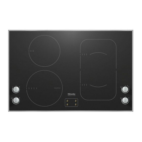
Page 14: Overview
Overview KM 6325-1 a PowerFlex cooking zone with TwinBooster b PowerFlex cooking zone with TwinBooster ab can be combined to form a PowerFlex cooking area c Cooking zone with Booster d Cooking zone with Booster e Display with cooking zone indicators... -
Page 15: Km 6362-1 / Km 6363-1 / Km 6364-1
Overview KM 6362-1 / KM 6363-1 / KM 6364-1 a Cooking zone with WaterBoost b Cooking zone with Booster c PowerFlex cooking zone with TwinBooster d PowerFlex cooking zone with TwinBooster cd can be combined to form a PowerFlex cooking area e Display with cooking zone indicators f Control for the front left cooking zone g Control for the rear left cooking zone... -
Page 16: Control Symbols
Overview Control symbols Symbol Description Cooking zone off Keeping warm setting For switching on the PowerFlex cooking area Booster level 1 B I/II TwinBooster/WaterBoost with 2 levels Cooking zone selection, example: front left Hob display symbols Symbol Description ... -
Page 17: Cooking Zones
Overview Cooking zones Cooking zone KM 6325-1 Rating in watts for 230 V** Ø in cm* 15–23 Normal 2100 TwinBooster, level 1 3000 TwinBooster, level 2 3650 15–23 Normal 2100 TwinBooster, level 1 3000 TwinBooster, level 2 3650 ... - Page 18 Overview Cooking zone KM 6362-1 / 6363-1 / 6364-1 Ø in cm* Rating in watts for 230 V** 10–23 Normal 2300 WaterBoost, level 1 3200 WaterBoost, level 2 5000 14–20 Normal 1850 Booster 3000 15–23 Normal 2100 TwinBooster, level 1 3000 TwinBooster, level 2...
-
Page 19: Before Using For The First Time
Before using for the first time Please stick the extra data plate for Switching on the hob for the the appliance supplied with this doc‐ first time umentation in the space provided in The metal components have a protec‐ the "After sales service, data plate, tive coating which may give off a slight guarantee"... -
Page 20: Induction
Induction The induction principle When the appliance is switched on either deliberately or by mistake, An induction coil is located under each or when there is residual heat cooking zone. When a cooking zone is present, there is the risk of any metal switched on, this coil creates a magnet‐... -
Page 21: Noises
Induction Noises When using an induction cooking zone, the following noises can occur in the pan, depending on what it is made of and how it has been constructed. On the higher power settings, it might buzz. This will decrease or cease alto‐ gether when the power setting is re‐... -
Page 22: Pans
Induction Pans – Often the maximum diameter quoted by manufacturers refers to the diam‐ The following pan types are suitable: eter of the top rim of the pot or pan. The diameter of the base (generally – Stainless steel with a base that can smaller) is more important. -
Page 23: Tips On Saving Energy
Tips on saving energy – Use a lid whenever possible to mini‐ mise heat loss. – Select a smaller pan when cooking small quantities. A smaller pan uses less energy than a larger pan with very little in it. – Cook with as little water as possible. –... -
Page 24: Power Level Range
Power level range Setting range Keeping warm Melting butter Dissolving gelatine Melting chocolate Making milk puddings Warming small quantities of liquid Cooking rice Defrosting frozen vegetables Making porridge Warming liquid and semi-solid foods Making omelettes or lightly frying eggs Steaming fruit Cooking dumplings Steaming vegetables and fish Defrosting and reheating frozen food... -
Page 25: Operation
Operation Residual heat indicator Fire hazard. Do not leave the hob unattended If the cooking zone is still hot, the resid‐ whilst it is being used. ual heat indicator will light up after it Please note that the heating up time has been switched off. -
Page 26: Powerflex Cooking Area
Operation PowerFlex cooking area The PowerFlex cooking zones can be combined to form a PowerFlex cooking area (see "Guide to the appliance - Hob"). Settings for the cooking area are controlled by the front PowerFlex cook‐ ing zone. Switching on ... -
Page 27: Auto Heat-Up
Operation Auto heat-up Continued cook‐ Heat-up time ing setting [min : sec] When Auto heat-up has been activated, the cooking zone switches on automati‐ approx. 0 : 15 cally at the highest power setting and approx. 0 : 15 then switches to the continued cooking setting. -
Page 28: Booster
Operation Booster Cooking zones are networked in pairs to supply the power for the booster The cooking zones are equipped with a function. one stage Booster, two stage Water‐ When the booster function is selected, Boost or TwinBooster (see "Guide to a proportion of energy is taken away the appliance - Hob"). - Page 29 Operation To switch on the Booster Switching off the Booster / Water‐ Boost / TwinBooster Turn the rotary control clockwise gen‐ tly past the point of resistance to B Select a different power level. and back to the point of resistance. The booster symbol will go out.
-
Page 30: Keeping Warm
Operation Keeping warm Setting the keeping warm function Turn the control clockwise to . The keeping warm function is for will appear in the cooking zone dis‐ keeping food that has just been play. cooked warm, i.e. food that is still hot. It is not for reheating food that has gone cold. -
Page 31: Safety Features
Safety features System lock Safety switch-off The safety switch-off mechanism is The system lock is deactivated if triggered automatically if one of the there is an interruption to the power cooking zones is heated for an unusual‐ supply. ly long period of time. This period of time depends on the power level selec‐... -
Page 32: Overheating Protection
– insufficient ventilation of the under‐ side of the hob. – a hot cooking zone being switched on after an interruption to the power supply. If, despite removing the cause, the overheating protection mechanism trig‐ gers again, contact Miele Service. -
Page 33: Cleaning And Care
Cleaning and care Unsuitable cleaning agents Danger of burning. The cooking zones must be switch‐ To avoid damaging the surfaces of your ed off. The hob must have cooled appliance, do not use: down. – washing-up liquid, – cleaning agents containing soda, al‐ ... -
Page 34: Ceramic Surface
Then clean the hob with Miele ceramic and stainless steel hob cleaner (see "Optional accessories") or a suitable proprietary ceramic hob cleaner applied with kitchen paper or a clean cloth. -
Page 35: Problem Solving Guide
Do not open the casing of the appliance. Repairs and other work by unqualified persons could be dangerous and Miele cannot be held liable for unauthorised work. Problem... - Page 36 Problem solving guide Problem Cause and remedy After the hob has been Demonstration mode is activated. switched on appears Turn the rotary control for the front left cooking in the display for a few zone anti-clockwise and hold. seconds.
- Page 37 The cooking zone can now be used again. There is an electronic unit fault. flashes in the dis‐ play alternating Interrupt the power supply to the hob for approx. 1 with numbers. minute. If the problem persists after power is re‐ stored, please contact Miele.
-
Page 38: Optional Accessories
250 ml Miele appliances. These can be ordered online at: Removes heavy soiling, limescale de‐ posits and aluminium residues or from Miele (see end of this booklet Microfibre cloth for contact details). Pans Miele offer a wide range of pans which are perfect for Miele hobs. -
Page 39: Miele@Home / Con@Ctivity
Miele@home and Con@ctivity is availa‐ cooker hoods can ble on the internet and in the instruction manuals of the various components. – be connected to the Miele@home system, – communicate with the cooker hood (Con@ctivity). Miele@home system... -
Page 40: Signing On
Miele@home / Con@ctivity Signing on If you want to sign the hob – on to the Miele@home system, first prepare the signing on procedure on the master (display) appliance. – on to the Con@ctivity system, first sign on the cooker hood. -
Page 41: Safety Instructions For Installation
Safety instructions for installation The appliance must only be installed and connected to the electricity sup‐ ply by a suitably qualified and competent person in strict accordance with cur‐ rent national and local safety regulations. Fit the wall units and cooker hood before fitting the hob to avoid damaging the hob. -
Page 42: Safety Distances
Safety distances Safety distance above the hob A minimum safety distance must be maintained between the appliance and the cooker hood above it. See the cooker hood manufacturer's operating and installation instructions for details. If the manufacturer's instructions are not available for the cooker hood, a minimum safety distance of at least 760 mm must be maintained. - Page 43 Safety distances Safety distances to the sides and back of the hob Ideally the hob should be installed with plenty of space on either side. There may be a wall at the rear or a tall unit or wall on one side (right or left) (see illus‐ trations).
- Page 44 Safety distances Minimum safety distances un‐ Interim shelf derneath the hob It is not necessary to fit an interim shelf underneath the hob but one may be fit‐ To ensure sufficient ventilation to the ted if you wish. hob, a certain gap must be left between the underside of the hob and any oven, Leave a gap of 10 mm at the back of interim shelf or drawer.
- Page 45 Safety distances Safety distance when installing the appliance near a wall with additional niche cladding A minimum safety distance must be maintained between the worktop cut-out and any niche cladding to protect it from heat damage. If the niche cladding is made from a combustible material (e.g. wood) a minimum safety distance ...
-
Page 46: Hob With Frame Or Bevelled Edge
Hob with frame or bevelled edge Installation notes Tiled worktop Seal between the hob and the work‐ Grout lines and the hatched area un‐ derneath the hob frame must be smooth and even. If they are not the hob will not sit flush with the worktop and the sealing strip underneath the Do not use sealant between the hob hob will not provide a good seal be‐... -
Page 47: Building-In Dimensions
Hob with frame or bevelled edge Building-in dimensions KM 6325-1 a Front b Casing depth c Mains connection box d Miele@home/Con@ctivity connection The mains connection cable (1440 mm long) is supplied separately with the hob. -
Page 48: Km 6362-1
Hob with frame or bevelled edge KM 6362-1 a Front b Casing depth c Mains connection box d Miele@home/Con@ctivity connection The mains connection cable (1440 mm long) is supplied separately with the hob. -
Page 49: Km 6363-1
Hob with frame or bevelled edge KM 6363-1 a Front b Casing depth c Mains connection box d Miele@home/Con@ctivity connection The mains connection cable (1440 mm long) is supplied separately with the hob. -
Page 50: Installation
Hob with frame or bevelled edge Installation Installing the hob Feed the mains connection cable Preparing the worktop down through the cut-out. Make the worktop cut-out as shown Place the hob centrally in the cut-out. in the building-in diagram. Observe When doing this, make sure that the the safety distances (see "Safety dis‐... -
Page 51: Flush-Fitted Hobs
Flush-fitted hobs Installation notes The hob can be installed – in a suitable cut-out in a natural Flush fit hobs are only suitable for in‐ stone worktop. stallation in natural stone (granite, marble), tiled or solid wood worktops. – in a suitable cut-out in a tiled or solid Certain models are suitable for build‐... -
Page 52: Building-In Dimensions
KM 6364-1 a Front d Stepped cut-out b Casing depth e Miele@home/Con@ctivity connec‐ tion c Mains connection box The mains connection cable (1440 mm long) is supplied separately with the hob. Please observe the detailed diagrams for cut-out dimensions in natural stone... -
Page 53: Installation
Flush-fitted hobs Installation Solid wood, tiled and glass worktops Natural stone worktops a Worktop a Worktop b Hob b Hob c Gap c Gap d Wooden frame 13 mm (to be provi‐ ded on site) As the ceramic glass and the worktop cut-out have a certain dimensional tol‐... - Page 54 Flush-fitted hobs Preparing the worktop Make the worktop cut-out as shown in "Building-in dimensions". Observe the safety distances (see "Safety dis‐ tances"). Solid wood, tiled and glass worktops: Fix the wooden frame 7 mm below the top edge of the worktop (see dia‐ gram).
-
Page 55: Electrical Connection
Electrical connection Connection Danger of injury. Miele cannot be held liable for unau‐ AC 230 V, 50 Hz thorised installation, maintenance The connection data is quoted on the and repair work as this can be dan‐ dataplate. It must match the household gerous to users. - Page 56 . If the mains cable needs to be replaced it must be replaced with a special con‐ nection cable, type H 05 VV-F (PVC-in‐ sulated), available from Miele. The connection data is quoted on the data plate.
-
Page 57: Wiring Diagram
Electrical connection Wiring diagram a b c d e 200-240 V~ 200-240 V~ 200-240 V~ (L3) 200-240 V~ 200-240 V~ b c d (L2) 200-240 V~... -
Page 58: After Sales Service, Data Plate, Guarantee
– your Miele Dealer, or – Miele See end of this booklet for contact details. When contacting your Dealer or Miele, please quote the model and serial number of your appliance. Data plate Space in which to stick the extra data plate supplied with the appliance. Ensure that the model number is the same as the one on the back page of these instruc‐... - Page 59 Citywest Business Campus, Dublin 24 Dubai Tel: (01) 461 07 10, Fax: (01) 461 07 97 Tel: +971-4-341 84 44 E-Mail: info@miele.ie, Internet: www.miele.ie Fax: +971-4-341 88 52 Manufacturer: Miele & Cie. KG E-Mail: info@miele.ae Internet: www.miele.ae Carl-Miele-Straße 29, 33332 Gütersloh, Germany...
- Page 60 KM 6325-1 / KM 6362-1 / KM 6363-1 / KM 6364-1 en-GB M.-Nr. 10 023 510 / 00...
Need help?
Do you have a question about the KM 6325-1 and is the answer not in the manual?
Questions and answers