Mitsubishi Electric PLFY-P32VBM-E Service Manual
Hide thumbs
Also See for PLFY-P32VBM-E:
- Technical & service manual (45 pages) ,
- Operation manual (38 pages) ,
- Technical & service manual (46 pages)
Table of Contents
Advertisement
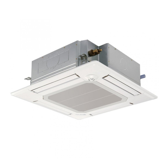
SPLIT-TYPE, HEAT PUMP AIR CONDITIONERS
TECHNICAL & SERVICE MANUAL
Indoor unit
[Model names]
PLFY-P32VBM-E
PLFY-P40VBM-E
PLFY-P50VBM-E
PLFY-P63VBM-E
PLFY-P80VBM-E
PLFY-P100VBM-E
PLFY-P125VBM-E
Model name
indication
INDOOR UNIT
[Service Ref.]
PLFY-P32VBM-E.UK
PLFY-P32VBM-E
1
PLFY-P40VBM-E.UK
PLFY-P40VBM-E
1
PLFY-P50VBM-E.UK
PLFY-P50VBM-E
1
PLFY-P63VBM-E.UK
PLFY-P63VBM-E
1
PLFY-P80VBM-E.UK
PLFY-P80VBM-E
1
PLFY-P100VBM-E.UK
PLFY-P125VBM-E.UK
.UK
.UK
.UK
.UK
.UK
CONTENTS
1. TECHNICAL CHANGES·························2
2. SAFETY PRECAUTION··························2
3. PART NAMES AND FUNCTIONS ··········6
4. SPECIFICATIONS···································8
5. 4-WAY AIR FLOW SYSTEM·················13
6. OUTLINES AND DIMENSIONS············16
7. WIRING DIAGRAM·······························17
8. REFRIGERANT SYSTEM DIAGRAM ·····18
9. TROUBLESHOOTING ··························19
10 . SPECIAL FUNCTION ···························28
11. DISASSEMBLY PROCEDURE ·············31
PARTS CATALOG (OCB413)
October 2007
No. OCH413
REVISED EDITION-A
Revision:
• PLFY-P32/40/50/63/80VBM-E
are added in REVISED EDITION-
A.
• Some descriptions have been
modified.
Please void OCH413.
•
Note:
• This manual does not cover out-
door units.
When servicing them, please
refer to the outdoor unit's service
manual.
• RoHS compliant products have
<G> mark on the spec name
plate.
.UK
1
Advertisement
Table of Contents

Related Manuals for Mitsubishi Electric PLFY-P32VBM-E


Summary of Contents for Mitsubishi Electric PLFY-P32VBM-E
-
Page 1: Table Of Contents
SPLIT-TYPE, HEAT PUMP AIR CONDITIONERS October 2007 No. OCH413 REVISED EDITION-A TECHNICAL & SERVICE MANUAL Indoor unit Revision: [Model names] [Service Ref.] • PLFY-P32/40/50/63/80VBM-E PLFY-P32VBM-E PLFY-P32VBM-E.UK are added in REVISED EDITION- PLFY-P32VBM-E • Some descriptions have been PLFY-P40VBM-E PLFY-P40VBM-E.UK modified. PLFY-P40VBM-E PLFY-P50VBM-E PLFY-P50VBM-E.UK... -
Page 2: Technical Changes
TECHNICAL CHANGES PLFY-P32VBM-E.UK PLFY-P32VBM-E PLFY-P40VBM-E.UK PLFY-P40VBM-E PLFY-P50VBM-E.UK PLFY-P50VBM-E PLFY-P63VBM-E.UK PLFY-P63VBM-E PLFY-P80VBM-E.UK PLFY-P80VBM-E FAN MOTOR(MF) has been changed. TURBO FAN, NUT and WASHER have been changed. SAFETY PRECAUTION CAUTIONS RELATED TO NEW REFRIGERANT Cautions for units utilizing refrigerant R407C Do not use the existing refrigerant piping. - Page 3 [2] Refrigerant recharging (1) Refrigerant recharging process 1Direct charging from the cylinder. ·R407C cylinder available on the market has a syphon pipe. ·Leave the syphon pipe cylinder standing and recharge it. (By liquid refrigerant) Unit Gravimeter (2) Recharge in refrigerant leakage case ·After recovering the all refrigerant in the unit, proceed to working.
- Page 4 Cautions for units utilizing refrigerant R410A Use a vacuum pump with a reverse flow check Do not use the existing refrigerant piping. valve. The old refrigerant and lubricant in the existing piping Vacuum pump oil may flow back into refrigerant cycle and contains a large amount of chlorine which may cause the that can cause deterioration of refrigerant oil etc.
- Page 5 [1] Cautions for service (1) Perform service after recovering the refrigerant left in unit completely. (2) Do not release refrigerant in the air. (3) After completing service, charge the cycle with specified amount of refrigerant. (4) When performing service, install a filter drier simultaneously. Be sure to use a filter drier for new refrigerant.
-
Page 6: Part Names And Functions
PART NAMES AND FUNCTIONS Indoor unit Drain pipe Filter Air outlet Liquid pipe Gas pipe i-see sensor (option) Vane Air intake (Intake grille) -
Page 7: Wired Remote Controller
Wired remote controller “Sensor” indication Display Section Displayed when the remote controller sensor is used. Day-of-Week For purposes of this explanation, Shows the current day of the week. all parts of the display are shown as lit. During actual operation, only Time/Timer Display the relevant items will be lit. -
Page 8: Specifications
SPECIFICATIONS 4-1. SPECIFICATIONS Model PLFY-P32VBM-E PLFY-P40VBM-E PLFY-P50VBM-E PLFY-P63VBM-E Power source 1-phase 220-240V 50Hz, 1-phase 220V 60Hz Cooling capacity kcal / h (Nominal) 3,100 3,900 4,800 6,100 Btu / h 12,300 15,400 19,100 24,200 kcal / h 3,150 4,000 5,000 6,300 Power input 0.03... - Page 9 Model PLFY-P80VBM-E PLFY-P100VBM-E PLFY-P125VBM-E Power source 1-phase 220-240V 50Hz, 1-phase 220V 60Hz 11.2 14.0 Cooling capacity kcal / h 7,700 9,600 12,000 (Nominal) Btu / h 30,700 38,200 47,800 kcal / h 8,000 10,000 12,500 Power input 0.07 0.15 0.16 Current input 0.51 1.00...
- Page 10 4-2. ELECTRICAL PARTS SPECIFICATIONS Service Ref. PLFY-P32VBM-E.UK PLFY-P40VBM-E.UK PLFY-P50VBM-E.UK PLFY-P63VBM-E.UK Symbol PLFY-P32VBM-E PLFY-P40VBM-E PLFY-P50VBM-E PLFY-P63VBM-E Parts name Room temperature TH21 Resistance 0:/15k", 10:/9.6k", 20:/6.3k", 25:/5.4k", 30:/4.3k", 40:/3.0k" thermistor Liquid pipe thermistor TH22 Resistance 0:/15k", 10:/9.6k", 20:/6.3k", 25:/5.4k", 30:/4.3k", 40:/3.0k" Gas pipe thermistor TH23 Resistance 0:/15k", 10:/9.6k", 20:/6.3k", 25:/5.4k", 30:/4.3k", 40:/3.0k"...
-
Page 11: Sound Level
W Note : Refer to WIRING DIAGRAM for the supplied voltage. 4-3. SOUND LEVEL PLFY-P-VBM-E Sound level at anechoic room : Low- Mid2-Mid1 -High Service Ref. Sound level dB (A) PLFY-P32VBM-E 27-28-29-31 PLFY-P50VBM-E 27-28-30-31 PLFY-P40VBM-E PLFY-P63VBM-E 28-29-30-32 PLFY-P80VBM-E 30-32-35-37 PLFY-P100VBM-E.UK... - Page 12 4-4. NC curves PLFY-P32VBM-E PLFY-P40VBM-E PLFY-P50VBM-E External static pressure : 0Pa External static pressure : 0Pa External static pressure : 0Pa Power source : 220,230,240V, 50Hz / 220V, 60Hz Power source : 220,230,240V, 50Hz / 220V, 60Hz Power source : 220,230,240V, 50Hz / 220V, 60Hz...
-
Page 13: Way Air Flow System
4-WAY AIR FLOW SYSTEM 5-1. PLACEMENT OF THE AIR OUTLETS • For this grille, the blowout direction comes in 11 patterns. Also, by setting the remote controller to the appropriate settings, you can adjust the airflow and speed. Select the settings from Table1 according to the location in which you want to install the unit. - Page 14 5-2. Branch duct hole and fresh air intake hole At the time of installation, use the duct holes (cut out) located at the positions shown in following diagram, as and when required. • A fresh air intake hole for the optional multi function casement can also be made. Note: The figures marked with * in the drawing below represent the dimensions of the main unit excluding those of the optional multi function casement.
- Page 15 5-4. FRESH AIR INTAKE AMOUNT & STATIC PRESSURE CHARACTERISTICS l l PLFY-P32 · P40 · P50 · P63 · P80VBM-E Multifunction casement + Standard filter Multifunction casement + High efficiency filter 2 - inlet 2 - inlet -100 -100 -150 -150 1 - inlet 1 - inlet...
-
Page 16: Outlines And Dimensions
OUTLINES AND DIMENSIONS PLFY-P32VBM-E.UK PLFY-P40VBM-E.UK PLFY-P50VBM-E.UK PLFY-P63VBM-E.UK PLFY-P80VBM-E.UK PLFY-P100VBM-E.UK PLFY-P125VBM-E.UK PLFY-P32VBM-E .UK PLFY-P40VBM-E .UK PLFY-P50VBM-E PLFY-P63VBM-E PLFY-P80VBM-E Unit : mm Ceiling hole 20~45 860~910 20~45 Detail connecting of branch duct(Both aspects) Fresh air Suspension bolt pitch Cut out hole intake hole... -
Page 17: Wiring Diagram
WIRING DIAGRAM PLFY-P32VBM-E.UK PLFY-P40VBM-E.UK PLFY-P50VBM-E.UK PLFY-P63VBM-E.UK PLFY-P80VBM-E.UK PLFY-P100VBM-E.UK PLFY-P125VBM-E.UK PLFY-P32VBM-E .UK PLFY-P40VBM-E .UK PLFY-P50VBM-E PLFY-P63VBM-E PLFY-P80VBM-E [LEGEND] SYMBOL NAME SYMBOL NAME SYMBOL NAME I. B INDOOR CONTROLLER BOARD TERMINAL POWER SUPPLY OPTION PART CN27 BLOCK TRANSMISSION CONNECTOR DAMPER PCB FOR WIRELESS REMOTE CONTROLLER... -
Page 18: Refrigerant System Diagram
REFRIGERANT SYSTEM DIAGRAM PLFY-P32VBM-E.UK PLFY-P40VBM-E.UK PLFY-P50VBM-E.UK PLFY-P63VBM-E.UK PLFY-P80VBM-E.UK PLFY-P100VBM-E.UK PLFY-P125VBM-E.UK PLFY-P32VBM-E .UK PLFY-P40VBM-E .UK PLFY-P50VBM-E PLFY-P63VBM-E PLFY-P80VBM-E Strainer (#100mesh) Gas pipe thermistor TH23 Gas pipe Liquid pipe thermistor TH22 Flare connection Liquid pipe Heat exchanger Linear expansion valve Strainer1 (#50mesh) -
Page 19: Troubleshooting
TROUBLESHOOTING 9-1. HOW TO CHECK THE PARTS PLFY-P32/40/50/63/80/100/125VBM-E.UK PLFY-P32/40/50/63/80VBM-E Parts name Check points Room temperature Disconnect the connector then measure the resistance with a tester. thermistor (TH21) (At the ambient temperature of 10:~30:) Liquid pipe thermistor (TH22) Normal Abnormal (Refer to Thermistor characteristic graph.) Gas pipe thermistor 4.3k"~9.6k"... -
Page 20: Linear Expansion Valve
9-1-1. Thermistor <Thermistor characteristic graph> < Thermistor for lower temperature > Thermistor for Room temperature thermistor(TH21) lower temperature Liquid pipe temperature thermistor(TH22) Gas pipe temperature thermistor(TH23) Thermistor R =15k' ± 3% Fixed number of B=3480K ± 2% Rt=15exp { 3480( 273+t 15k' 9.6k'... - Page 21 <Output pulse signal and the valve operation> Output Output (Phase) Closing a valve : 1 Opening a valve : 4 The output pulse shifts in above order. • When linear expansion valve operation stops, all output phase become OFF. • At phase interruption or when phase does not shift in order, motor does not rotate smoothly and motor will lock and vibrate.
- Page 22 9-1-3. DC Fan motor (fan motor / indoor controller board) Check method of indoor fan motor (fan motor / indoor controller board) Notes · High voltage is applied to the connecter (CNMF) for the fan motor. Give attention to the service. ·...
-
Page 23: Function Of Dip Switch
9-2. FUNCTION OF DIP SWITCH Operation by switch Effective Switch Pole Function Remarks timing Thermistor <Room temperature Address board Built-in remote controller Indoor unit detection> position <Initial setting> Filter clogging detection Provided Not provided Filter cleaning 2,500hr 100hr 1 2 3 4 5 6 7 8 9 10 Note : Fresh air intake Effective... - Page 24 Effective Switch Pole Operation by switch Remarks timing Address board Ceiling height can be changed depends on SWB setting. (High ceiling) <Initial setting> Ceiling (Standard) height PLFY-P32·P40·P50·P63·P80VBM-E (Silent) selector Silent Standard High ceiling 4 direction 2.5m 2.7m 3.5m 3 direction 2.7m 3.0m 3.5m...
- Page 25 Effective Switch Pole Operation by switch Remarks timing • To operate each indoor unit by each remote controller when installed 2 indoor <Initial setting> units or more are near, Pair No. setting is necessary. Pattern A 1 Pair No. setting is available with the 4 patterns (Setting patters A to D). 2 Make setting for J41, J42 of indoor controller board and the Pair No.
- Page 26 9-3. TEST POINT DIAGRAM 9-3-1. Indoor controller board PLFY-P32/40/50/63/80/100/125VBM-E.UK PLFY-P32/40/50/63/80VBM-E CN6Y CN60 i-See sensor motor output Linear expansion valve (LEV) 12VDC pulse output output 12VDC pulse output CN3A CN4Y Connect to the terminal block (TB15) i-See sensor (MA-Remote controller connecting wire) 1 1 - 3 3 : 8.7-13V DC (Pin1 1 (+)) CN52 Remote indicator...
- Page 27 9-3-2. Address board PLFY-P32VBM-E.UK PLFY-P40VBM-E.UK PLFY-P50VBM-E.UK PLFY-P63VBM-E.UK PLFY-P80VBM-E.UK PLFY-P100VBM-E.UK PLFY-P125VBM-E.UK PLFY-P32VBM-E PLFY-P40VBM-E PLFY-P50VBM-E PLFY-P63VBM-E PLFY-P80VBM-E Discharge outlet Function setting Ceiling hight selector number selector SW12 SW11 Address setting Address setting Option selector 2nd digit 1st digit...
-
Page 28: Special Function
SPECIAL FUNCTION 10-1. HOW TO PERFORM THE UP/DOWN OPERATION OF THE AIR INTAKE GRILLE 10-1.1.Setting up the lowering distance of air intake grille Unit You can set up 8 different stages of lowering distance for Decorative the air intake grille according to the set up location if desired. panel * As a factory default, the decorative panel will automatically stop at 1.6 m from the ceiling surface. - Page 29 10-1-3. How to perform the up/down operation using wired remote controller (PAR-21MAA) General Operation * Raise or lower all the air intake grilles managed by the remote controller at the same time. Install the remote controller in a place where you can observe all the air-conditioners. Otherwise, the lowering grille may make contact with something and cause damage to it.
- Page 30 Up/down operation with the individual specified air-conditioner (When used in combination with CITY MULTI model) * Raise or lower the air intake grille of the specific air-conditioner that you select from all that are managed by that remote controller. 1) Ensure that the air-conditioner is not running. Ensure that the air-conditioner is not running.
-
Page 31: Disassembly Procedure
DISASSEMBLY PROCEDURE PLFY-P32VBM-E.UK PLFY-P40VBM-E.UK PLFY-P50VBM-E.UK PLFY-P63VBM-E.UK PLFY-P80VBM-E.UK PLFY-P100VBM-E.UK PLFY-P125VBM-E.UK PLFY-P32VBM-E .UK PLFY-P40VBM-E .UK PLFY-P50VBM-E PLFY-P63VBM-E PLFY-P80VBM-E Be careful on removing heavy parts. OPERATING PROCEDURE PHOTOS & ILLUSTRATIONS 1. Removing the air intake grille Figure 1 Filter (1) Slide the knob of air intake grille toward the arrow 1 to open the air intake grille. - Page 32 OPERATING PROCEDURE PHOTOS & ILLUSTRATIONS Coil plate Photo 3 6. Removing the fan and fan motor (MF) (1) Remove the electrical box. (See photo 2) (2) Remove the bell mouth (3 screws). (See photo 2) (3) Remove the turbo fan nut. (4) Pull out the turbo fan.
- Page 33 OPERATING PROCEDURE PHOTOS & ILLUSTRATIONS Photo 8 10 Removing the drain pump (DP) and float switch (FS) (1) Remove the drain pan. (See photo 6) Float switch (2) Cut the hose band and remove the hose. (3) Remove the drain pump assembly (3 screws and 2 hooks). Hose band (4) Remove the drain pump (3 screws).
- Page 36 HEAD OFFICE : TOKYO BLDG., 2-7-3, MARUNOUCHI, CHIYODA-KU TOKYO 100-8310, JAPAN cCopyright 2007 MITSUBISHI ELECTRIC ENGINEERING CO., LTD. New publication, effective Oct. 2007 Distributed in Oct. 2007 No. OCH413 REVISED EDITION-A PDF 7 Distributed in Mar. 2007 No. OCH413 PDF 7...
Need help?
Do you have a question about the PLFY-P32VBM-E and is the answer not in the manual?
Questions and answers