Table of Contents
Advertisement
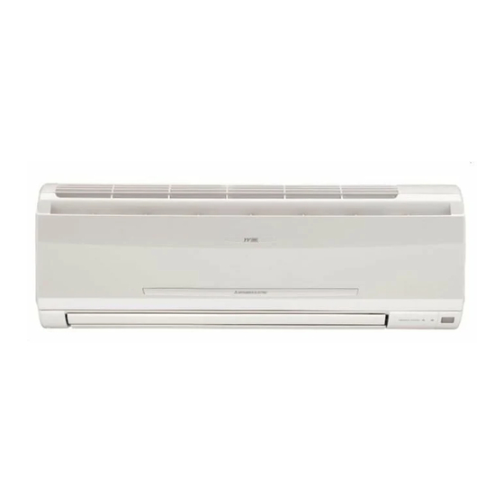
SPLIT-TYPE, AIR CONDITIONERS
SPLIT-TYPE, HEAT PUMP AIR CONDITIONERS
INDOOR UNIT
SERVICE MANUAL
Wireless type
Models
MSC-GA20VB -
MSC-GA25VB -
MSC-GA35VB -
NOTE:
This service manual describes technical data of the indoor units.
RoHS compliant products have <G> mark on the spec name plate.
For servicing of RoHS compliant products, refer to the RoHS PARTS LIST (RoHS compliant).
E1
E1
E1
CONTENTS
1. TECHNICAL CHANGES ····································3
2. PART NAMES AND FUNCTIONS······················3
3. SPECIFICATION·················································5
4. NOISE CRITERIA CURVES ·······························5
5. OUTLINES AND DIMENSIONS ·························6
6. WIRING DIAGRAM ············································7
7. REFRIGERANT SYSTEM DIAGRAM ················8
8. SERVICE FUNCTIONS ······································8
9. TROUBLESHOOTING······································11
10. DISASSEMBLY INSTRUCTIONS·····················18
11. PARTS LIST······················································20
12. RoHS PARTS LIST···········································22
13. OPTIONAL PARTS ·························BACK PAGE
RoHS PARTS LIST has been added.
Please void OB385.
No. OB385
REVISED EDITION-A
Outdoor unit service manual
MU-GA•VB Series (OB386)
MUH-GA•VB Series (OB387)
MUX-A•VB Series (OB384)
MXZ-A•WV Series (OB319)
Advertisement
Table of Contents
Troubleshooting

Related Manuals for Mitsubishi Electric MSC-GA20VB- E1


Summary of Contents for Mitsubishi Electric MSC-GA20VB- E1
-
Page 1: Table Of Contents
Revision A: RoHS PARTS LIST has been added. SPLIT-TYPE, AIR CONDITIONERS Please void OB385. SPLIT-TYPE, HEAT PUMP AIR CONDITIONERS INDOOR UNIT No. OB385 SERVICE MANUAL REVISED EDITION-A Wireless type Models MSC-GA20VB - MSC-GA25VB - MSC-GA35VB - Outdoor unit service manual MU-GA•VB Series (OB386) MUH-GA•VB Series (OB387) MUX-A•VB Series (OB384) -
Page 2: Revision A
Revision A : • RoHS PARTS LIST has been added. -
Page 3: Technical Changes
TECHNICAL CHANGES MSC-A07YV - MSC-GA20VB - 1. Indication of capacity has been changed. (BTU base 2. P.C. board has been changed. 3. Air cleaning filter has been changed to optional parts. 4. Fan motor has been changed. 5. Fan motor capacitor has been changed. 6. -
Page 4: Remote Controller
MSC-GA20VB MSC-GA25VB MSC-GA35VB ACCESSORIES Installation plate Installation plate fixing screw 4 o 25 mm Remote controller holder Fixing screw for 3 3.5 o 16 mm Battery (AAA) for remote controller Wireless remote controller Felt tape (Used for left or left-rear piping) REMOTE CONTROLLER Signal transmitting section Operation display section... -
Page 5: Specification
SPECIFICATION Indoor model MSC-GA20VB MSC-GA25VB MSC-GA35VB Cooling Heating Cooling Heating Cooling Heating Function Single phase Single phase Single phase Indoor unit power supply 230V,50Hz 230V,50Hz 230V,50Hz K /h Capacity Air flow(High/Med. /Low ) 474/372 /276 510/420 /342 474/384 /306 588/456 /342 582/444 /324 606/498 /396 Power outlet... -
Page 6: Outlines And Dimensions
MSC-GA35VB SPL(dB LINE FAN SPEED FUNCTION COOLING High HEATING Test conditions. Cooling : DB27: WB19: Heating : DB20: WB -: NC-70 NC-60 NC-50 INDOORUNIT WALL NC-40 NC-30 0.8m APPROXIMATE TERESHOLD OF HEARING FOR NC-20 MICROPHONE CONTINUOUS NOISE 1000 2000 4000 8000 BAND CENTER FREQUENCIES, Hz OUTLINES AND DIMENSIONS... -
Page 7: Wiring Diagram
MSC-GA35VB 161.5 161.5 Installation plate Indoor unit 81.5 81.5 Wall hole Air in Installation plate Liquid line 6.35-0.5m Gas line 9.52-0.43m Insulation 37 O.D 21 I.D Drain hose (Connected part O,D) Insulation Air out Power supply cord Lead to right 1.0m Lead to left 0.3m Wireless remote controller WIRING DIAGRAM... -
Page 8: Refrigerant System Diagram
REFRIGERANT SYSTEM DIAGRAM MSC-GA20VB MSC-GA25VB MSC-GA35VB Refrigerant pipe [9.52 Unit:mm (with heat insulator) Indoor coil Indoor thermistor heat RT12 exchanger Flared connection Room temperature thermistor RT11 Flared connection Refrigerant flow Refrigerant pipe [6.35 in cooling (with heat insulator) SERVICE FUNCTIONS MSC-GA20VB MSC-GA25VB MSC-GA35VB... - Page 9 Remote controller model : KM04F The P.C. board has the print “J1” and “J2”. Solder “J1” and “J2” according to the number of indoor unit as shown in Table 1. After modification, press the RESET button. Table 1 1 unit operation 2 units operation 3 units operation 4 units operation...
- Page 10 8-4. MU & MUX TYPE / MUH & MXZ TYPE SWITCH OVER AND AUTO RESTART FUNCTION 1. MU & MUX TYPE / MUH & MXZ TYPE SWITCH OVER SW2-1 sets the AUTO RESTART FUNCTION ON / OFF. SW2-2 switches over the MU & MUX type / MUH & MXZ type. The indoor units for MU &...
-
Page 11: Troubleshooting
TROUBLESHOOTING MSC-GA20VB MSC-GA25VB MSC-GA35VB 9-1. Cautions on troubleshooting 1. Before troubleshooting, check the following: 1) Check the power supply voltage. 2) Check the indoor/outdoor connecting wire for mis-wiring. 2. Take care the following during servicing. 1) Before servicing the air conditioner, be sure to turn OFF the main unit first with the remote controller, and then after confirming the horizontal vane is closed, turn OFF the breaker and/or disconnect the power plug. - Page 12 9-2. Instruction of troubleshooting MSC-GA20VB MSC-GA25VB MSC-GA35VB Start Indoor unit OPERATION Indoor unit Indoor unit Indoor unit operates. INDICATOR operates. operates. doesn't receive Outdoor unit lamp on the But indoor Outdoor unit the signal from doesn't operate indoor unit is unit doesn't doesn't remote controller.
-
Page 13: Troubleshooting Check Table
9-3. Troubleshooting check table • The following indication does not depend on the shape of lamp. flashing Operation Indicator · Flashing of the OPERATION INDICATOR lamp (on the left-hand side) indicates possible abnormalities. · The OPERATION INDICATOR lamp (on the left-hand side) is lighting during normal operation. Before taking measures, make sure that the symptom reappears, for accurate troubleshooting. - Page 14 9-4. Trouble criterion of main parts MSC-GA20VB MSC-GA25VB MSC-GA35VB Part name Check method and criterion Figure Room Measure the resistance with a tester. temperature (Part temperature 10°C ~ 30°C) thermistor (RT11) Normal Abnormal MSC-GA20/GA25/GA35VB Indoor coil Open or thermistor (RT12) short-circuit 8kΩ...
- Page 15 Indoor unit operates by pressing the EMERGENCY OPERATION switch, but doesn’t operate with the remote controller. B B Check of remote controller and receiver P.C. board wCheck the remote controller is exclusive for this air conditioner. Switch on the remote controller. Is LCD display on the remote con- Replace the batteries.
- Page 16 When OPERATION INDICATOR lamp flashes 0.5-second intervals or 1-time. Outdoor unit does not operate. <MUH-GA20/GA25/GA35VB, MXZ-A14/A18/A26/A32WV> D D How to check mis-wiring and serial signal error 1 Set the switch(SW2-2) on indoor electronic control P.C. board to MU or MUX type, when the outdoor unit is MU or MUX type. If the setting is MUH or MXZ type, the unit does not work.
- Page 17 9-6. Test point diagram and voltage MSC-GA20VB MSC-GA25VB MSC-GA35VB Indoor electronic control P.C. board Power supply input 230V AC Fuse F11 250V AC 3.15A R132 Indoor fan motor 230V AC Safety device of fan by horizontal vane CN1R1 Room temperature Varistor thermistor RT11 (NR11)
-
Page 18: Disassembly Instructions
DISASSEMBLY INSTRUCTIONS <"Terminal with locking mechanism" Detaching points> The terminal which has the locking mechanism can be detached as shown below. There are two types ( Refer to (1) and (2)) of the terminal with locking mechanism. The terminal without locking mechanism can be detached by pulling it out. Check the shape of the terminal before detaching. - Page 19 OPERATING PROCEDURE PHOTOS Vane motor 3. Removing the electrical box Indoor coil thermistor Photo 3 connector (1) Remove the front panel. (Refer to 1.) connector (2) Remove the electrical cover. (Refer to 2.) Screw of the (3) Remove the V.A. clamp. (Refer to 2.) electrical box (4) Remove the cord clamp.
-
Page 20: Parts List
PARTS LIST (non-RoHS compliant) MSC-GA20VB MSC-GA25VB MSC-GA35VB 11-2. ACCESSORY AND 11-1. INDOOR UNIT STRUCTURAL PARTS REMOTE CONTROLLER 1 (W) 8 (W) Optional parts (See 13.) (W) These figures show about MSC-GA35VB. 6 (W) 11-1. INDOOR UNIT STRUCTURAL PARTS Symbol Q'ty/unit in Wiring Part No. - Page 21 PARTS LIST (non-RoHS compliant) MSC-GA20VB MSC-GA25VB MSC-GA35VB 11-4. INDOOR UNIT HEAT EXCHANGER 11-3. INDOOR UNIT ELECTRICAL PARTS AND FUNCTIONAL PARTS 20 (W) (W) This figure shows MSC-GA35VB. 11-3. INDOOR UNIT ELECTRICAL PARTS AND FUNCTIONAL PARTS Part number that is circled is not shown in the illustration. Q'ty/unit Symbol in Wiring...
-
Page 22: Rohs Parts List
ROHS PARTS LIST (RoHS compliant) MSC-GA20VB MSC-GA25VB MSC-GA35VB 12-2. ACCESSORY AND 12-1. INDOOR UNIT STRUCTURAL PARTS REMOTE CONTROLLER 1 (W) 8 (W) Optional parts (See 13.) (W) These figures show about MSC-GA35VB. 6 (W) 12-1. INDOOR UNIT STRUCTURAL PARTS Symbol Q'ty/unit in Wiring Part No. - Page 23 ROHS PARTS LIST (RoHS compliant) MSC-GA20VB MSC-GA25VB MSC-GA35VB 12-4. INDOOR UNIT HEAT EXCHANGER 12-3. INDOOR UNIT ELECTRICAL PARTS AND FUNCTIONAL PARTS 20 (W) (W) This figure shows MSC-GA35VB. 12-3. INDOOR UNIT ELECTRICAL PARTS AND FUNCTIONAL PARTS Part number that is circled is not shown in the illustration. Q'ty/unit Symbol in Wiring...
-
Page 24: Optional Parts
Air cleaning filter (White bellows type) HEAD OFFICE: TOKYO BLDG., 2-7-3, MARUNOUCHI, CHIYODA-KU, TOKYO 100-8310, JAPAN C C Copyright 2005 MITSUBISHI ELECTRIC ENGINEERING CO.,LTD Distributed in May 2006. No.OB385 REVISED EDITION-A 6 New publication, effective May 2006 Distributed in Jan. 2005. No.OB385 6 Specifications subject to change without notice.
Need help?
Do you have a question about the MSC-GA20VB- E1 and is the answer not in the manual?
Questions and answers