Table of Contents
Advertisement
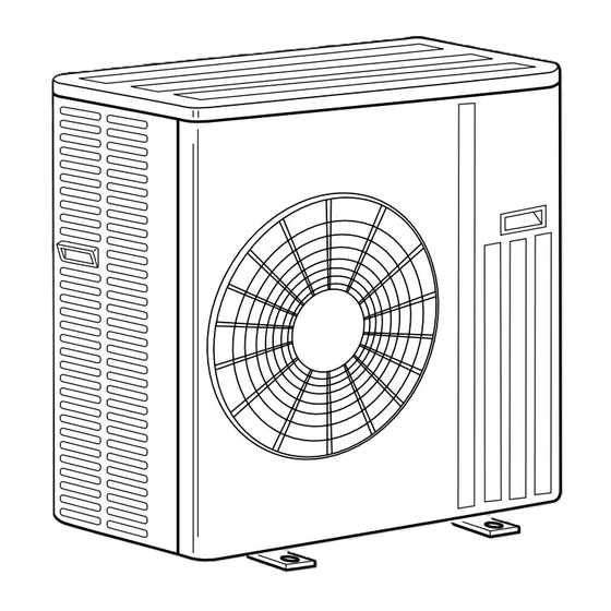
OUTDOOR UNIT
SERVICE MANUAL
Models
MUZ-GB50VA -
MUZ-GB50VA -
MUZ-GB50VA -
NOTE:
• This service manual describes technical data of the outdoor units.
• Errors in TROUBLESHOOTING have been
corrected.
Please void OB455 REVISED EDITION-F.
HFC
utilized
R410A
E1
E2
E3
CONTENTS
1. TECHNICAL CHANGES ··································· 3
2. PART NAMES AND FUNCTIONS ····················· 4
3. SPECIFICATION ················································ 4
4. NOISE CRITERIA CURVES ······························ 6
5. OUTLINES AND DIMENSIONS ························ 6
6. WIRING DIAGRAM ············································ 7
7. REFRIGERANT SYSTEM DIAGRAM ··············· 9
8. PERFORMANCE CURVES ····························· 11
9. ACTUATOR CONTROL ··································· 16
10. SERVICE FUNCTIONS ···································· 17
11. TROUBLESHOOTING ····································· 18
12. DISASSEMBLY INSTRUCTIONS ···················· 44
13. RoHS PARTS LIST ·········································· 48
No. OB455
REVISED EDITION-G
Indoor unit service manual
MSZ-GB·VA Series (OB454)
Advertisement
Table of Contents
Troubleshooting

Related Manuals for Mitsubishi Electric MUZ-GB50VA


Summary of Contents for Mitsubishi Electric MUZ-GB50VA
-
Page 1: Table Of Contents
Please void OB455 REVISED EDITION-F. OUTDOOR UNIT No. OB455 SERVICE MANUAL REVISED EDITION-G utilized R410A Models MUZ-GB50VA - MUZ-GB50VA - MUZ-GB50VA - Indoor unit service manual MSZ-GB·VA Series (OB454) CONTENTS 1. TECHNICAL CHANGES ··································· 3 2. PART NAMES AND FUNCTIONS ····················· 4 3. -
Page 2: Revision G
• RoHS PARTS LIST has been changed. Revision D: • RoHS PARTS LIST has been changed. Revision E: • MUZ-GB50VA- has been added. Revision F: • The fan guard for MUZ-GB50VA- has been changed. Revision G: • Errors in TROUBLESHOOTING have been corrected. -
Page 3: Technical Changes
TECHNICAL CHANGES MUZ-GA50VA - MUZ-GB50VA - 1. Refrigerant filling capacity has been changed. 2. Outdoor electronic control P.C. board has been changed. MUZ-GB50VA - MUZ-GB50VA - 1. Compressor has been changed. (SNB130FLDH1 SNB130FLEH1) 2. Outdoor electronic control P.C. board has been changed. -
Page 4: Part Names And Functions
PART NAMES AND FUNCTIONS MUZ-GB50VA ACCESSORIES Air inlet (back and side) Piping Drain socket Drain cap ø33 Drain hose Air outlet Drain outlet SPECIFICATION Outdoor model MUZ-GB50VA Function Cooling Heating Power supply Single phase 230 V, 50 Hz Capacity Rated frequency (Min.-Max.) 5.0 (0.9-5.8) - Page 5 Specifi cations and rated conditions of main electric parts Model MUZ-GB50VA- MUZ-GB50VA- Item (CT1,2) 20 A Current transformer (CT61) 20 A Smoothing capacitor (CB1,2,3) 560 μF 450 V (F64) 250 V 2 A Fuse (F801) 250 V 3.15 A (F911)
-
Page 6: Noise Criteria Curves
NOISE CRITERIA CURVES MUZ-GB50VA FAN SPEED FUNCTION SPL(dB(A)) LINE COOLING NC-70 High HEATING NC-60 Test conditions Cooling : Dry-bulb temperature 35°C NC-50 Wet-bulb temperature (24°C) Heating : Dry-bulb temperature 7°C Wet-bulb temperature 6°C NC-40 OUTDOOR UNIT NC-30 MICROPHONE APPROXIMATE THRESHOLD OF... -
Page 7: Wiring Diagram
WIRING DIAGRAM MUZ-GB50VA- MUZ-GB50VA-... - Page 8 MUZ-GB50VA-...
-
Page 9: Refrigerant System Diagram
REFRIGERANT SYSTEM DIAGRAM MUZ-GB50VA- Unit: mm Muffler #100 4-way valve Refrigerant pipe ø12.7 (with heat insulator) Stop valve (with service port) Outdoor Flared connection Discharge heat Ambient temperature exchanger temperature thermistor Defrost thermistor RT62 thermistor RT65 RT61 Compressor Outdoor heat... - Page 10 MUZ-GB50VA- Unit: mm Muffler #100 4-way valve Refrigerant pipe ø12.7 (with heat insulator) Stop valve (with service port) Outdoor Flared connection Discharge heat Ambient temperature exchanger temperature thermistor Defrost thermistor RT62 thermistor RT65 RT61 Compressor Outdoor heat exchanger temperature thermistor...
-
Page 11: Performance Curves
PERFORMANCE CURVES MUZ-GB50VA The standard specifications apply only to the operation of the air conditioner under normal conditions. Since operating condi- tions vary according to the areas where these units are installed, the following information has been provided to clarify the operating characteristics of the air conditioner under the conditions indicated by the performance curve. - Page 12 Total input (Cooling) 11.8 10.7 Indoor intake air Wet-bulb temperature(°C) Outdoor intake air Dry-bulb temperature (°C) Heating capacity Total input(Heating) 33.6 31.0 28.4 25.8 23.3 20.7 18.1 15.5 12.9 10.3 Outdoor intake air Wet-bulb temperature ( °C ) Outdoor intake air Wet-bulb temperature ( °C ) NOTE : The above broken lines are for the heating operation without any frost and defrost operation.
-
Page 13: Cool Operation
8-4. OUTDOOR LOW PRESSURE AND OUTDOOR UNIT CURRENT COOL operation Dry-bulb temperature (°C) Relative humidity (%) Both indoor and outdoor unit are under the same temperature/ humidity condition. Operation : TEST RUN OPERATION (Refer to 8-3.) MUZ-GB50VA (kgf/ [Gauge]) (MPa [Gauge]) 35(°C) 35(°C) Ambient temperature(°C) Ambient temperature(°C) - Page 14 PERFORMANCE DATA COOL operation at Rated frequency MSZ-GB50VA : MUZ-GB50VA CAPACITY : 5.0 kW SHF : 0.69 INPUT : 1650 W OUTDOOR DB (°C) INDOOR INDOOR DB (°C) WB (°C) INPUT INPUT INPUT INPUT 5.88 3.00 0.51 1320 5.63 2.87 0.51...
- Page 15 PERFORMANCE DATA COOL operation at Rated frequency MSZ-GB50VA : MUZ-GB50VA CAPACITY : 5.0 kW SHF : 0.69 INPUT : 1650 W OUTDOOR DB (°C) INDOOR INDOOR DB (°C) WB (°C) INPUT INPUT INPUT 4.90 2.50 0.51 1617 4.50 2.30 0.51 1716 4.30...
-
Page 16: Actuator Control
PERFORMANCE DATA HEAT operation at Rated frequency MSZ-GB50VA : MUZ-GB50VA CAPACITY : 5.8 kW INPUT : 1700 W OUTDOOR WB (°C) INDOOR DB (°C) INPUT INPUT INPUT INPUT INPUT INPUT INPUT 3.65 1105 4.41 1326 5.16 1496 5.92 1615 6.67 1717 7.37... -
Page 17: Service Functions
9-3. RELATION BETWEEN MAIN SENSOR AND ACTUATOR MUZ-GB50VA Actuator Sensor Purpose Outdoor fan Indoor fan Compressor R.V. coil motor motor ○ ○ Discharge temperature thermistor Protection ○ Cooling : Coil frost prevention ○ ○ Indoor coil temperature thermistor Heating : High pressure protection ○... -
Page 18: Troubleshooting
TROUBLESHOOTING MUZ-GB50VA 11-1. CAUTIONS ON TROUBLESHOOTING 1. Before troubleshooting, check the following 1) Check the power supply voltage. 2) Check the indoor/outdoor connecting wire for miswiring. 2. Take care of the following during servicing 1) Before servicing the air conditioner, be sure to turn OFF the main unit first with the remote controller, and after con- firming the horizontal vane is closed, turn off the breaker and/or disconnect the power plug. -
Page 19: Failure Mode Recall Function
11-2. FAILURE MODE RECALL FUNCTION Outline of the function This air conditioner can memorize the abnormal condition which has occurred once. Even though LED indication listed on the troubleshooting check table (11-3.) disappears, the memorized failure details can be recalled. This mode is very useful when the unit needs to be repaired for the abnormality which does not recur. - Page 20 2. Flow chart of the detailed outdoor unit failure mode recall function Operational procedure The outdoor unit might be abnormal. Confi rm if outdoor unit is abnormal according to the following procedures. Confi rm that the remote controller is in the failure mode recall function. 1.
- Page 21 3. Outdoor unit failure mode table MUZ-GB50VA- LED indication Indoor/ (Outdoor P.C. The left lamp of Abnormal point outdoor unit board) OPERATION INDICATOR Condition Remedy (Failure mode / protection) failure mode lamp (Indoor unit) recall function LED1 LED2 None (Normal) —...
- Page 22 MUZ-GB50VA- Indoor/outdoor The left lamp of Outdoor unit Abnormal point LED indication unit failure OPERATION INDICATOR Condition Remedy failure mode (Failure mode / protection) (Outdoor P.C. board) mode recall lamp (Indoor unit) recall function function None (Normal) — — —...
-
Page 23: Troubleshooting Check Table
11-3. TROUBLESHOOTING CHECK TABLE MUZ-GB50VA- LED indication Abnormal point/ Con- Symptom Condition Remedy dition LED1(Red) LED2(Yellow) Outdoor unit Outdoor power system Overcurrent protection stop is continuously performed 3 times • Check the connection of the com- does not oper- within 1 minute after the compressor gets started, or when pressor connecting wire. - Page 24 LED indication Abnormal point/ Con- Symptom Condition Remedy dition LED1(Red) LED2(Yellow) Primary current pro- The input current exceeds 15 A. These symptoms do not mean any Outdoor unit tection abnormality of the product, but operates. Once Lighting check the following points. Secondary current pro- The current of the compressor exceeds 15 A.
- Page 25 MUZ-GB50VA- Abnormal point/ Con- Symptom LED indication Condition Remedy dition Outdoor unit 1-time fl ash every Outdoor power sys- Overcurrent protection stop is continuously performed 3 times • Reconnect connector of compres- does not oper- 2.5 seconds within 1 minute after the compressor gets started, or failure of sor.
- Page 26 11-4. TROUBLE CRITERION OF MAIN PARTS MUZ-GB50VA Part name Check method and criterion Figure Defrost thermistor (RT61) Ambient temperature Measure the resistance with a tester. thermistor (RT65) Refer to 11-6. "Test point diagram and voltage", 1. "Outdoor electronic con- Outdoor heat exchanger tem- trol P.C.
-
Page 27: A How To Check Inverter/Compressor
11-5. TROUBLESHOOTING FLOW A How to check inverter/compressor MUZ-GB50VA- Disconnect the terminal of the compressor. 3 minutes after turn- ing on the power supply, start EMERGENCY OPERATION. • After the outdoor fan starts running, wait for 1 minute or more before measuring the voltage. - Page 28 B Check of open phase MUZ-GB50VA- ● With the connector between the compressor and the intelligent power module disconnected, activate the inverter and check if the inverter is normal by measuring the balance of voltage between the terminals. Output voltage is 50 - 130 V. (The voltage may differ according to the tester.) <<...
- Page 29 <<Judgement>> E Check of compressor operation time 0 second Compressor starts MUZ-GB50VA- 1 second Abnormal (IPM failure) ●Connect the compressor and activate the inverter. Then measure (Compressor winding short) 2 seconds the time until the inverter stops due to over current.
- Page 30 Turn ON the power supply and press EMERGENCY OPERATION switch. Does the unit operate for 10 minutes or more Replace the inverter P.C. board without showing thermistor abnormality? or the outdoor power board. (Cause is poor contact.) MUZ-GB50VA- Thermistor Symbol Connector, Pin No. Board Defrost...
- Page 31 H Check of R.V. coil MUZ-GB50VA- • Heating operation does not work. Disconnect the lead wire leading to the compressor. 3 minutes after turning on the power supply, start EMERGENCY OPERATION in HEAT mode. Is there voltage of 230 VAC between pin1 and...
- Page 32 MUZ-GB50VA- First of all, measure the resistance of R.V. coil to check if the coil is defective. Refer to 11-4. In case CN721 is not connected or R.V. coil is open, voltage is generated between the terminal pins of the connector although any signal is not being transmitted to R.V.
- Page 33 I Check of outdoor fan motor Check the connection between the connector CN931 and CN932. Is the resistance between each ter- minal of outdoor fan motor normal? (Refer to 11-4.) Disconnect CN932 from outdoor electronic control P.C. board or the inverter P.C. board, and turn on the power supply. Rotate the outdoor fan motor manually and measure the voltage of CN931.
- Page 34 J Check of power supply MUZ-GB50VA- Check the connecting of parts of main power supply circuit. Turn ON power supply. Is there voltage of 230 VAC in the power sup- Check the power supply cable. ply terminal block? Is the output voltage from the noise fi lter P.C.
- Page 35 K Check of LEV MUZ-GB50VA- Turn ON power supply to the outdoor unit after checking LEV coil is mounted to the LEV body securely. Is "click - click" sound heard? Normal Or, do you feel vibration of the LEV coil with a hand? Disconnect the connector CN795.
- Page 36 L Check of inverter P.C. board MUZ-GB50VA- Check the outdoor fan motor. (Refer to 11-5. .) Is the fuse (F901) blown on the in- verter P.C. board? Check the connection of the connectors (CN931, CN932) of the outdoor fan mo- tor.
- Page 37 M How to check miswiring and serial signal error Turn OFF the power supply. Is there rated voltage in the Check the power supply. power supply? Turn ON the power supply. Is there rated voltage between outdoor termi- Check the wiring. nal block S1 and S2? Press EMERGENCY OPERATION switch once.
- Page 38 N Check of bus-bar voltage MUZ-GB50VA- •Check the voltage of power supply. •Confi rm outdoor unit failure mode recall function. (Refer to 11-2.2.) Confi rm LED1 indication lamp on the outdoor electronic control P.C. board. Blink 5 times Blink 6 times...
- Page 39 O Electromagnetic noise enters into TV sets or radios Is the unit earthed? Earth the unit. Is the distance between the antennas Extend the distance between the antennas and and the indoor unit within 3 m, or is the the indoor unit, and/or the antennas and the distance between the antennas and the outdoor unit.
- Page 40 11-6. TEST POINT DIAGRAM AND VOLTAGE 1. Outdoor electronic control P.C. board MUZ-GB50VA- Defrost thermistor (RT61) Ambient temperature thermistor (RT65) Outdoor heat exchanger temperature thermistor (RT68) Fin temperature thermistor (RT64) Discharge temperature thermistor (RT62) 10 20 30 40 50 60 70 80...
- Page 41 2. Noise filter P.C. board MUZ-GB50VA- CN901 To electronic CN902 CN903 control To power To power P.C. board board board 230 VAC Input CN912 R.V. coil 230 VAC 230 VAC 230 VAC Output Output NR64 VARISTOR F64 FUSE F911 FUSE...
- Page 42 3. Outdoor power board MUZ-GB50VA- Connect to the compressor Voltage among phases: 5 V to 180 V 325-370 VDC Connect to the earth Output (Red) Connect to the controller board (–) (+)1-5(–): Signal transmission (To electronic control P.C. board) (White) 5 VDC pulse wave (+)2-5(–): Zero cross signal...
- Page 43 4. Inverter P.C. board MUZ-GB50VA- CN721 Smoothing Smoothing Smoothing F701 Fuse R.V.coil DB61 Back side of unit capacitor capacitor capacitor T3.15AL250V 230 VAC 260 -300 VDC F801 Fuse 230 VAC T3.15AL250V F901 Fuse T3.15AL250V Output to drive compressor 230 VAC...
-
Page 44: Disassembly Instructions
Pull the terminal while pull out the terminal pushing the locking slowly. Locking lever lever. Connector MUZ-GB50VA NOTE: Turn OFF power supply before disassembly. OPERATING PROCEDURE PHOTOS 1. Removing the cabinet Photo 1 (1) Remove the screws of the service panel. - Page 45 OPERATING PROCEDURE PHOTOS MUZ-GB50VA- Photo 4 ( MUZ-GB50VA- 2. Removing the inverter assembly, inverter P.C. board Screws of the power board assembly and power board (1) Remove the top panel, cabinet and service panel. (Refer to 1.) (2) Remove the back panel. (Refer to 1.) (3) Disconnect the following connectors;...
- Page 46 4. Removing R.V. coil Photo 7 (1) Remove the top panel, cabinet and service panel. (Refer to 1.) (2) Remove the back panel. (Refer to 1.) (3) Disconnect the following connectors; MUZ-GB50VA- <Noise filter P.C. board> CN912 (R.V. coil) MUZ-GB50VA- <Inverter P.C. board>...
- Page 47 8. Removing the reactor Photo 12 ( MUZ-GB50VA- (1) Remove the top panel, cabinet, service panel and the back panel. (Refer to 1.) (2) Disconnect the reactor lead wire. (3) Remove the screws of the reactor, and remove the reactor.
-
Page 48: Rohs Parts List
RoHS PARTS LIST (RoHS compliant) MUZ-GB50VA- MUZ-GB50VA- 13-1. OUTDOOR UNIT STRUCTURAL PARTS, ELECTRICAL PARTS AND FUNCTIONAL PARTS... - Page 49 13-1. OUTDOOR UNIT STRUCTURAL PARTS, ELECTRICAL PARTS AND FUNCTIONAL PARTS Part numbers that are circled are not shown in the illustration. Q'ty/unit Symbol MUZ-GB50VA- Part No. Part Name in Wiring Remarks Diagram 1 G E12 819 297 TOP PANEL 2 G E12 851 630 OUTDOOR HEAT EXCHANGER □□...
- Page 50 MUZ-GB50VA- 13-2. OUTDOOR UNIT STRUCTURAL PARTS, ELECTRICAL PARTS AND FUNCTIONAL PARTS...
- Page 51 Part number that is circled is not shown in the illustration. Symbol Q'ty/unit Part No. Part Name in Wiring Remarks MUZ-GB50VA- Diagram 1 G E12 819 297 TOP PANEL 2 G E12 851 630 OUTDOOR HEAT EXCHANGER □□ 3 G E12 938 301 OUTDOOR FAN MOTOR RC0J60-...
- Page 52 2 G E12 444 705 DRAIN CAP ø33 HEAD OFFICE: TOKYO BLDG., 2-7-3, MARUNOUCHI, CHIYODA-KU, TOKYO 100-8310, JAPAN Copyright 2006 MITSUBISHI ELECTRIC ENGINEERING CO.,LTD Distributed in Jun. 2011. No. OB455 REVISED EDITION-G Distributed in Jun. 2010. No. OB455 REVISED EDITION-F 5 Distributed in Apr.
Need help?
Do you have a question about the MUZ-GB50VA and is the answer not in the manual?
Questions and answers